

I found this mini CRT into an AKAI PV-C20E camera. The camera was sold without any accessories – and after paying for it, I saw its charger laying in another box. The flea market seller considered the charger as independent product, thus, I decided not to pay for it.
Camera overview
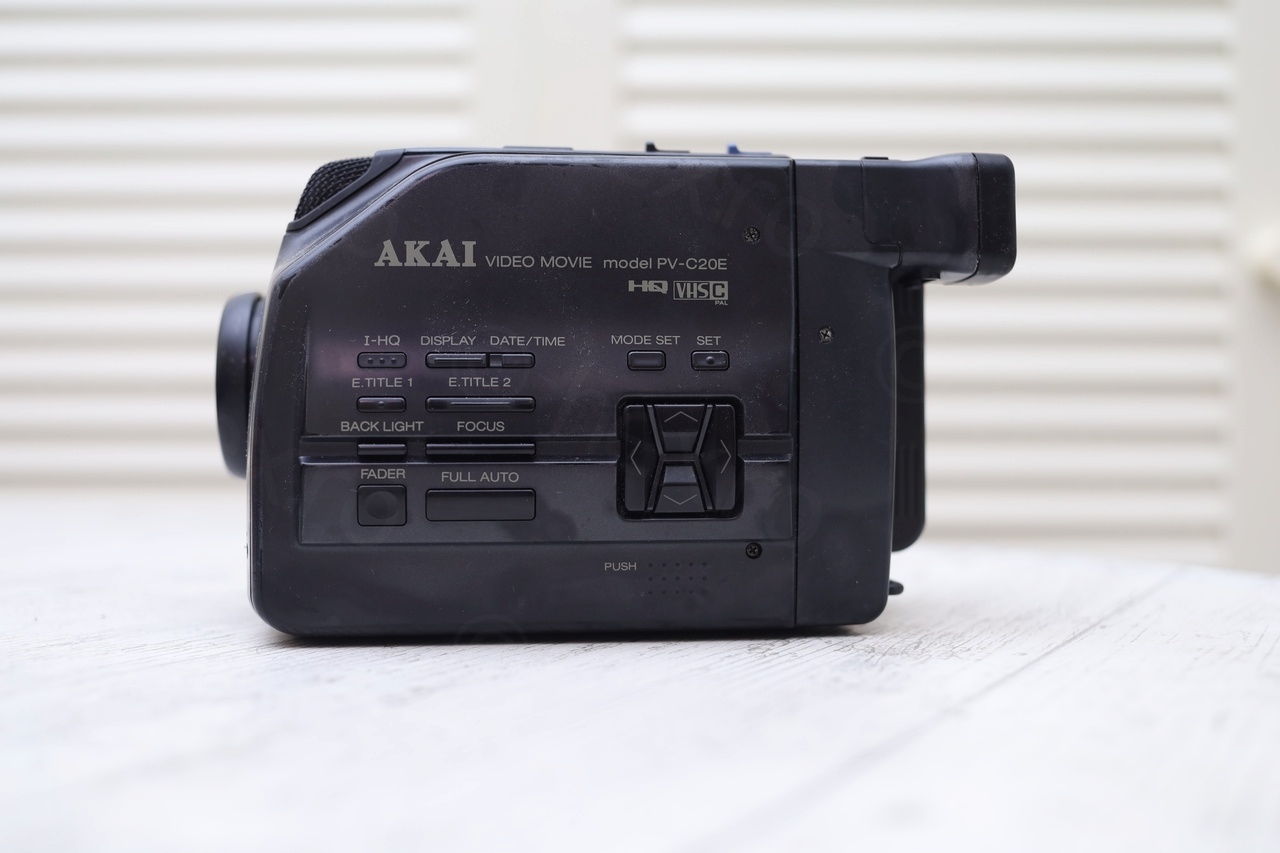
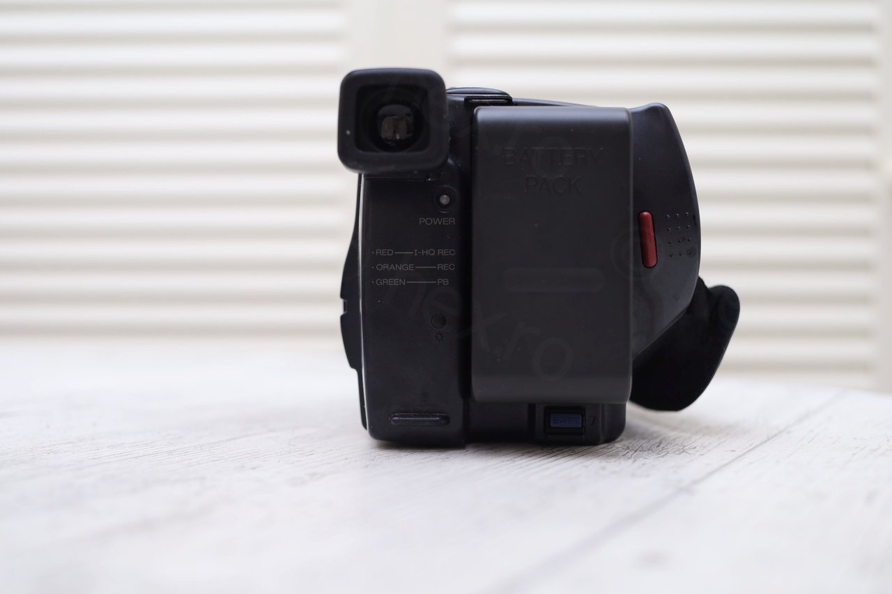

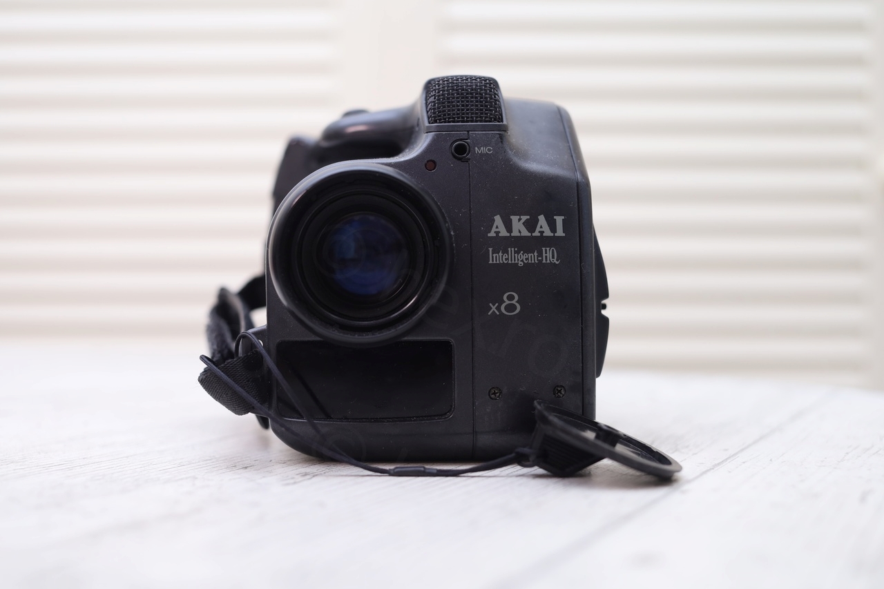

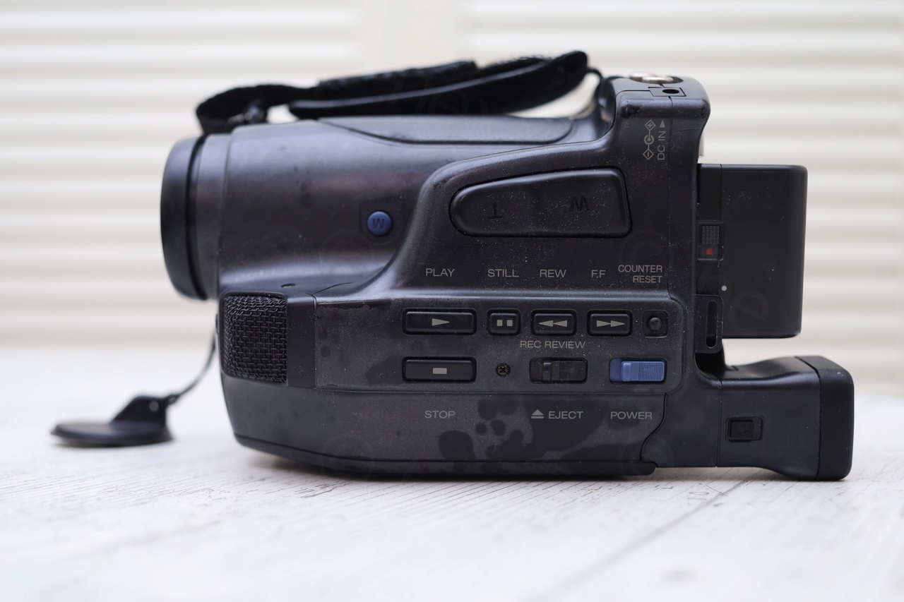
The camera looks compact, if I compare it with other CRT cameras that I find from time to time. The Electronic View Finder unit is built into it, thus not detachable.
I’ve tried power it on (since I could see the expected voltage on the battery), but except drawing 20mA and then immediately shutting down – camera did not exhibit other behavior.
Opening up the camera
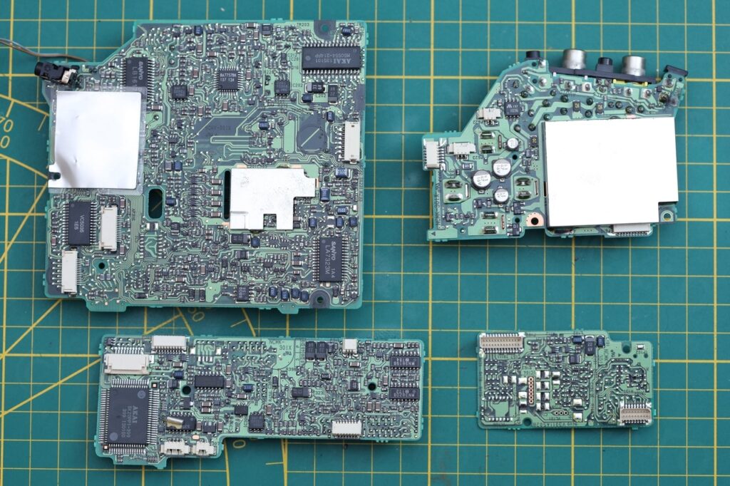
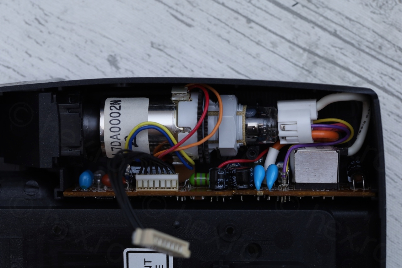
This was a very easy operation, although there are many many screws. Eventually the back just popped out – and to my surprise, it contained the EVF unit entirely, both the CRT as well as the driver board:


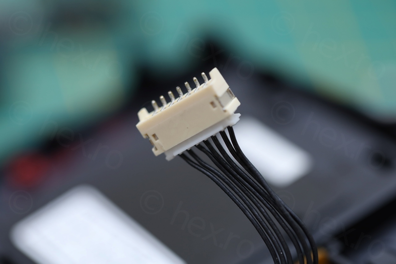
There are 7 control wires going to the EVF unit, and I was able to identify each of them – but on this a bit lower.
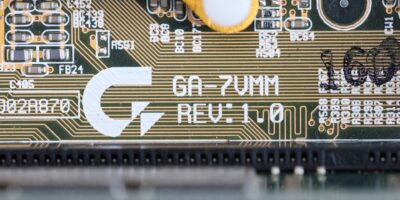
To help using tiny clamps to provide signal to the EVF unit, I needed to recuperate the connector plug from the circuit board:

While opening the camera up, it was refreshing to see that there were zero bodges on the boards. It must be modern, although I was not able to see any manufacturing date stamped on the plastics that I took apart. I did not check them all though, but on those I did, there was nothing.
Identifying the signal cables
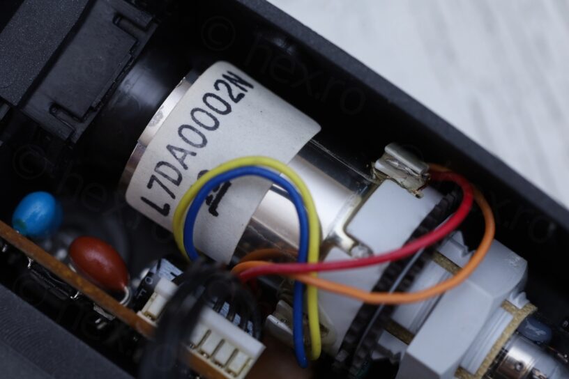
I applied the standard technique, if there is a connection from the case of the Fly Back Transformer to the connector plug, that is GND. Other PINs of the FBT that are NOT Gnd, but have continuity to the connector plug, that is VCC. Then trial and error for Video IN.

There is also an LED on the back panel, applying VCC (through a resistor, otherwise the LED is too bright) to first pin on the right (in the photo above) turns the LED to Red. Doing the same to the second pin makes LED glow Green. And both at the same time will make the LED glow Orange. I could not figure out what is the purpose of the last two pins on the left side of the image.
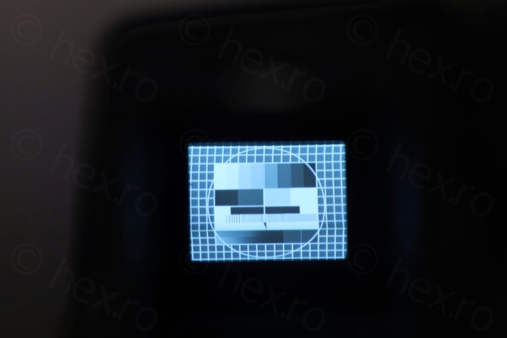
The CRT is moderately sharp without too many distortions:
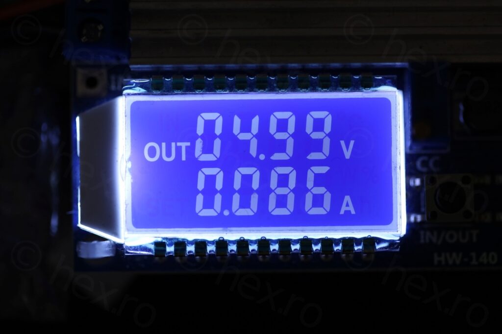
The sharpest image is when the VCC = 5V precicely (well, as precise as my cheap variable power supply, that I use for testing CRTs):
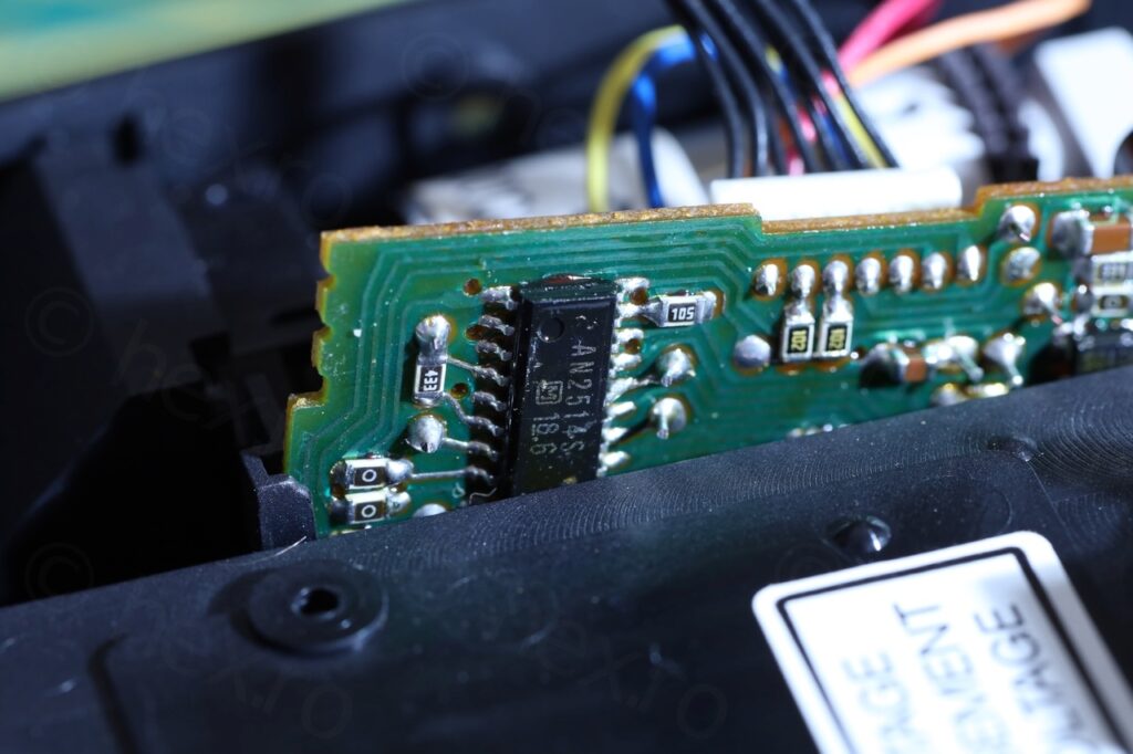
Also, the Driver IC is an AN2514S circuit, which is also not very common at least within the cameras I opened so far:
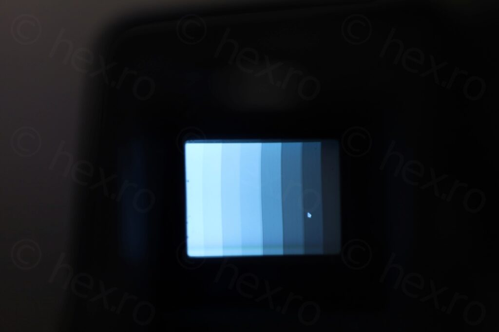
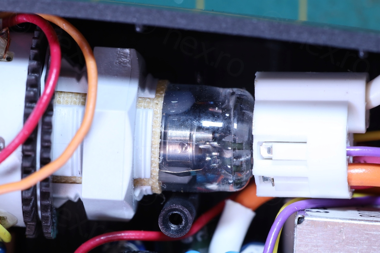
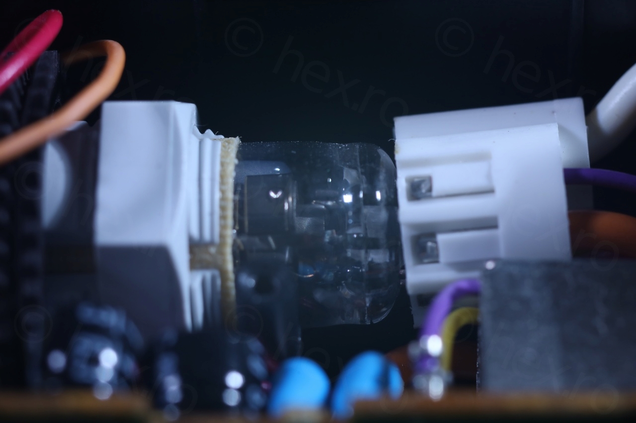
Closeups photos of the CRT

In conclusion, a CRT with a unique model number in an easy to access camera. This was a fast dismantling 🙂
Leave a Reply