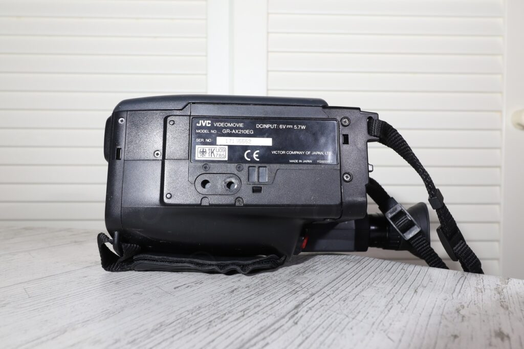
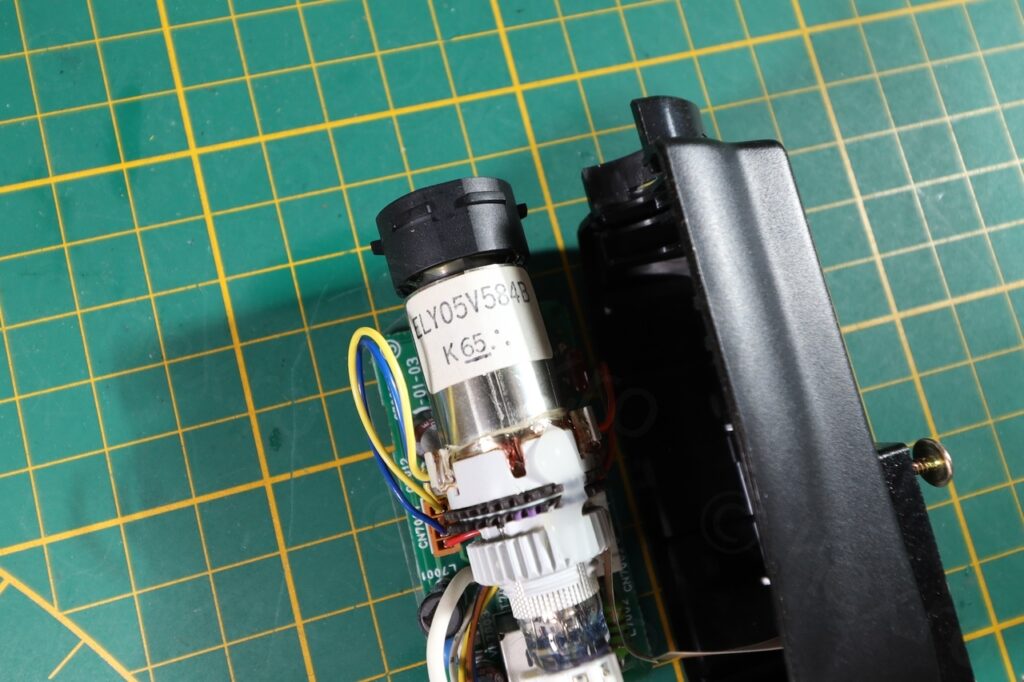
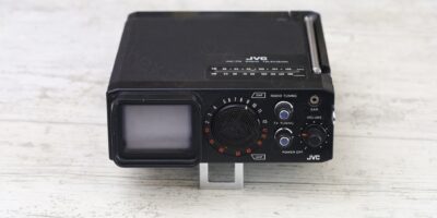
This CRT was a little surprise, I found it in a second hand JVC GR-AX210EG video camera at a flea market. The surprise was that when I bought the camera, I did not know that I already had an identical one – and as it turned out, the previous GR-AX210EG contained a Miyota 2400-58 branded CRT, but this “new” one was manufactured with an ELY05V584B !
Camera overview
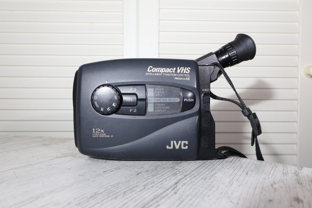
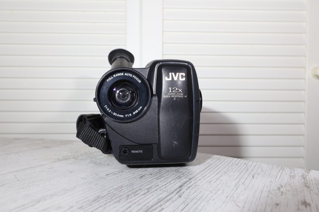

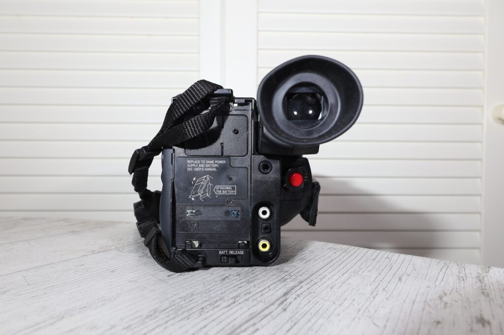
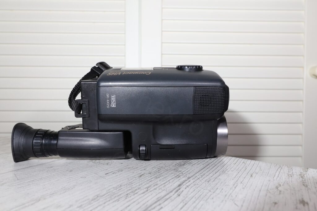
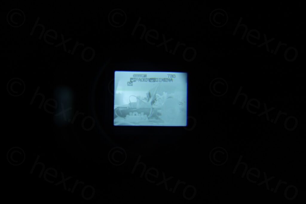
Before taking it apart, I grew in the habit of powering on the camera – just to make sure that the CRT works – at least I know what I am up against before I start. And it looked good:
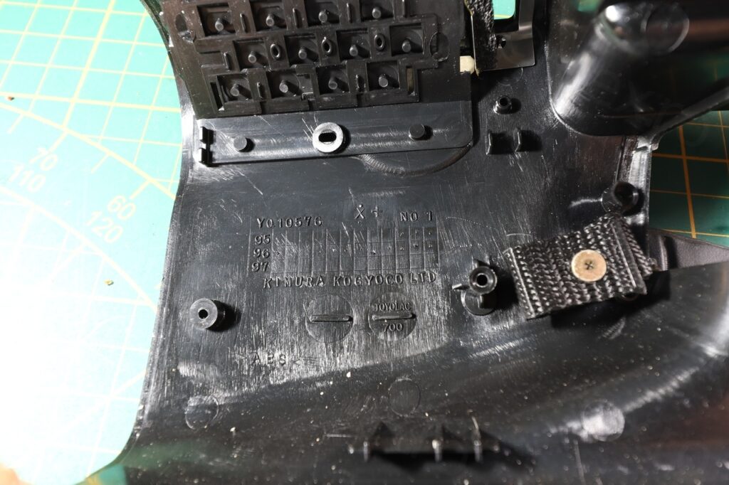
Dismantling proceeded as usual, a little tedious for these JVC cameras but no surprises:
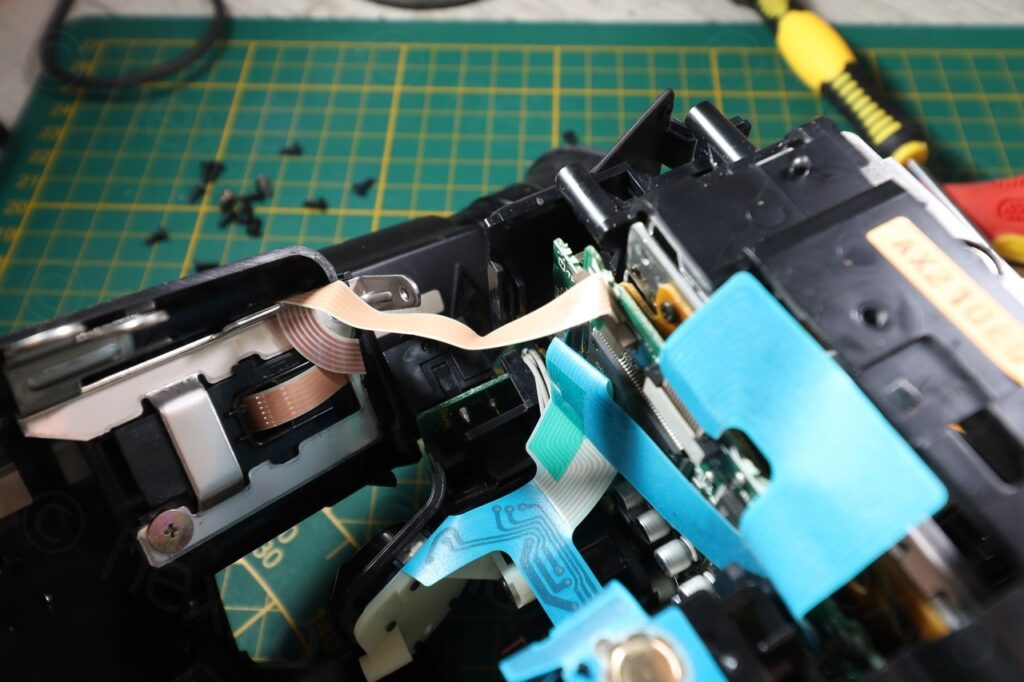
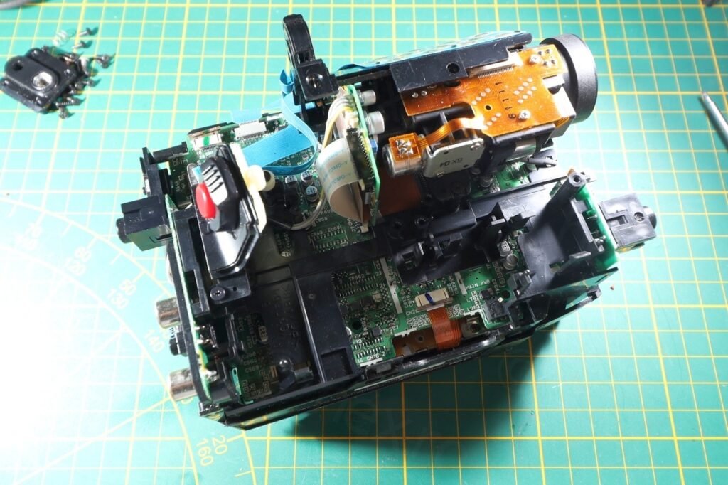
A flat cable connects the electronic viewfinder to the camera’s motherboard. To make testing easier (to send siganls to the EVF) at least one connector more needs to be de-soldered, instead of trying to fiddle with the flat cable connector itself.
EVF Unit
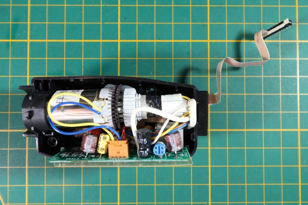
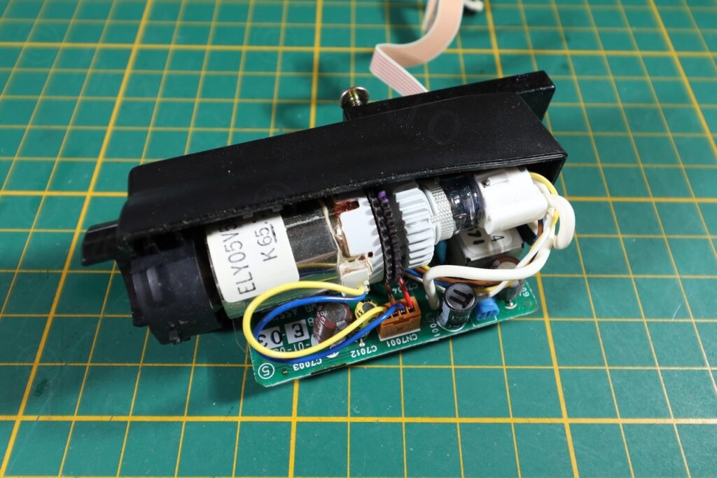
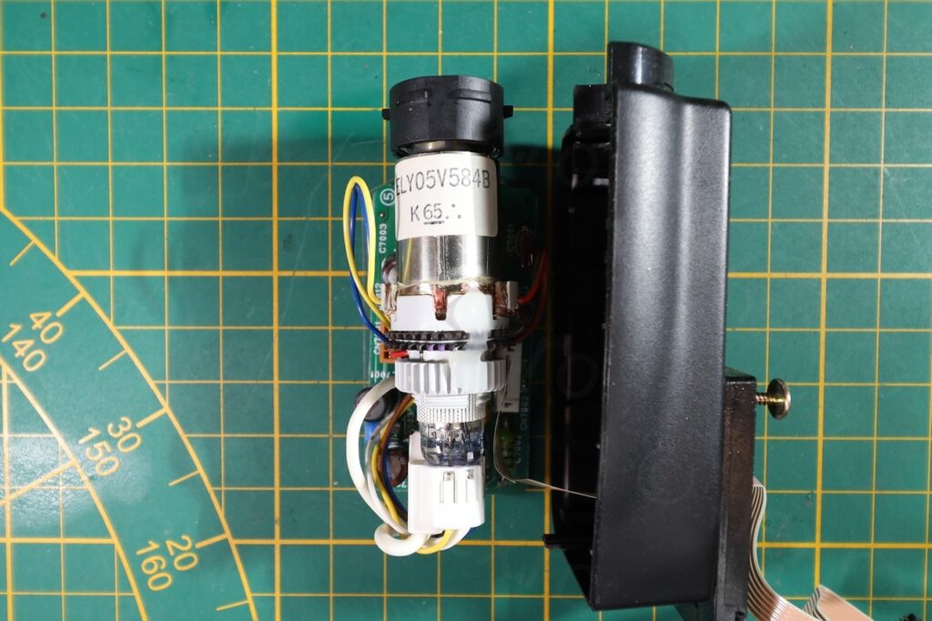
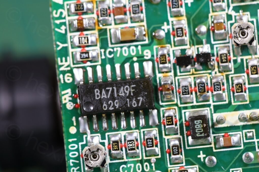
The driver board too looks different than the other GR-AX210EG camera, for example, the driver IC (BA7149F) is mounted horizontally:
Locating the signal pins is easy and I decided to order a set of smaller clamps that make attaching input signals easier.
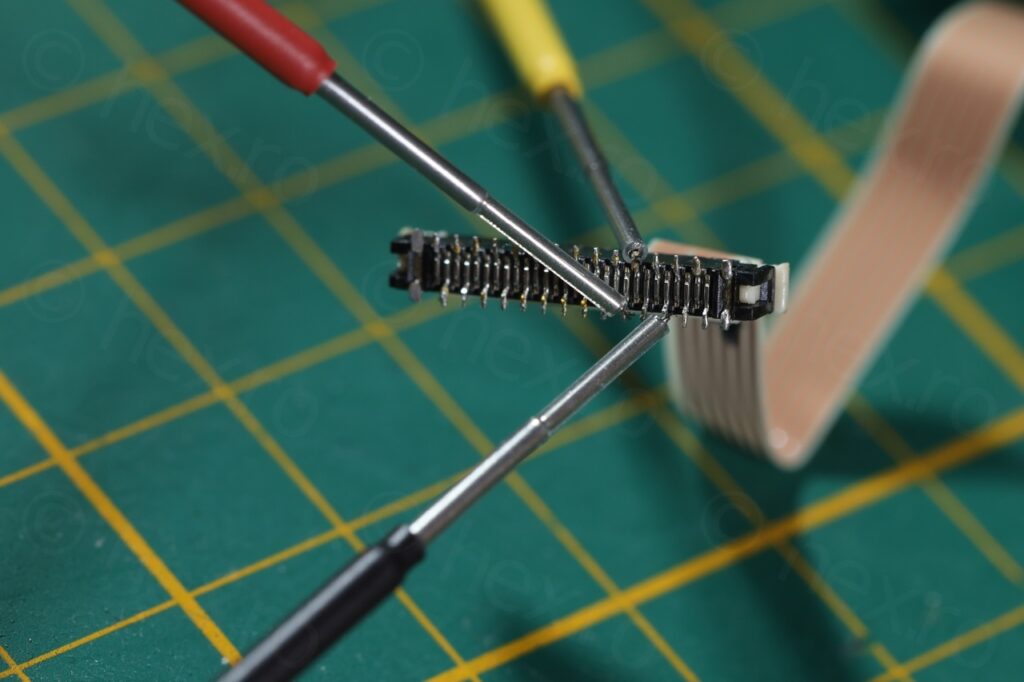
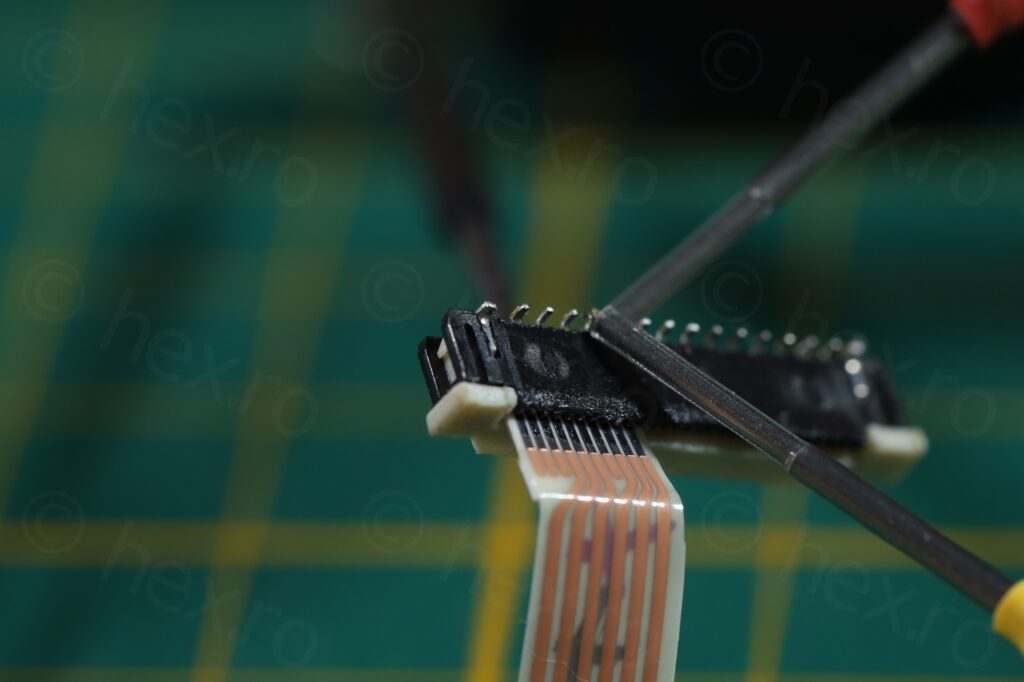
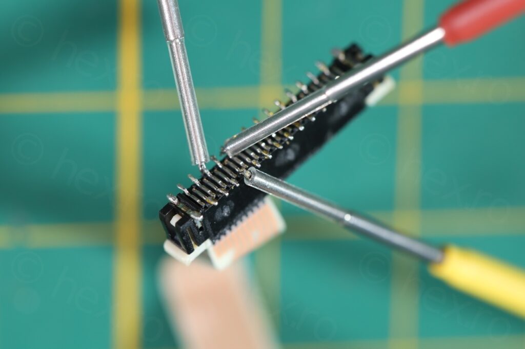
To identify the signals I used the meter in conductivity mode -> the external case of the Flyback Transformer is connected directly to GND, and some of the pins of the FBT are also connected to VCC. Sometimes, the meter beeps shortly when touching the VCC line – not always. Then, to find the Video IN is just a matter of trial and error by trying every other pin until an image appears on the little CRT.
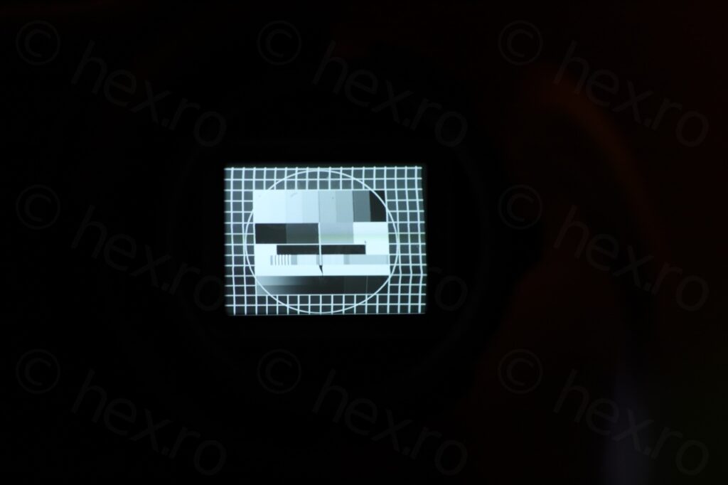
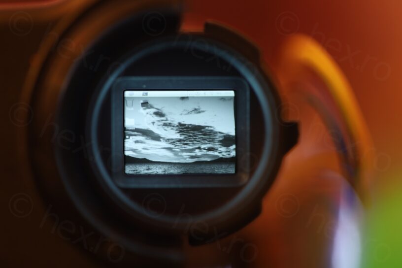
And an image did appear!
I’ve merged the two images below into the third one using GIMP:
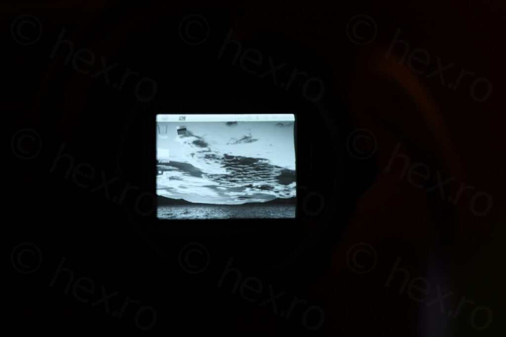
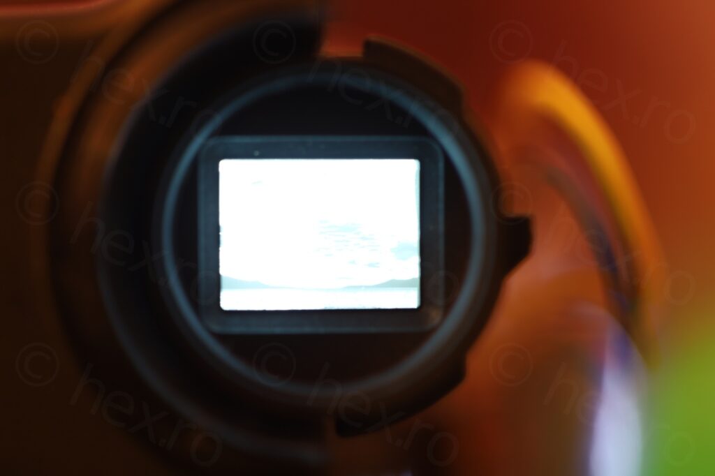

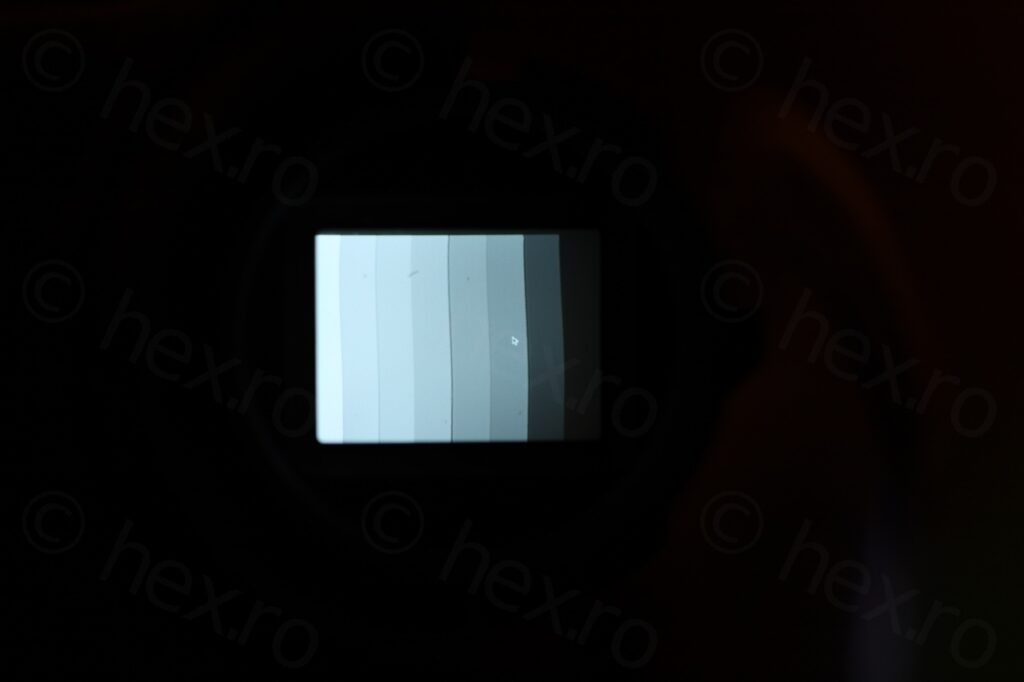
And two more test images – the CRT is looking good. The test images are taken with the Canon 100mm Macro lens, at its closest focusing distance, using a Canon RP full frame camera.
This was a little disassembly – started up boring, since I realized I already had dismantled an identical one before, but, as luck would have it, the excitement stemmed from the EVT unit that was different from the previous camera.
John
Hello friend! I admire your work and whenever I need to work on a mini crt I come here, but I’m having a lot of difficulty connecting this model, I wanted to solder the wires directly to the board but from the images I can’t identify which pin is the correct one, can you help me? Since the board has six pins, 3 on top and 3 on bottom, can you send me a photo showing which pins are negative, positive and video?
viulian
Hello,
Sorry, I cannot help 🙁 I don’t have the photo – since I almost never connect the wires to the board directly.
I suggest you follow the algorithm I use to find it. Is not perfect, but most of the time works.
The exterior of the Flyback transformer has continuity to GND. Also, most likely there is a capacitor between VCC in GND. Measuring the other non GND input pins in continuity mode you, at one moment you will find a pin where the meter beeps a bit and then it stops. That one is most likely VCC (as you are probably charging that capacitor, so meter sees a very small resistance for a little bit).
Then trial and error for the Video IN pin.
Of course, all this should be with board disconnected and discharged, otherwise you may risk some sparks.
John
perfect friend, I managed to turn it on after a lot of trying directly on the board, my struggle now is finding a mini crt miyota 2400-54 🙁 here in my country I can’t find absolutely any JVC model that comes with this model, only the models ELY05V584B are you interested in selling me some working Miyota CRT units? If so, can we close a deal?
viulian
Hey John, glad to hear you managed to get it going 🙂
Also, watch out, it was pointed in one of my blogs that ELY05V584B (for example) is not the physical CRT “bulb”, it is the deflection plate. Have a look at this blog please at the first comment: https://hex.ro/wp/blog/ely07v552a-mini-crt/
About selling, I would prefer to not sell .. Shipping is very expensive (even inside) Belgium – and I think you are better off having something from EBay.