

Introduction
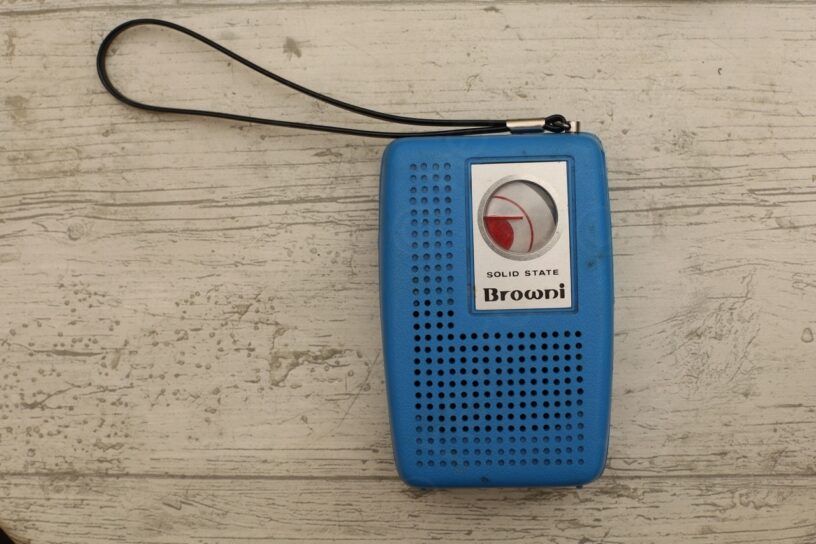
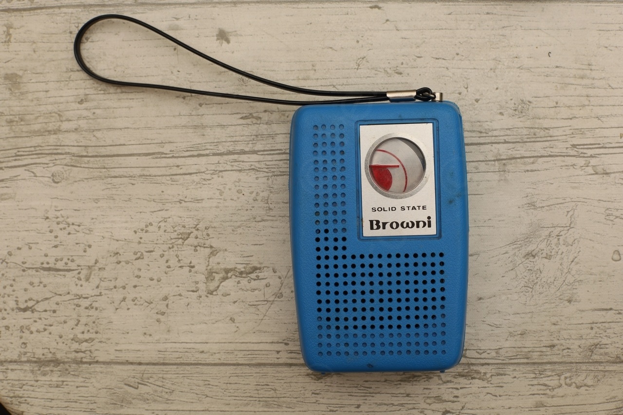
I bought this small radio for probably 1 or 2€ but I do not remember exactly; compared to other on display it looked the best, and I was able to negotiate the price as the tuning dial face was loose and rattling inside.
Visual Problems
Back home I have also discovered that the logo also came loose! Poor quality glue ?
History
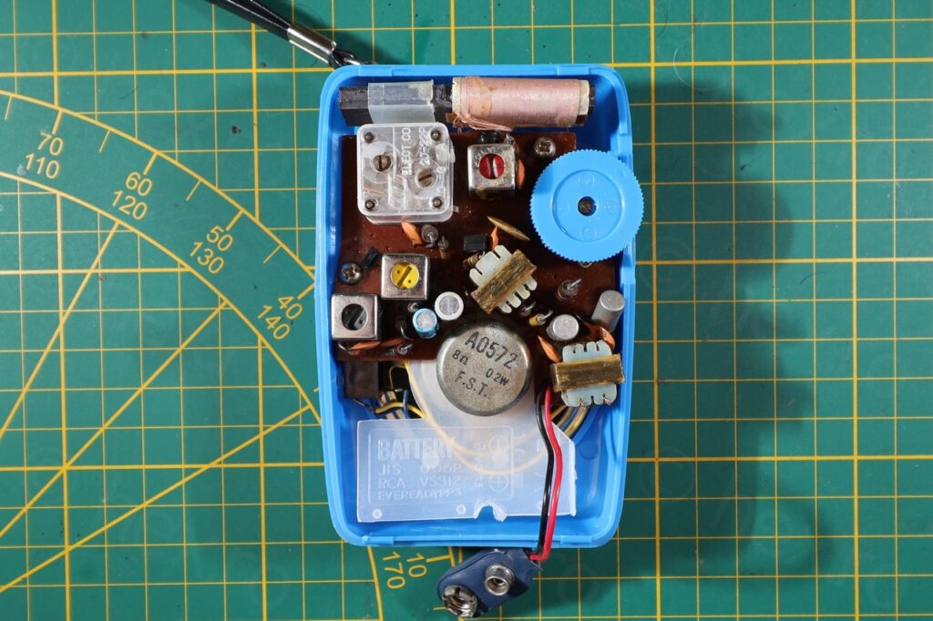
Before proceeding to the repairs, I was curious to see when the radio may have been produced – there are absolutely no markings inside and was also hoping to find a schematic in case something else needs fixing.
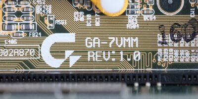
A Google search about Browni radios ends up with a link to radiomuseum.org about a Browni 7 812 model, which is identical in shape, but the board was different than on my radio. Dead end.
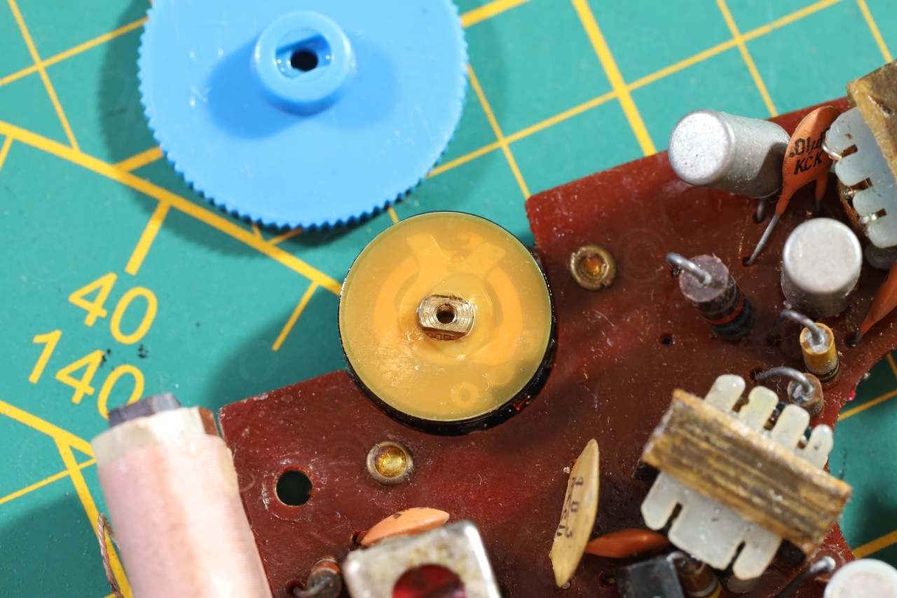
The next step was observing that one of the transistors has a dome shaped top …
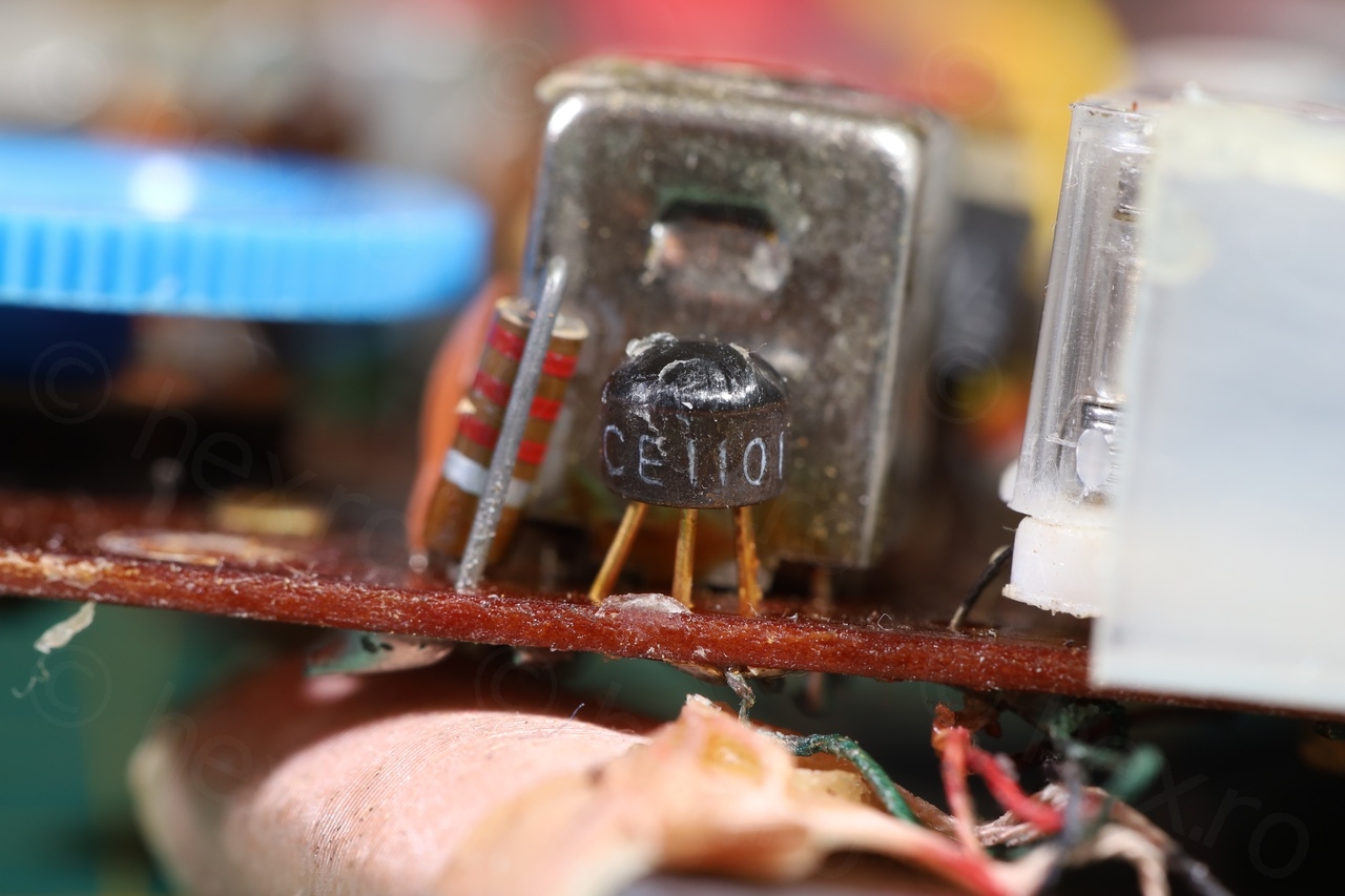
… and I remember shango066 has some repair videos on pocket radio transistors where he mentions these dome shape transistors. Hmm. A quick on his youtube channel and lo and behold:
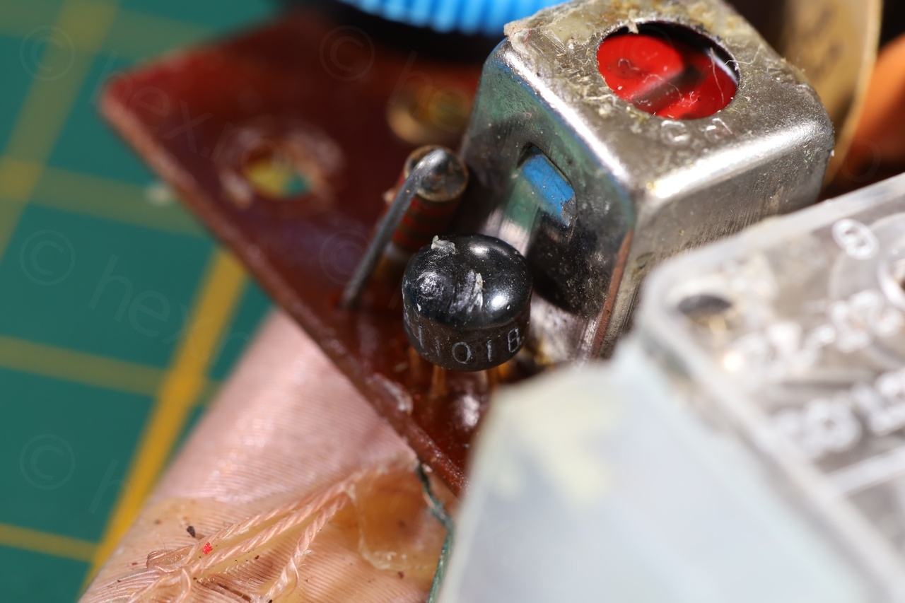
Where, surprise, surprise, the radio looks identical outside and almost identical inside …
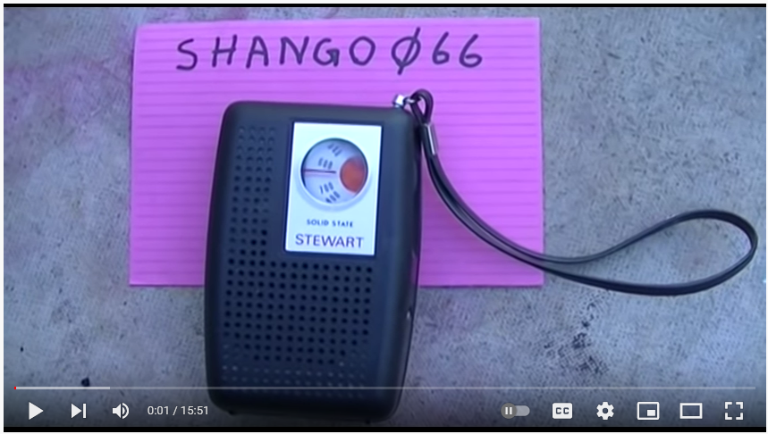
… but the radio is called Stewart!
Not only that, but Shango066 goes on saying that these types of radios were very common. Few more internet searches later, but now with Stewart Radio criteria, and I start realizing shango066 is right – for example:
In conclusion, am I the owner of a small radio of a very tangible but diluted history!
Visual defects repair
Dial face
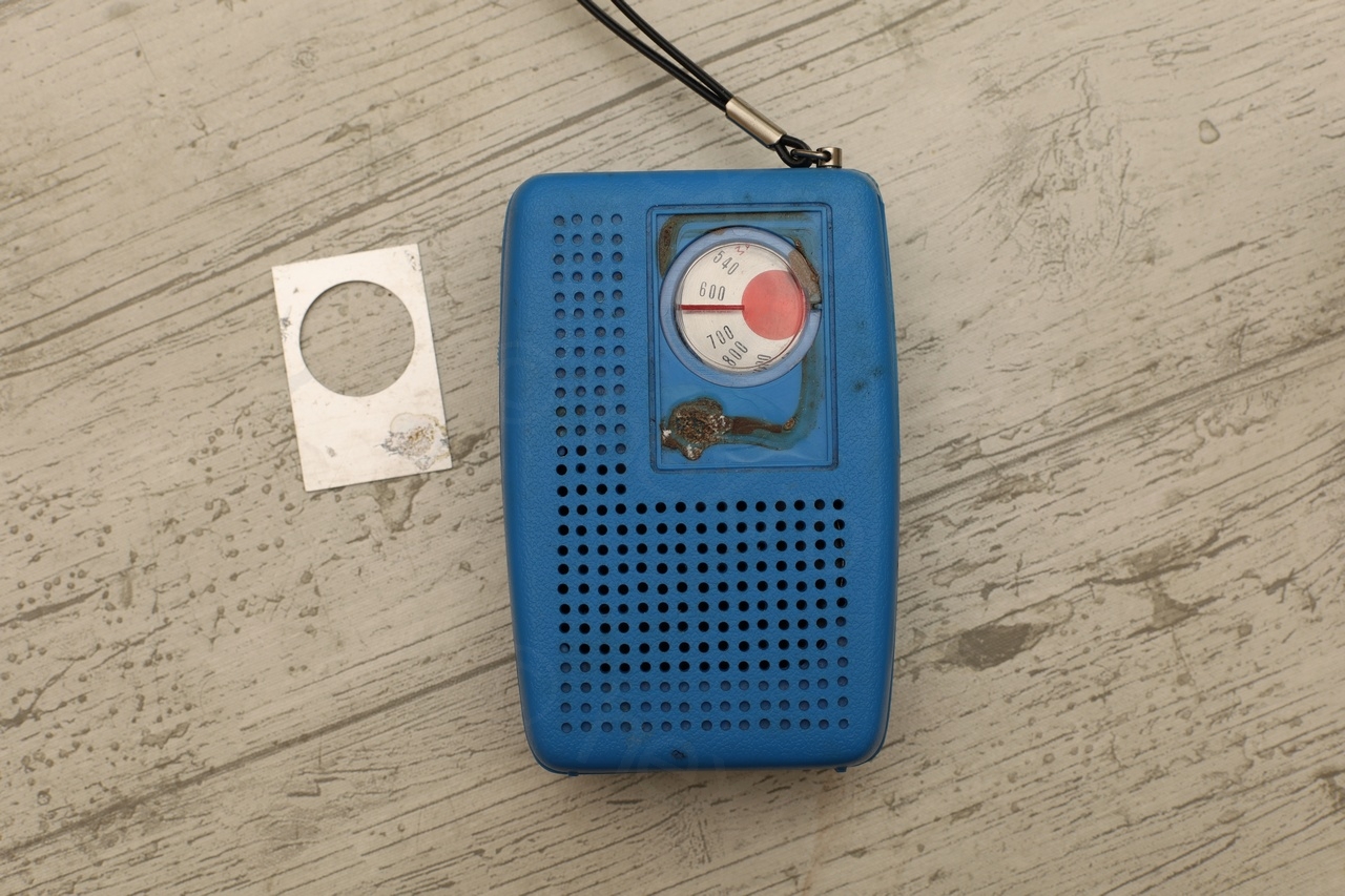
The radio works but I wanted its visual defects fixed, most pressing one being the dial face.
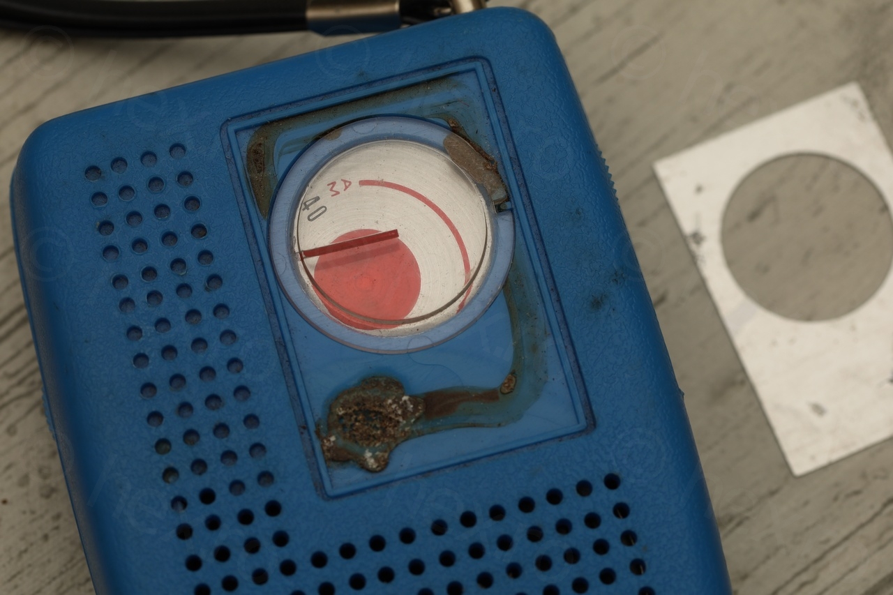
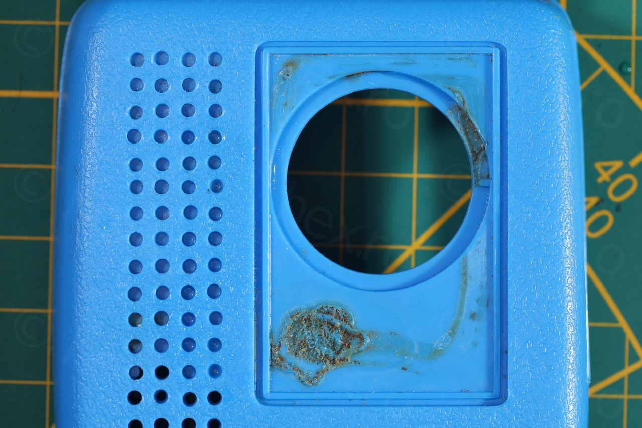
In the video of the Steward Radio, shango066 has issues taking the dial face off (it was glued on very strongly) but surprisingly, on this Browni Radio, the glue came loose leaving a brown crust behind:
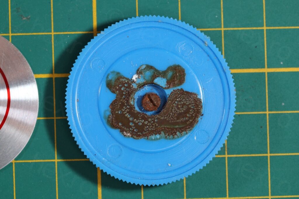
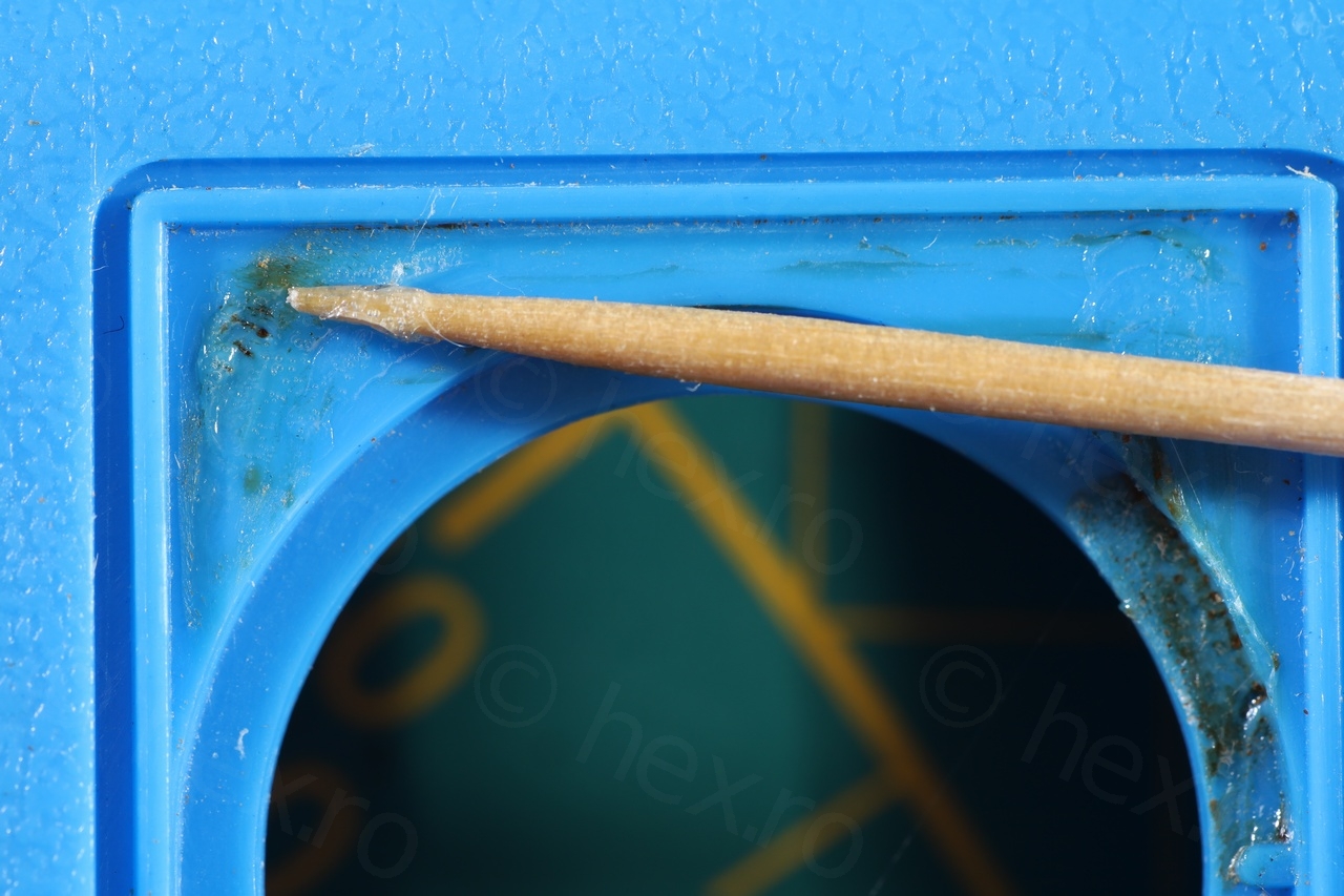
I have tried Isopropyl Alcohol as well as Glue Gone product, but it would not melt. However, it soften up enough that I could scratch it away with the finger nail. Thus, I decided to use a wooden tooth pick scrape it away as much as I could.
One dilemma was how to glue it back without loosing access to the center screw in case I need to service it in the future ? After considering few types of adhesive, I have decided to go for a thin double sided thin tape to reattach the dial face:
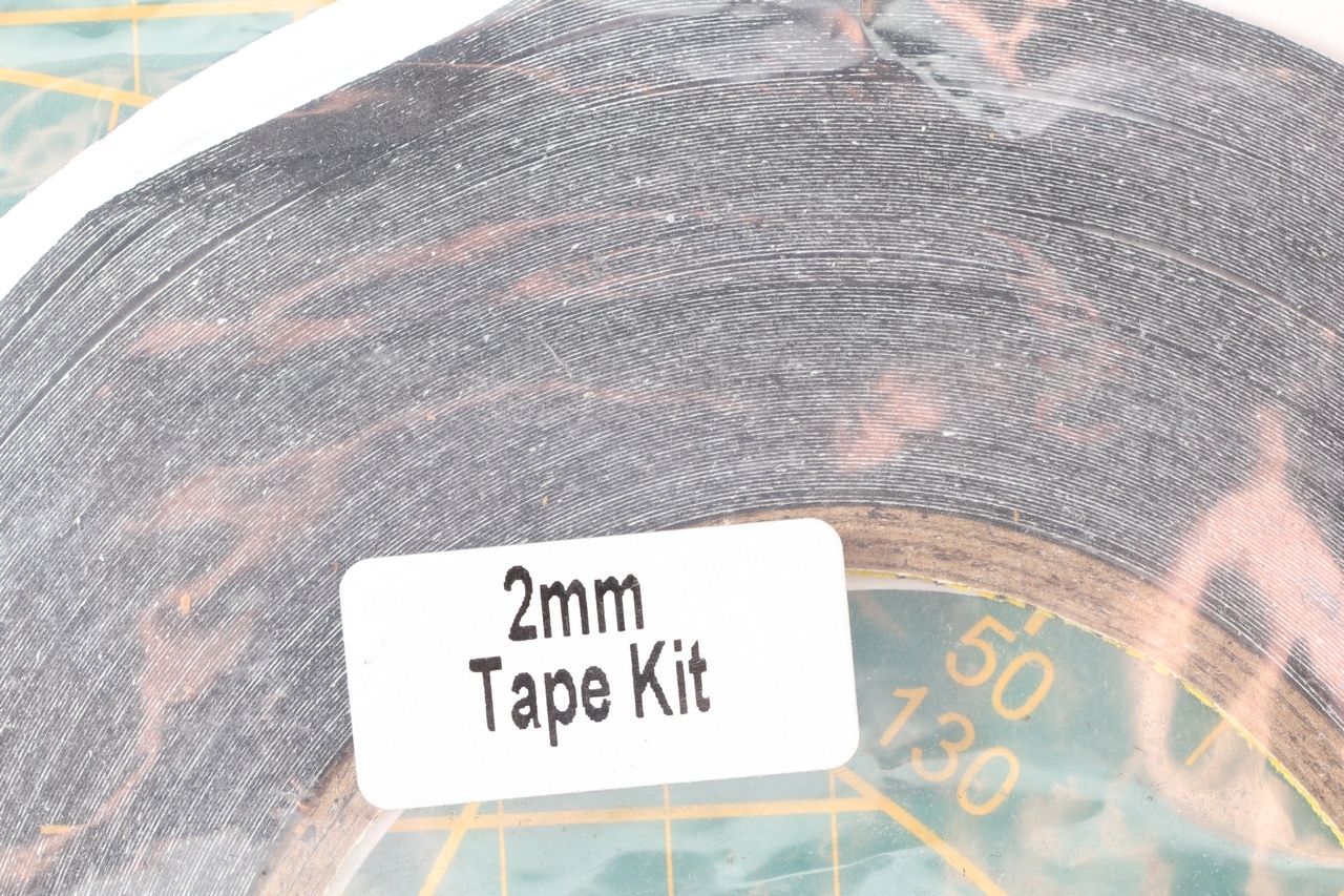
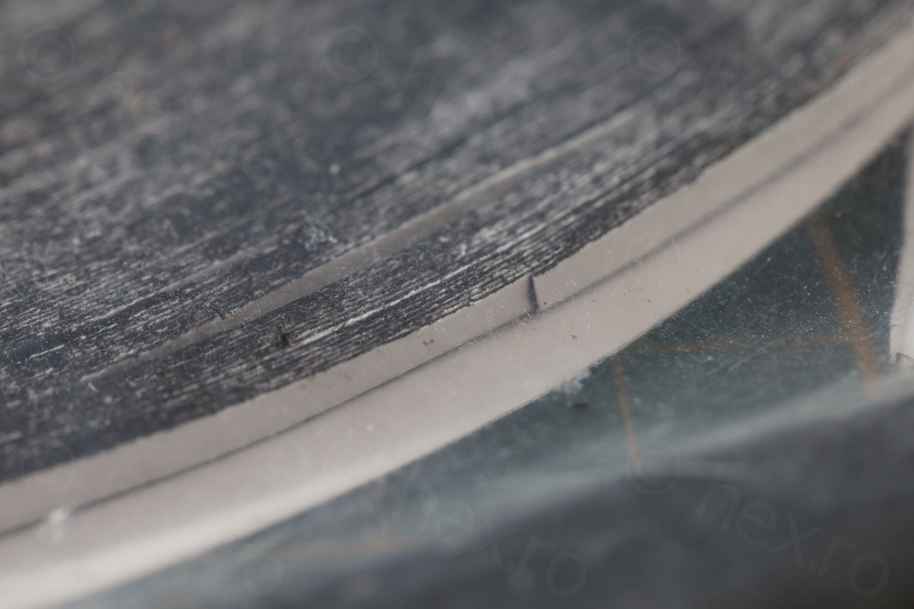
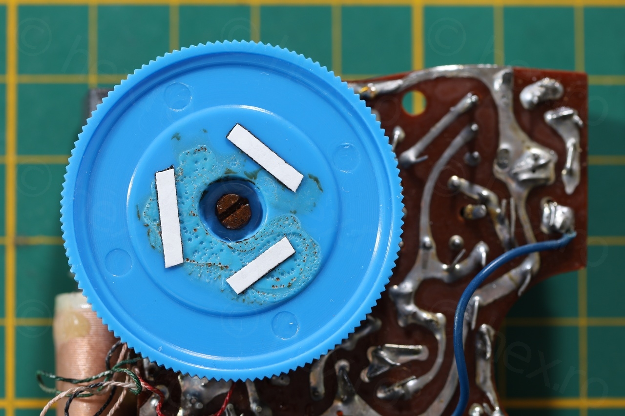
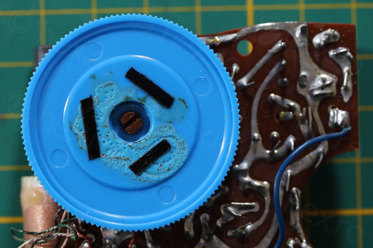
The tape is thin enough that the dial face stays sunken inside the plastic case, but it is flexible enough that I could rock the dial face left / right until the tape gives up, allowing access to the screw inside.
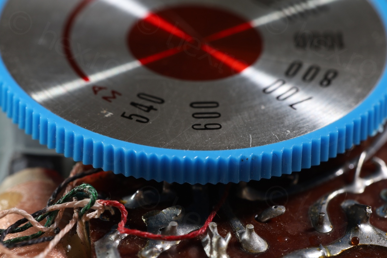
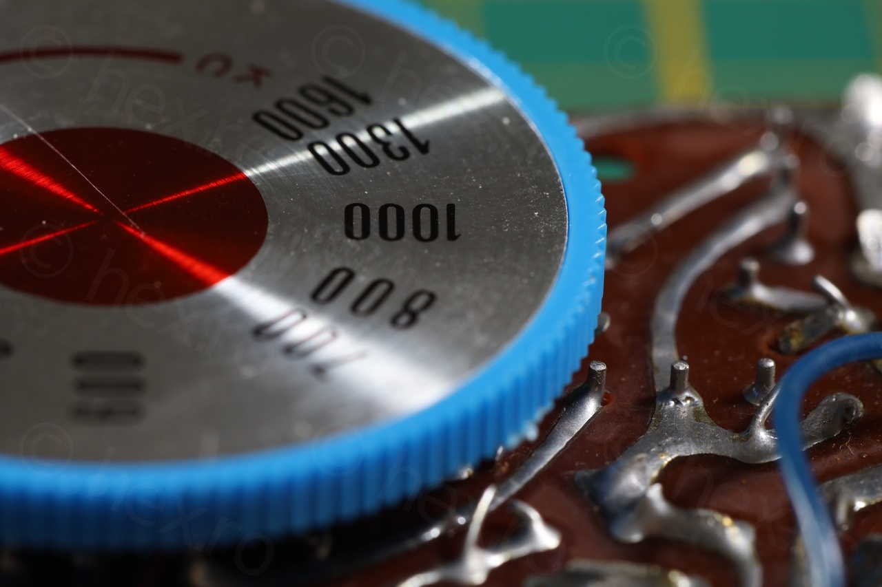
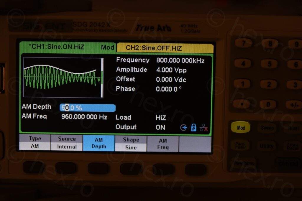
Another tricky part was determine on how to center the dial face so that the frequency is aligned with the red indicator. The dial face has no notch or anything to help with the alignment. I figured I can use a Siglent 2042X Function Generator to generate a weak AM signal on 800KHz and try to center it there:
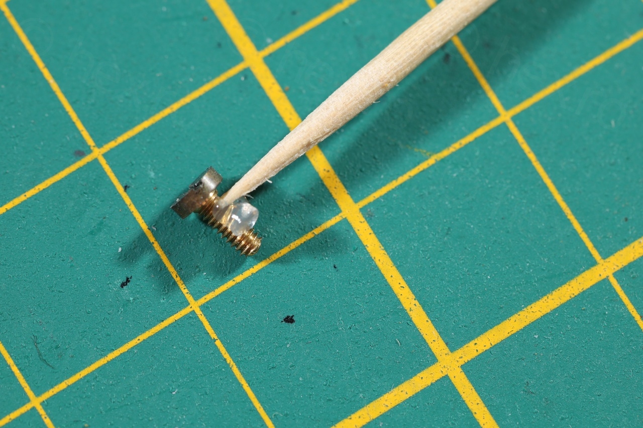
One remaining issue was the screw that was rusted. I tried to clean the rust a bit but I like the screw rusty as it was – it does speak about the age of the radio so why not ? However, a little silicone grease would do no harm, both on the shaft as well as on the top, to try and keep moisture away.
Logo
To reattach the logo I decided to go for a more permanent glue, Pattex Contact. The Logo (and the transparent plastic cover) do not block access when servicing the radio. Of course, I have also cleaned the old glue as much as I could. Used a toothpick to apply small amounts of Pattex Contact to prevent it from trying to escape from the sides when pushing down on the metal sheet:
Crackling volume pot
The volume pot was not in a good shape, turning it would create cuts or pops and a audible scratchy sound. I took off the dial, applied some contact cleaner, positioned the dial back. In the process, I have also greased the screw that kept the dial affixed to the volume pot:
Loudspeaker
I find it funny to call these small speakers ‘loudspeaker’, they can be loud, is true, but still ..
The speaker was supposed to be attached with two dabs of brown glue and kept pressed down by the headphone jack. However, the construction is very poor and the jack not only presses down, but lands on the angled part of the speaker thus also pushing it away:


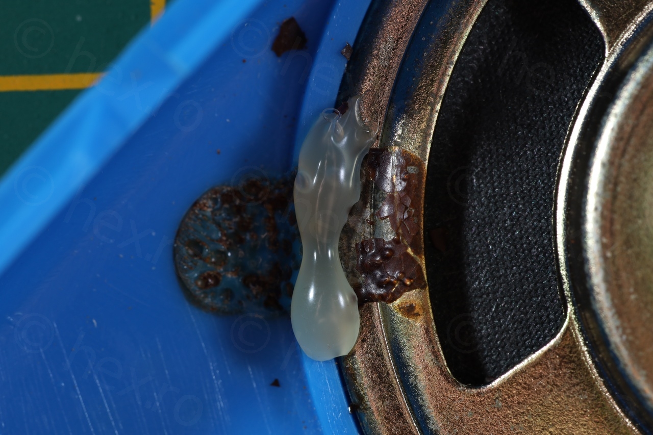
I decided not to tighten the headphone jack so strongly (to reduce the side force) and to use hot-glue to keep the speaker in place – again, should I need to service it, hot-glue would be easier to remove. I have also re-centered the loudspeaker inside its groove before applying the glue:
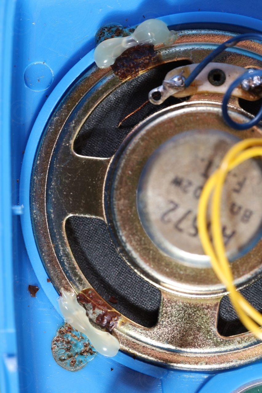
Result before reassembly:
Voltages
Since I was not able to find a schematic for this radio, the least I could to to help future servicing was the list of normal DC voltages on various traces. At least, if one of the transistors will go bad, or one of the capacitors (which I have not replaced since they do measure acceptably), at least I will have a reference with the voltages from when the radio used to run:
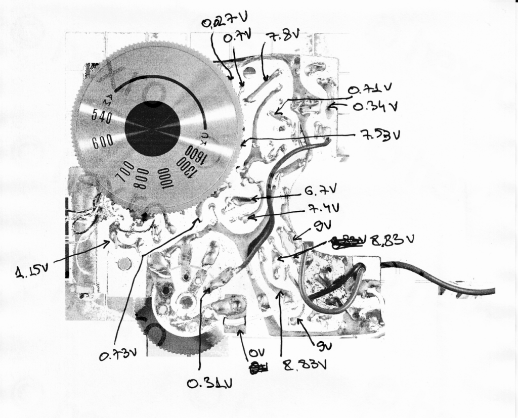
The device was powered with 9V from a power supply and turned on with the volume pot towards the minimum. Some of the traces have tens of milivolts and are not stable – I have not included those.
Video
Finally, this is how the radio tunes. It is very fiddly and has a hiss-y reception thus the video is set load as muted – please un-mute before clicking Play.
Tuning the Browni Radio
Now the radio is ready for storage – of course, without any battery installed.
Leave a Reply