


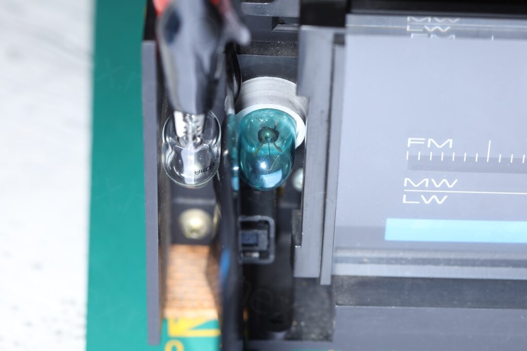
While working on the Pioneer TX-520L, I noticed the blue coating on the pilot light bulb used for illuminating the scale:
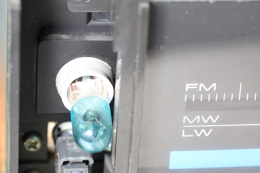
The immediate thought was that it was an attempt to try to make the emitted light appear ‘white’-er than the yellow-ish default one.
But by how much ?!
How can I quantify how much blue was added ? Luckily the bulb was working, but in case it burns out, how much blue should be added to match the original color ?
Consumption
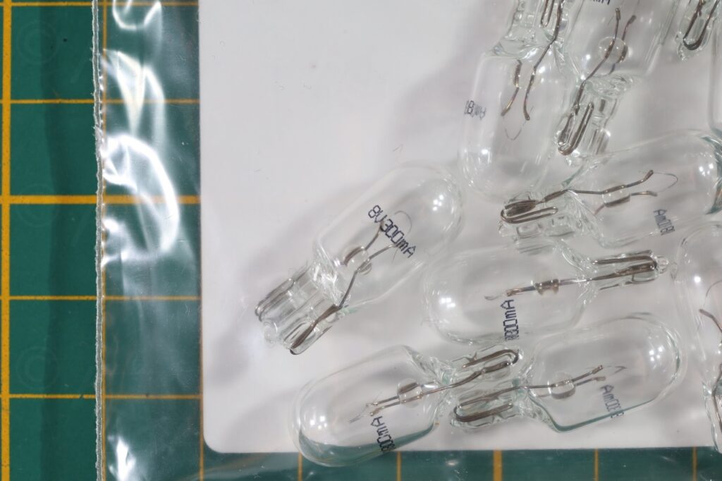
The bulb was rated at 8V, 300mA. Cross checking revealed that indeed the bulb is powered by AC current and the intensity RMS value is 0.272mA which is close enough to the rating.
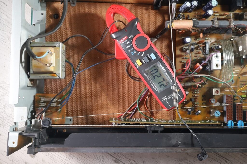
The RMS Voltage was ~8.3V, a little higher but it made sense, the bulb is supposed to be in parallel with another bulb at 8V@100mA (the dial pointer indicator light), but that one was burned out.
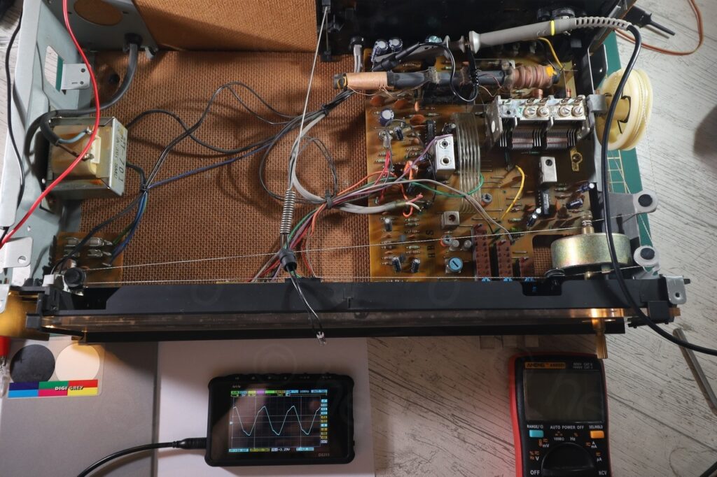
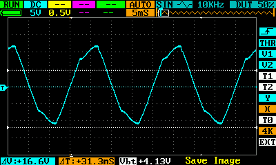
Had a look at the real wave form that was feeding it:
I decided to buy some spare light bulbs (transparent) and compare a new one with the old coated one.
Measurement strategy
Without a colorimeter, the next best thing was to use a digital camera, take two pics and compare the amount of Red / Green / Blue produced by each bulb.
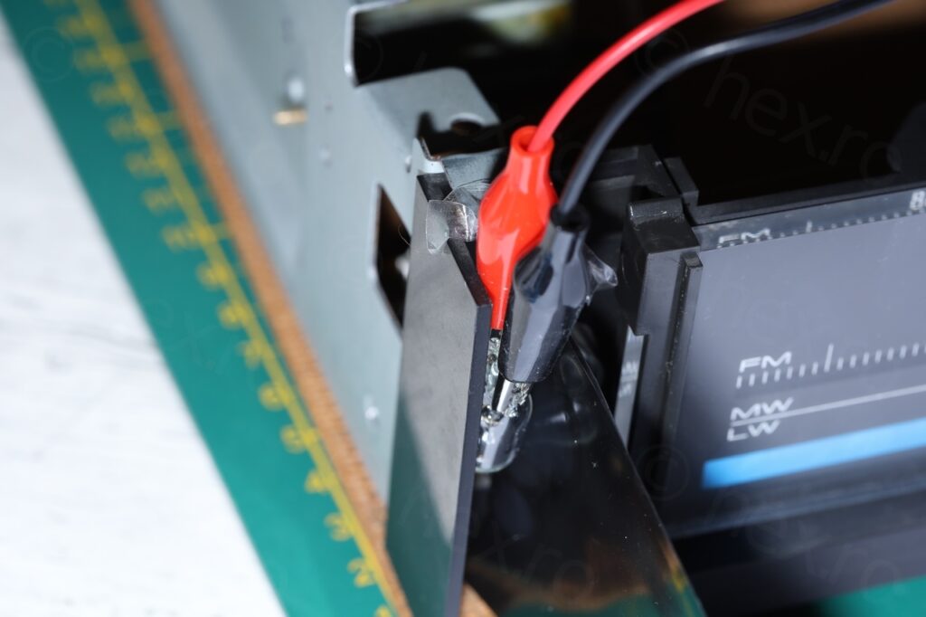
Camera should not be allowed to ‘auto’ anything – fixed White Balance (Sunny for example), same lens, on a tripod and same settings (Shutter Speed / F Stop / ISO). Take one photo, swap the bulbs, take another photo and compare.
Removing the old light bulb I would consider invasive, as the goal was to maintain the device as close as possible to stock, and starting to mess with the wiring, soldering, etc, I would prefer not to.
After seeing a reflection of the bulb in a random photo I took of the device, an idea started to form. What if I put the two bulbs in parallel and try to take a single photo ?! Few more iterations later, the idea took shape. There should be an opaque separator between the bulbs and the photo should be of the light that the bulbs shine on a piece of paper:
Another drawback was the load the parallel light bulb was putting on the transformer. RMS Voltage of the blue bulb dropped to 7.3V and intensity towards 260mA. However, this is not very far off from the recommended power draw (and light intensity), but at least now there was something to compare!
Decided to work with this photo:

Light color comparison
As a comparison tool, I used the RGB Histogram in GIMP, after selecting two small pieces from what is supposed to be the white circle.
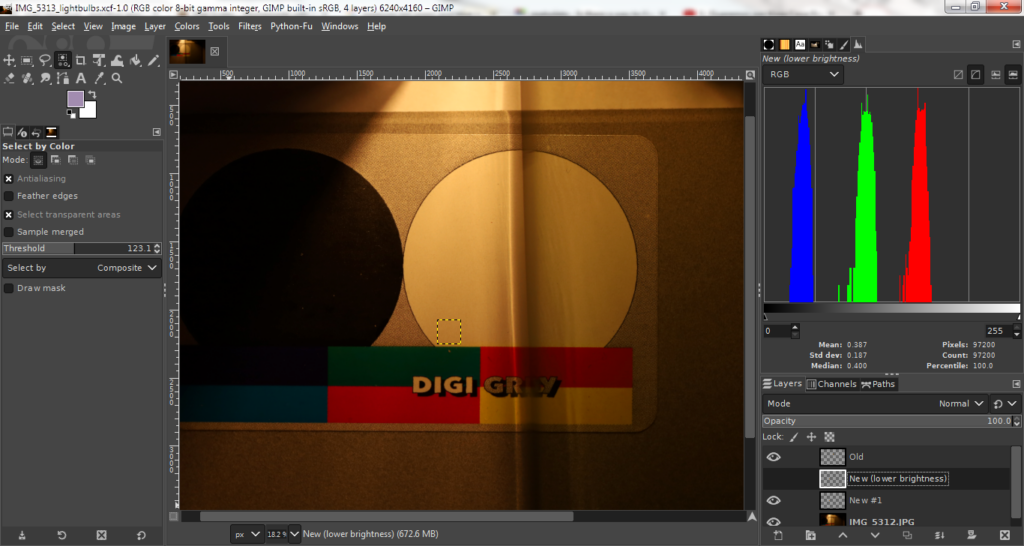
The area on the right is lit by the blue bulb, the area on the left is lit by the new transparent bulb. What is immediately obvious is that at the same voltage, the new light bulb produces more light.
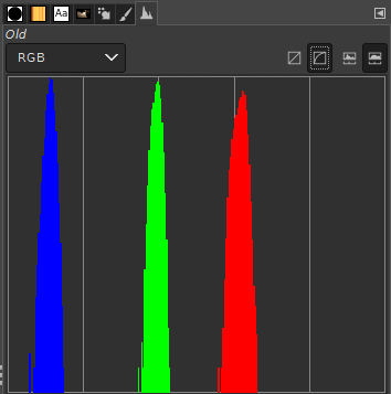
Important thing to mention, Brightness affects all colors equally, while Exposure is not. Thus, Brightness has to be used.
Conclusion
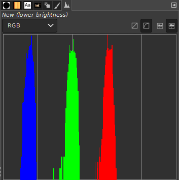
New transparent bulb is more efficient and already produces Blue very similarly to the old blue coated bulb. This is good, as it means in case the blue coated bulb burns out, a transparent new one can be used instead.
There is still a drawback, the bulb produces a bit more light that the stock. I had to reduce the brightness (form a scale of -127 to 127) with 35 to get the Red / Green to align with the old bulb; the newer bulb will need the brightness reduced somehow to produce similar light intensity. The problem is with how much ? There is a logarithmic dependency between perceived brightness and currently I have too many unknowns to continue with the calculations.
Leave a Reply