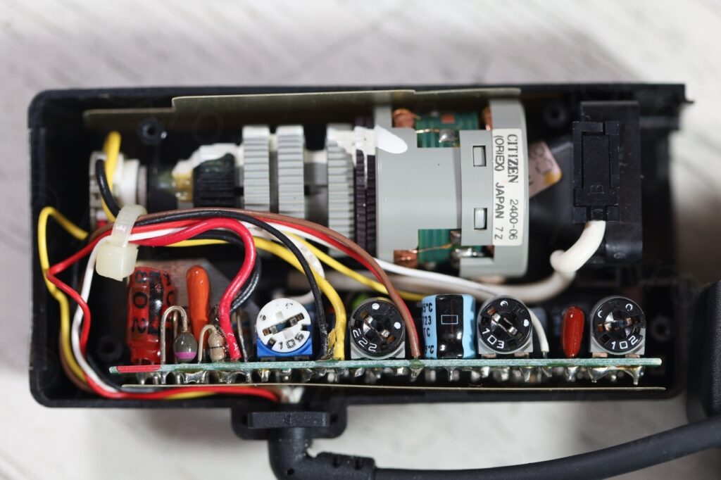
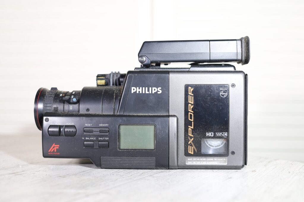
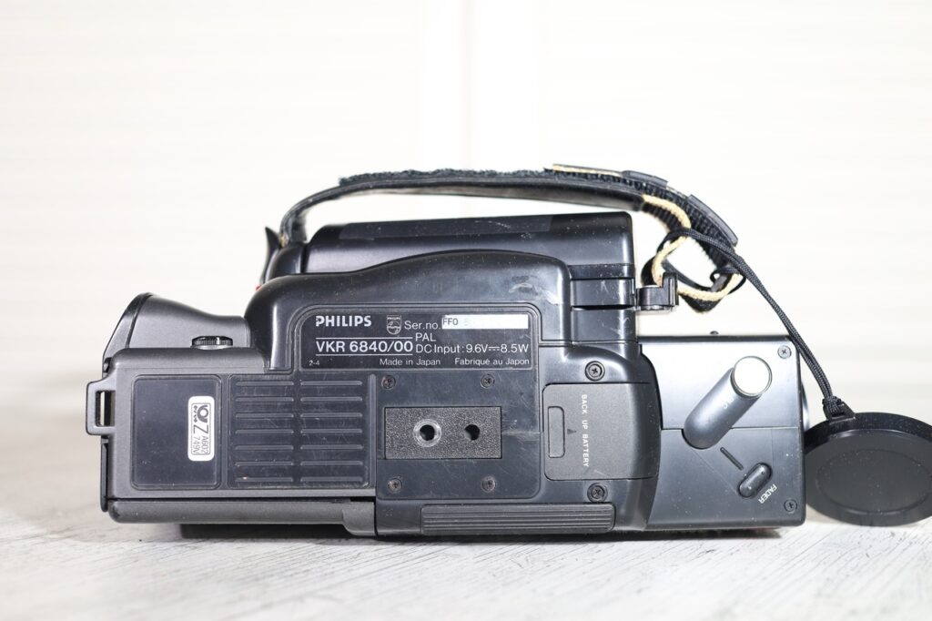
I found this Citizen 2400-06 in a Philips VKR 6840/00 camcorder camera that I got a flea market.
Camera
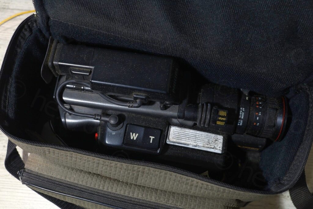
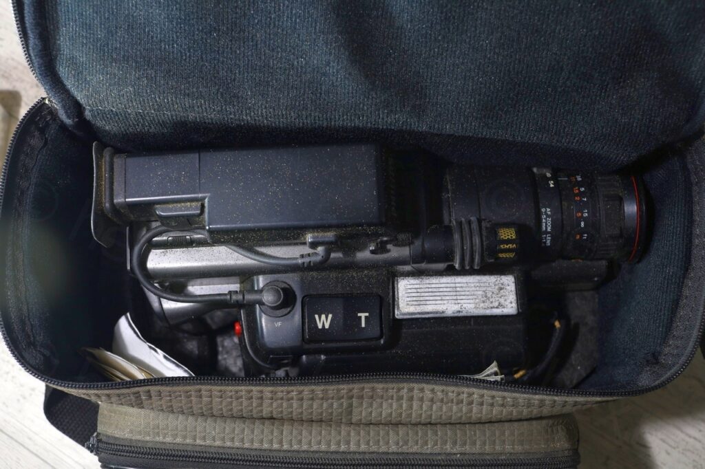
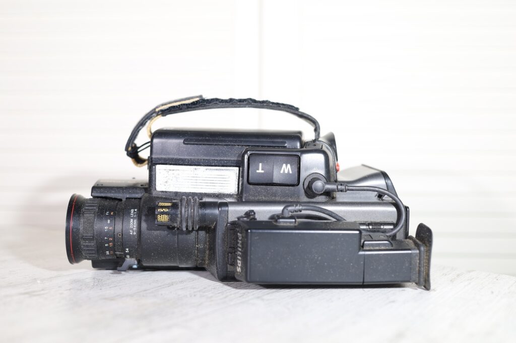
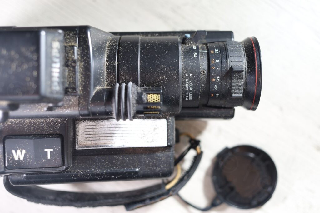
The camera was sold with the camera bag, but it was still full of dust:
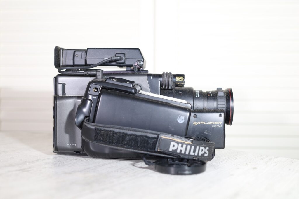
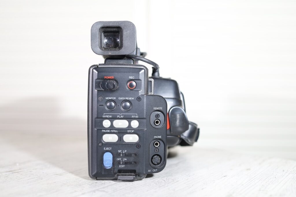
I took some pics of the camera and of the EVF unit before de-dusting:
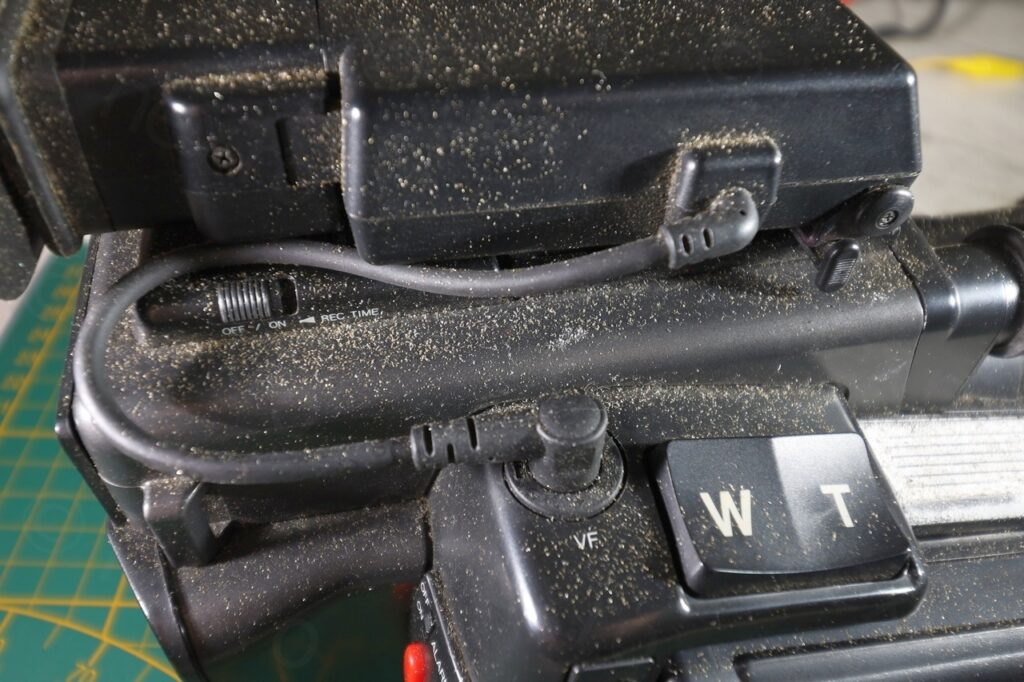
Closeups:
The good news was that the EVF unit had a separate cable connection to the camera body, usually it simplifies identifying the signal pins (power and Video In). There was also a battery attached to the camera – I never try to charge these batteries, they go directly to the recycle center:
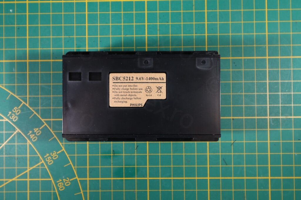
While I did try to power on the camera using an external power supply, there was no life from the camera – and thus, I could not eject the tape that was inside. Taking it apart would require more work than it should …
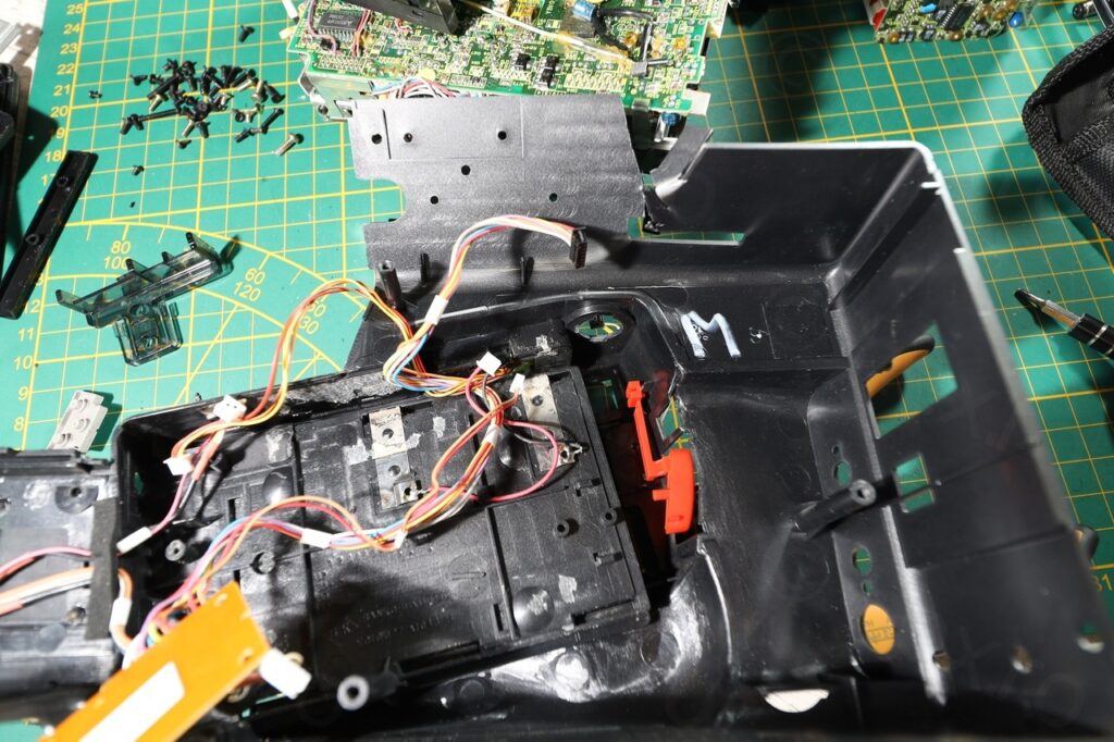
I have de-dusted the camera and proceeded with disassembly, main goal was getting the Electronic View Finder plug out – this makes it easier to identify / connect input signals. It also preserves the EVF unit as I don’t have to solder any wires on the driver board – nor cut the connecting wire and the plugs.
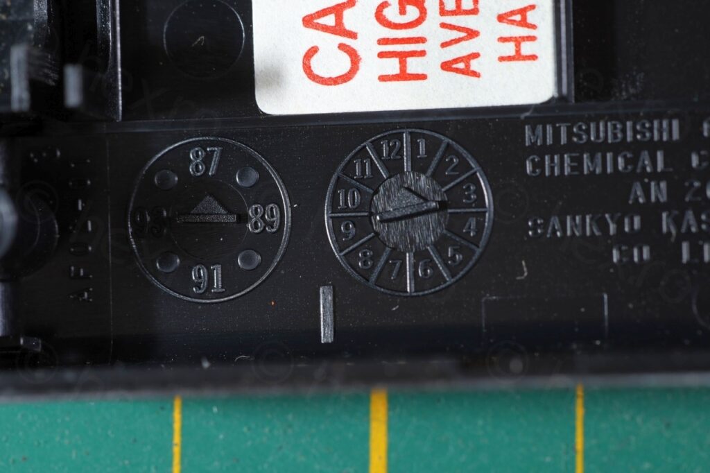
The inside of the plastic case indicates (end of) 1987 as production year; this was the easiest thing to get out of this camera though 🙂
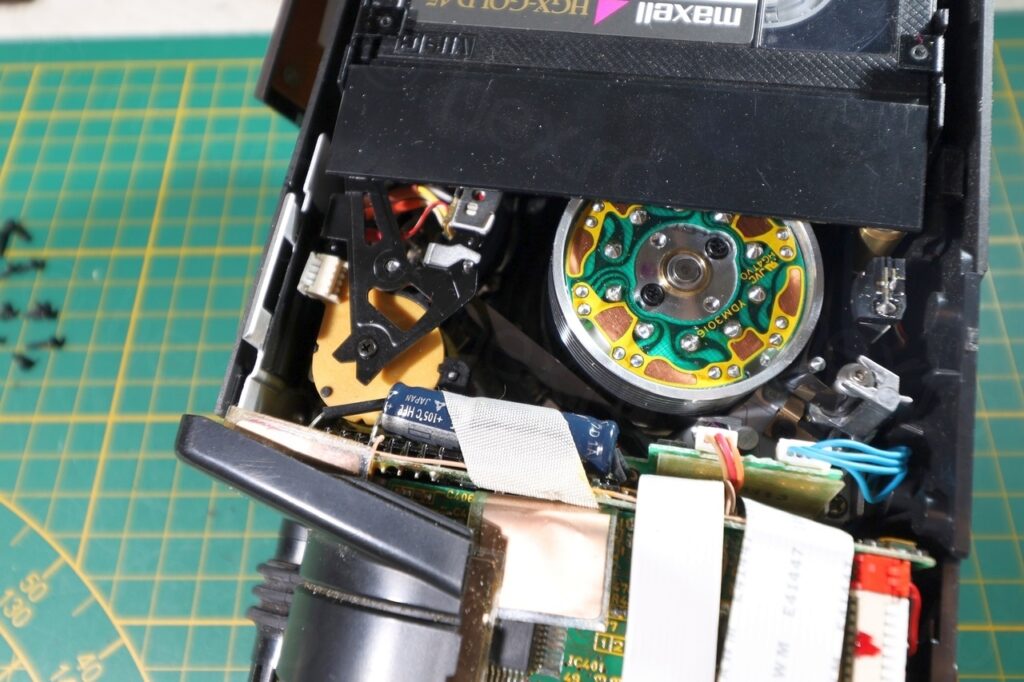
Next problem was that the magnetic tape was still spooled around the mechanism and no easy way for me to free it up (second photo above). The only way to get it out was to break aluminum stand-offs and bend away the metal holding the casette inside. Very delicate operation, but I was able to salvage the tape.
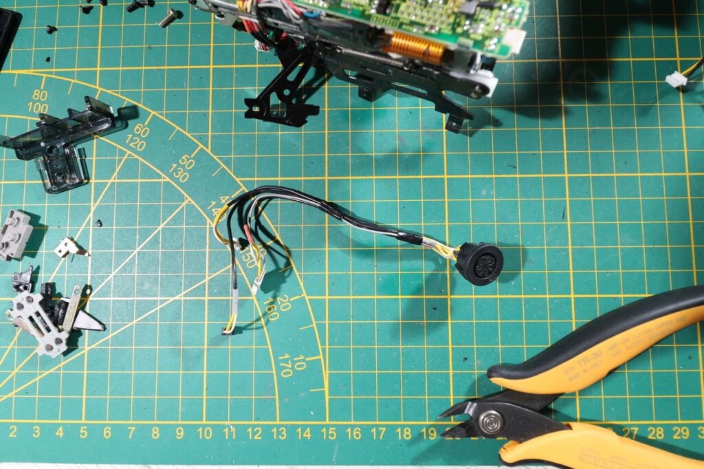
It was also almost impossible to take out the EVF plug – no way to access the second plastic tap that was holding it in. Initially I have tried breaking the plastic off so I could get a screw driver in to pus the tap. But I gave up when realizing that first I have to take out the DC IN plug which had accessible tabs. Long story short, I was also able to get the EVF plug out intact.
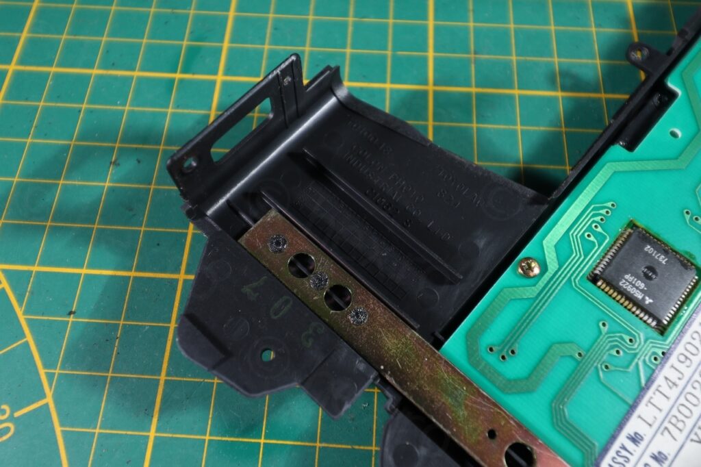
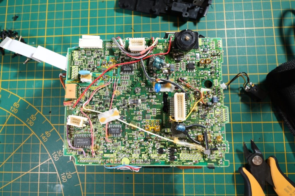
The bodges also showed that a lot of care was put intro trying to salvage the board. These boards have a human touch 🙂
EVF Unit
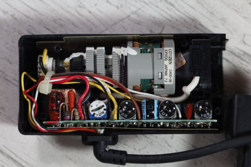
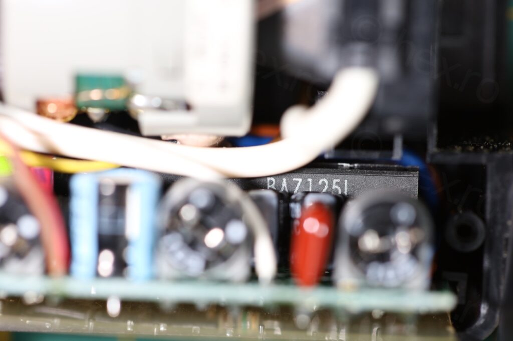
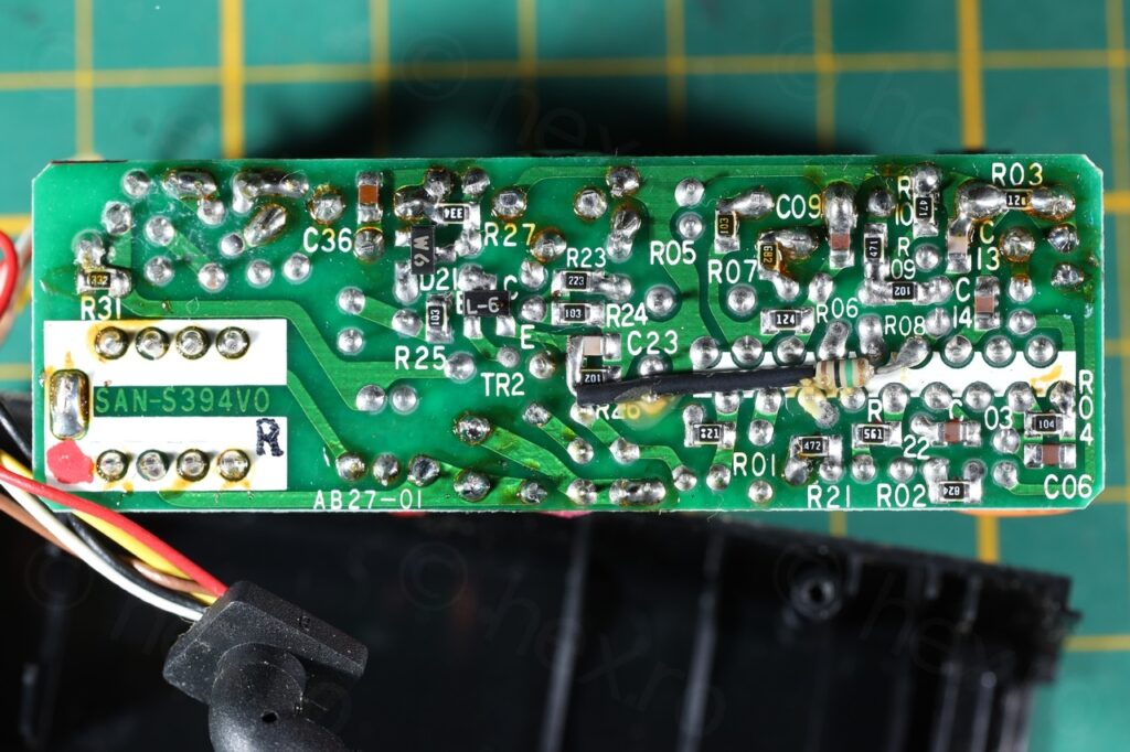
The board seems driven by BA7125L IC which is an odd IC that is mounted vertically, more like audio amplifier ICs. I was able to find the schematics of it, but I did not need them. The board matches the pattern I have already identified, GND is always connected to the metallic case of the Fly Back Transformer, then some of the pins of the FBT are connected directly to VCC. Then, no need to trace the Video In signal, as it can be found by trial and error.
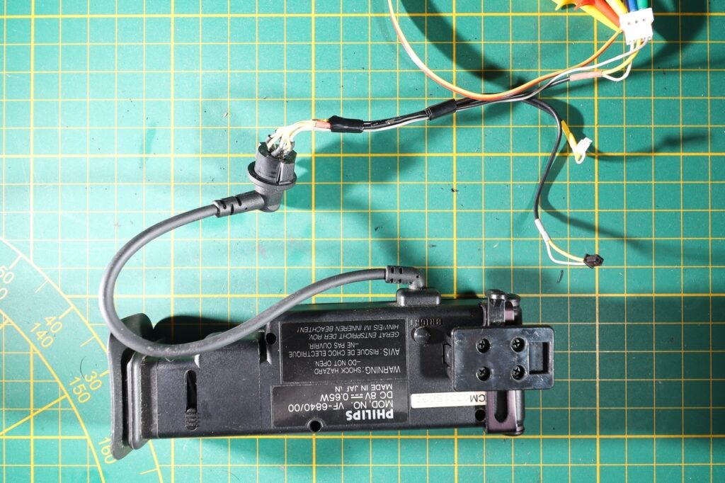
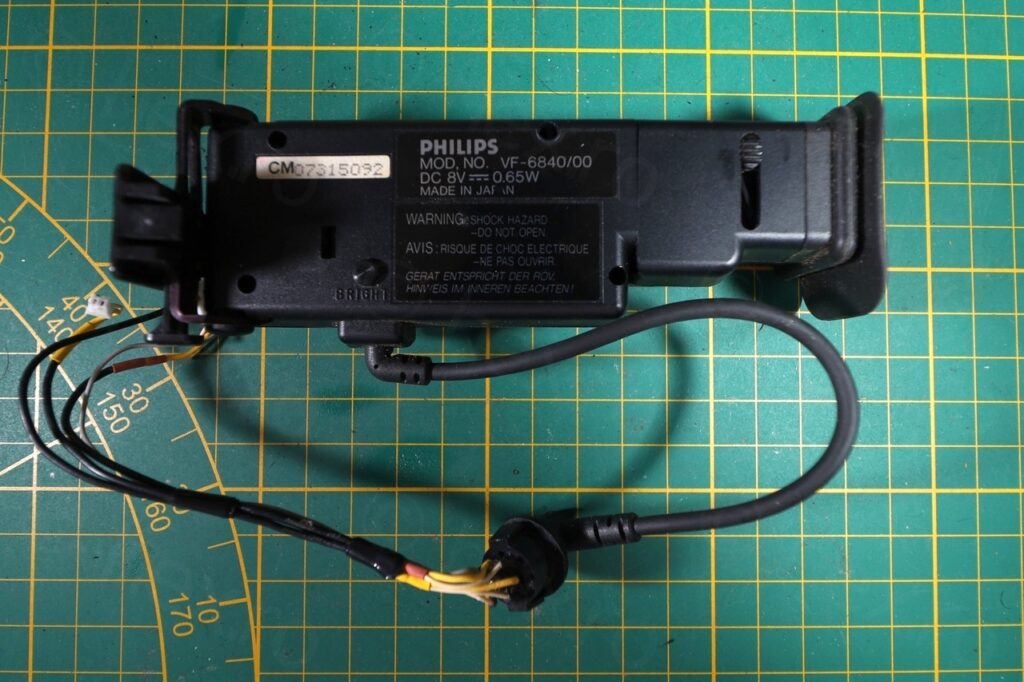
EVF unit with the plug 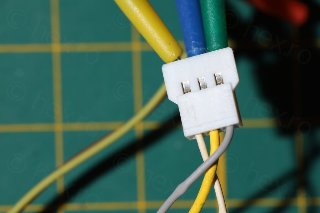
White – Video IN, Yellow is GND, Gray is VCC
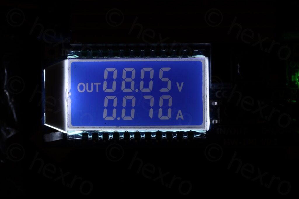
On the EVF plug that was taken out from the camera, the White wire is Video In, the Yellow wire is ground and the Gray wire is VCC. The expected voltage is 8V and it draws about 70mA:
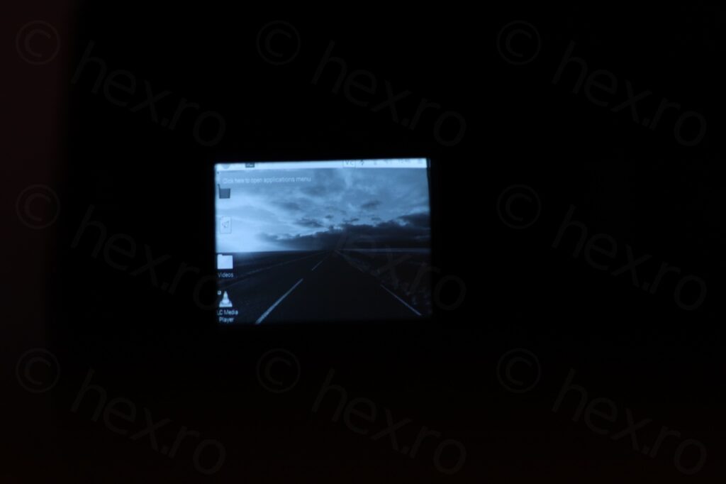
Long story short, the CRT works 🙂 and while very sharp and brightness is set correctly, albeit the geometry which is a little distorted.




Leave a Reply