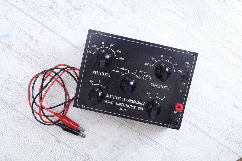


An interesting Resistance and Capacitance substitution box was hiding at a flea market.
I don’t find these type of devices often – I figured I should buy it. Not for using one (since I don’t really need it), but just because it would be cool to look inside and document it.
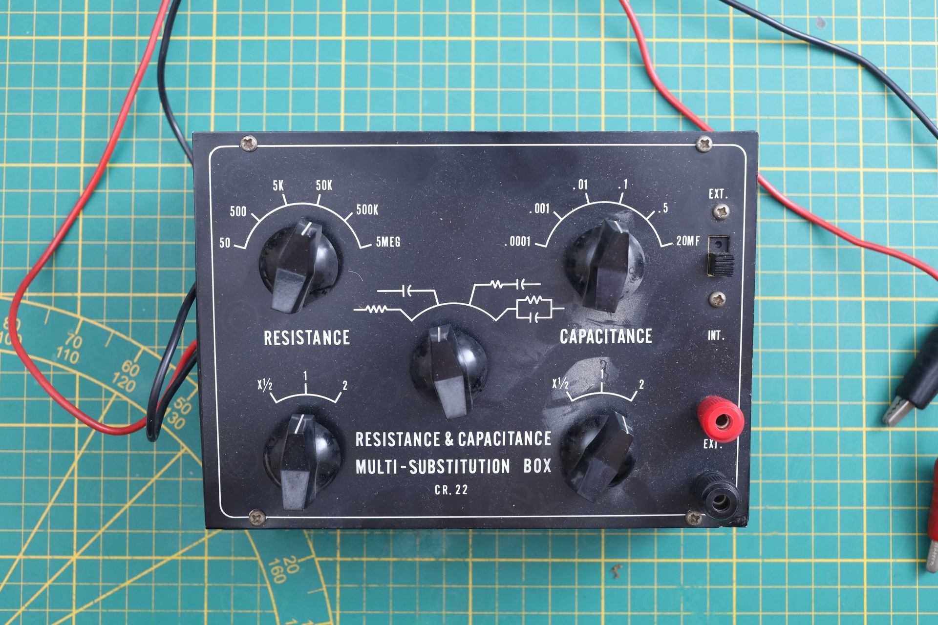
Overview
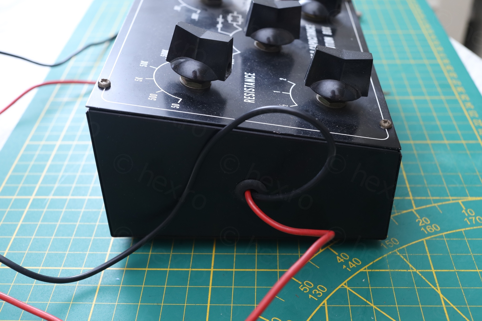
The box was dusty. The lower right corner (on the top plate) seem to have been bent and was straightened up (third photo), but without marks on the body itself ? Knobs turn exactly as you would imagine and even the original leads look good.
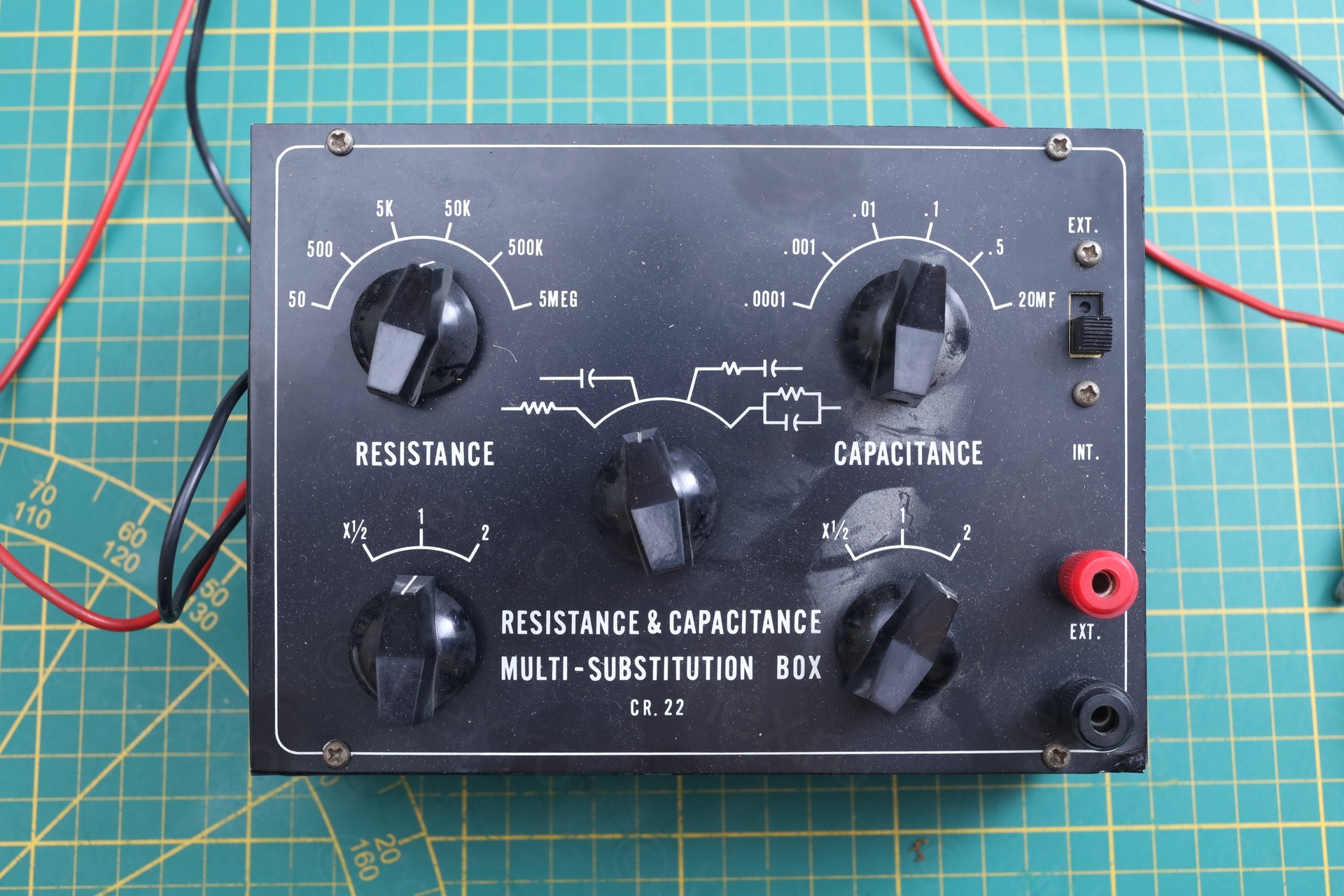
I proceeded to measure the Resistance part and it does work fine:
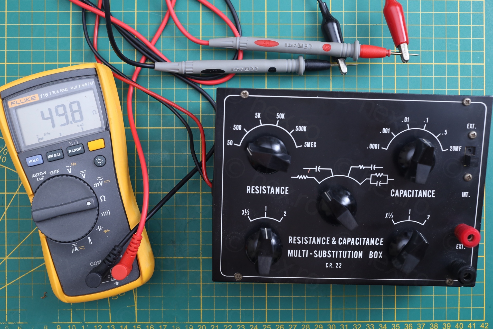
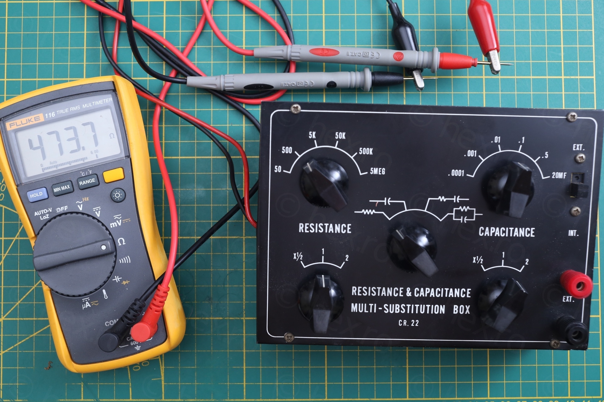
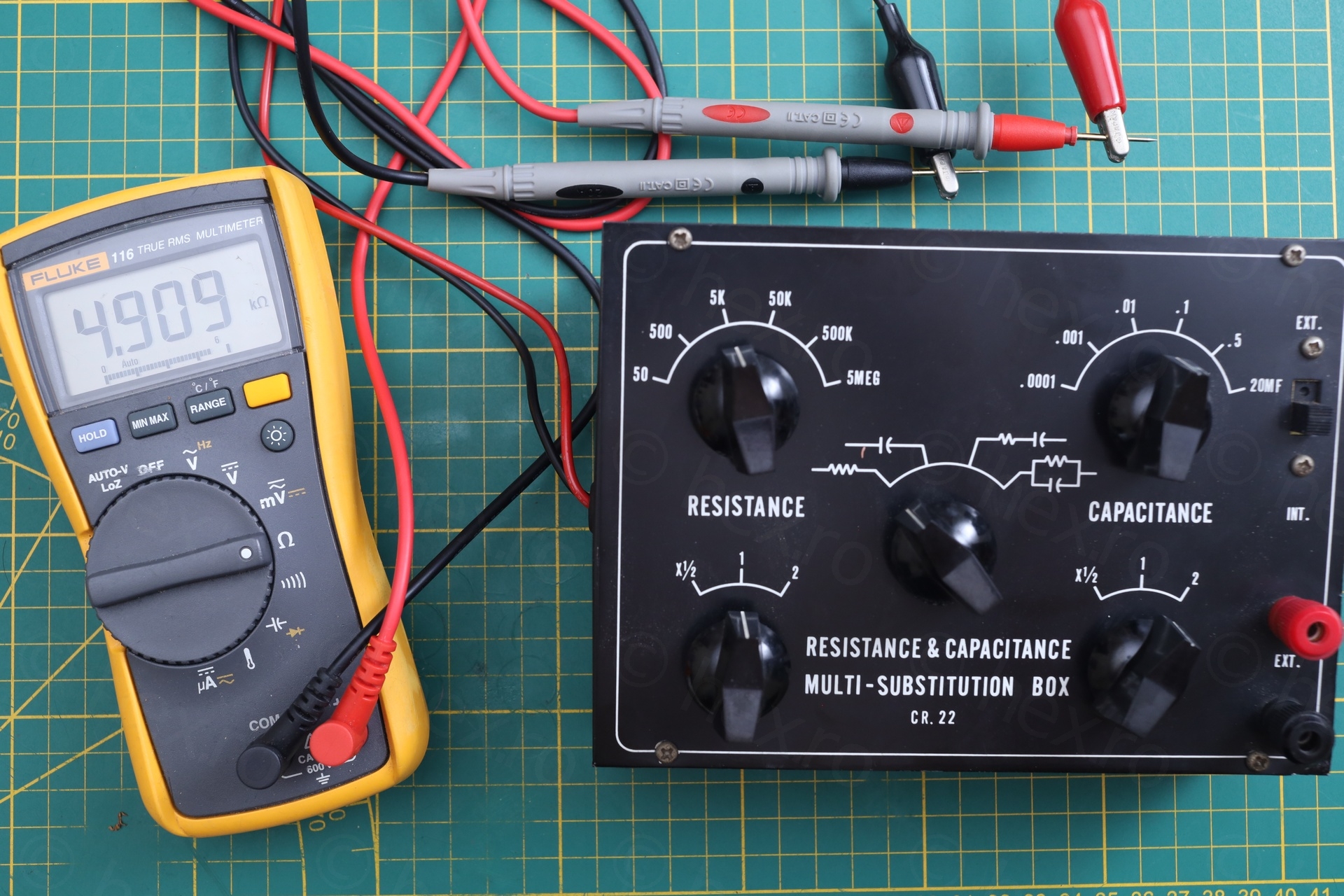
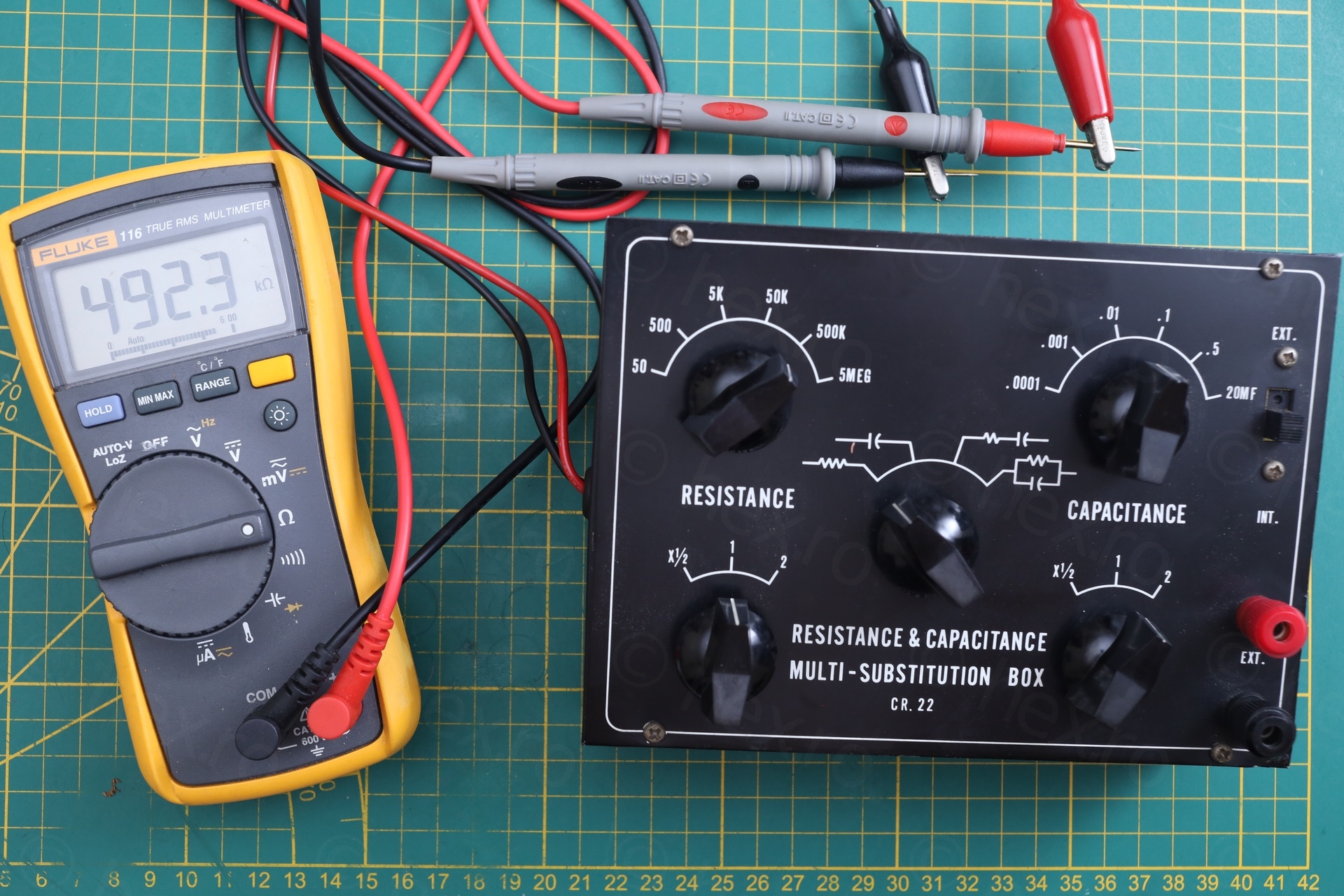

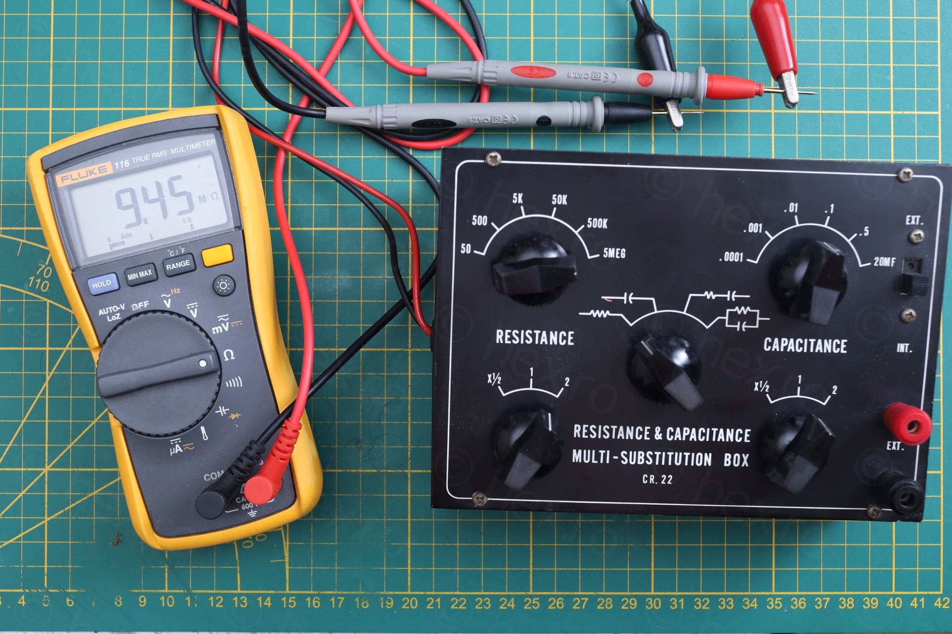
9.45MΩ for 5MΩ x 2 multiplier
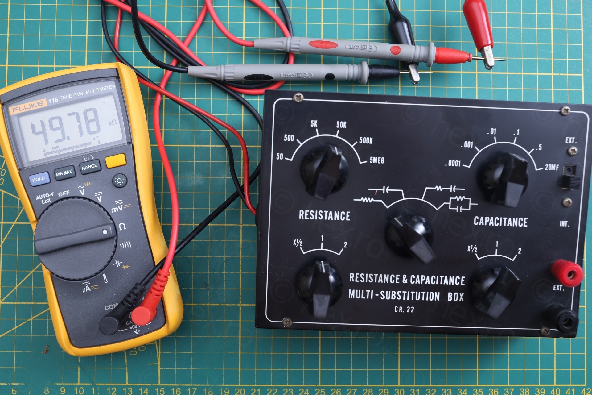
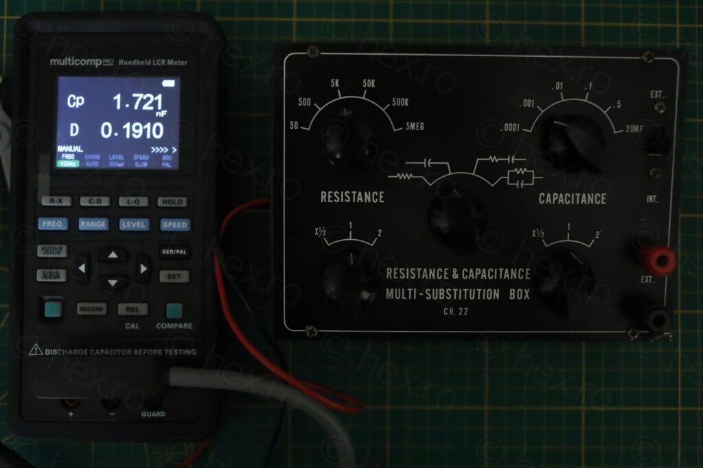
However, Capacitance side was not behaving properly at all:
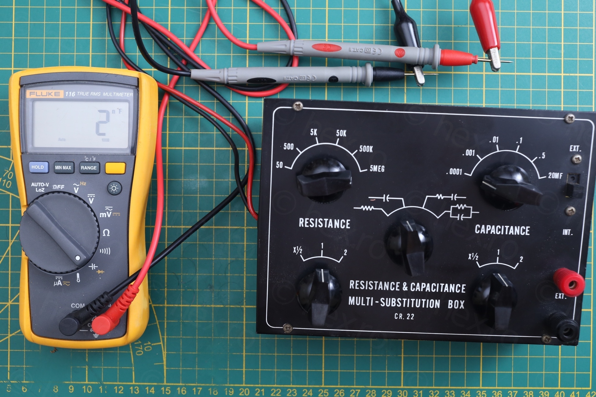
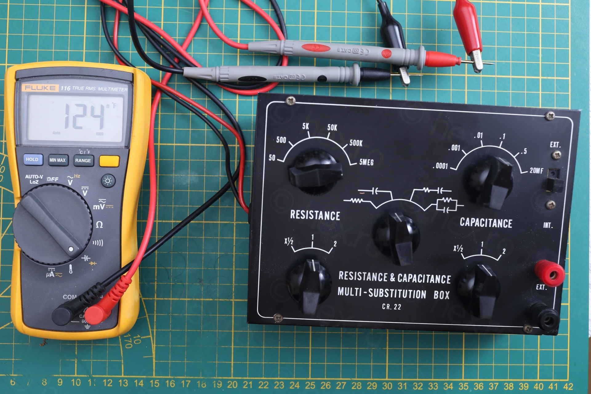
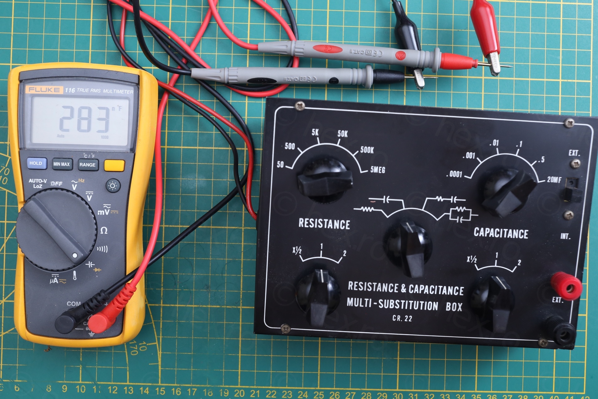
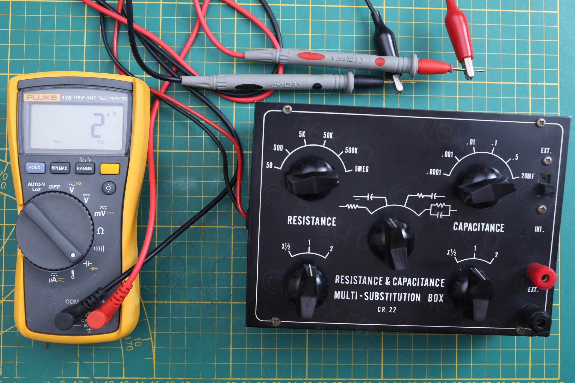
This was disappointing … the only value that got closer was the 100nF (which Fluke Model 116 was showing as 124nF), but none of the others were actually making sense. This gave me impetus to get inside it, while promising myself to swap the dead capacitors and make it work.
You may notice that I have already made an assumption. That the capacitors were dead. This turned out to be wrong, but it costed me time and money. But let’s continue.
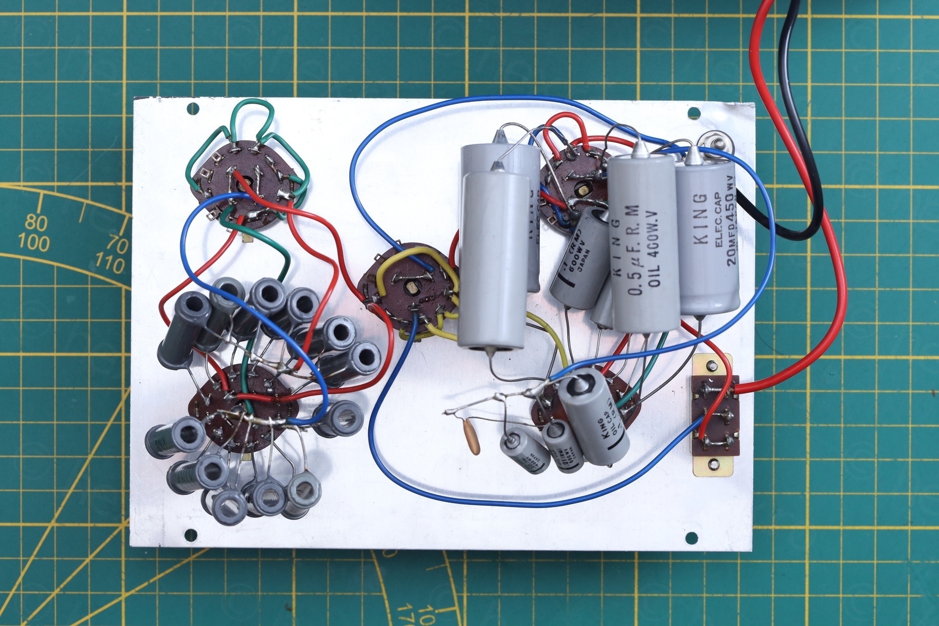
Inside the Box
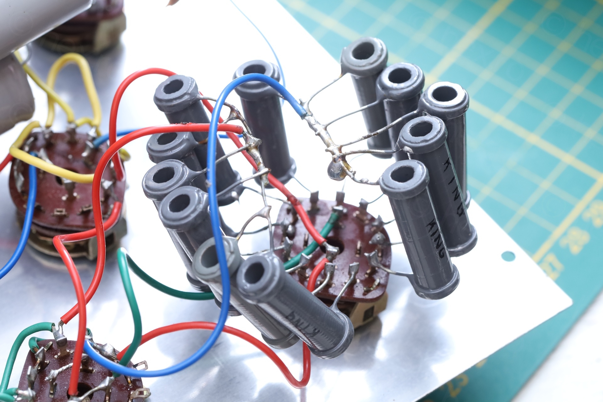
Decided to open up the box and have a look around. Found a special selection of parts, all King capacitors and resistances! Felt bad I have to throw away the capacitors.
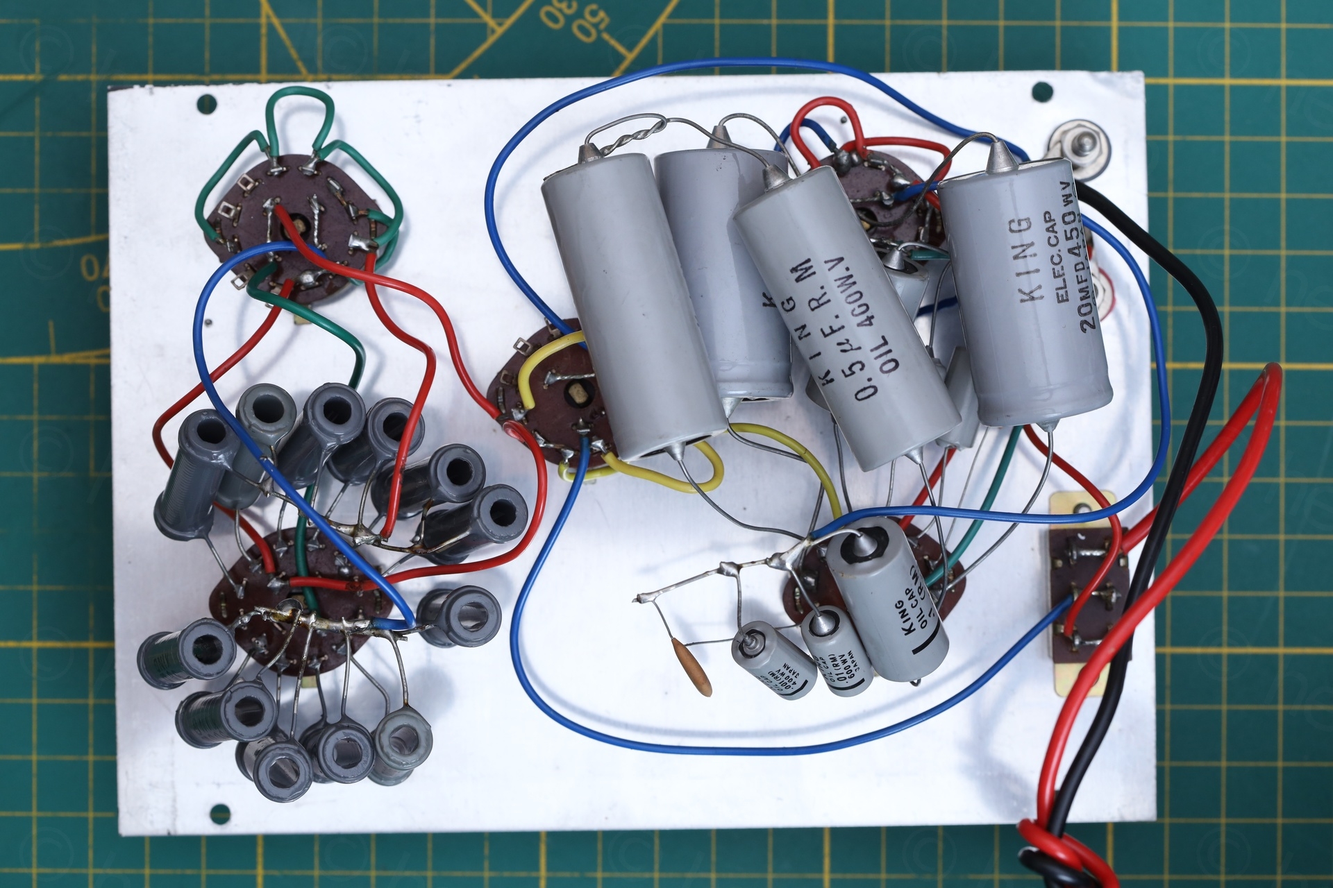
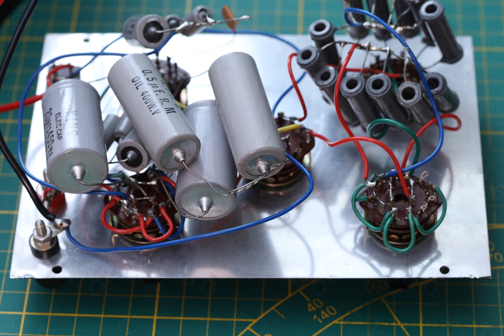
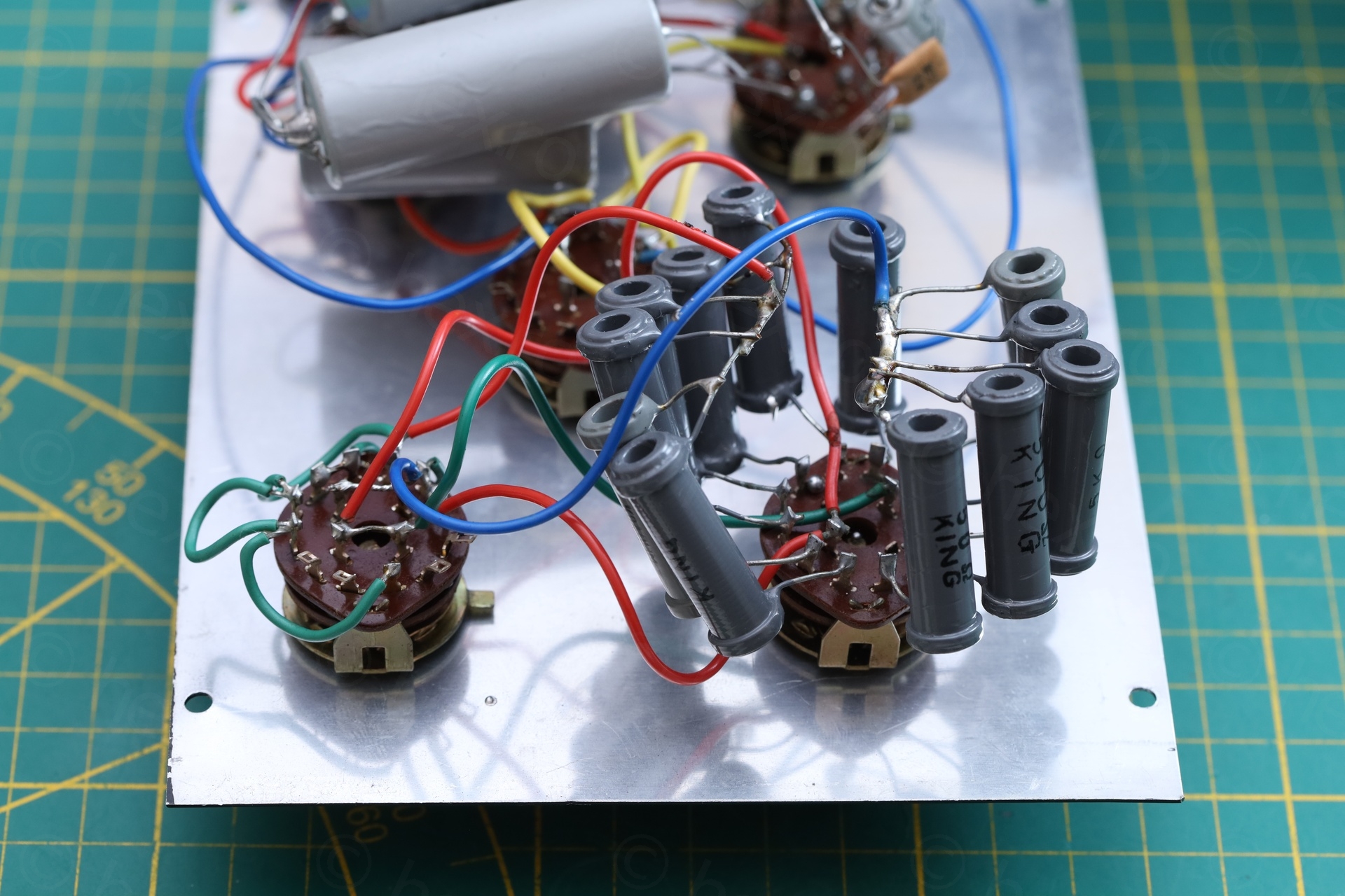
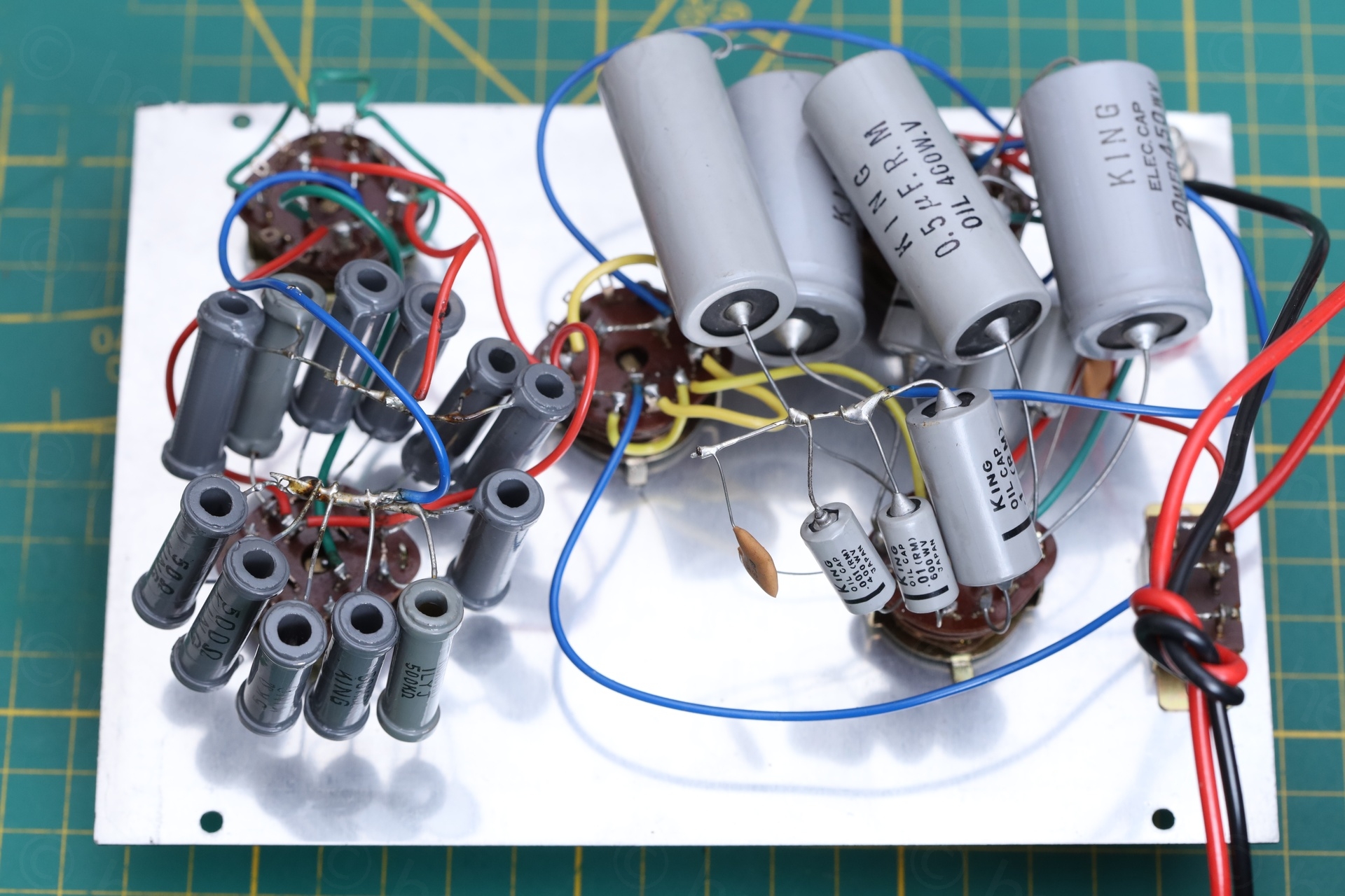
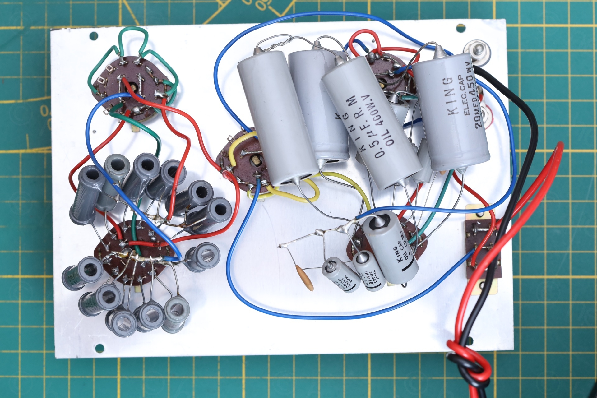
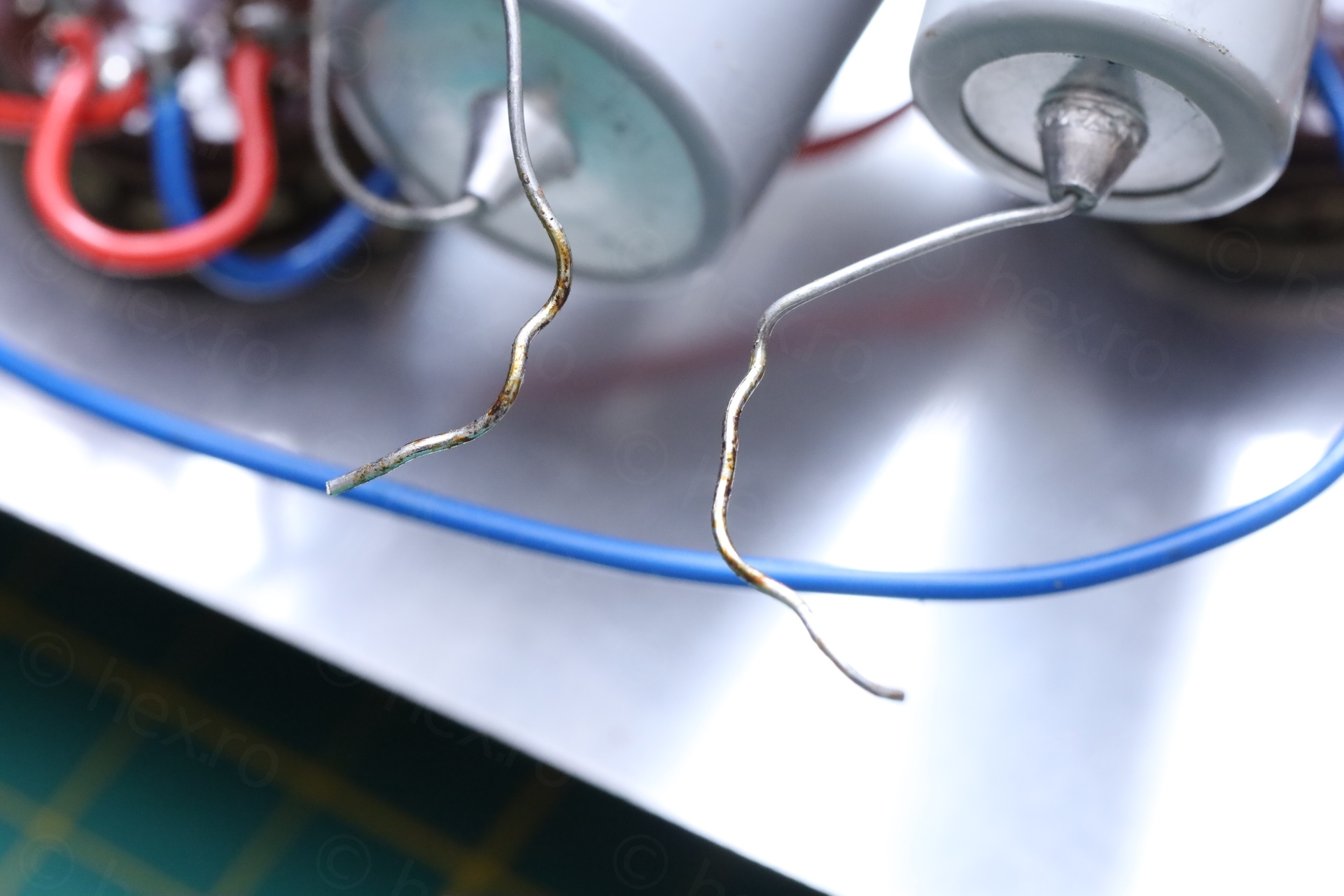
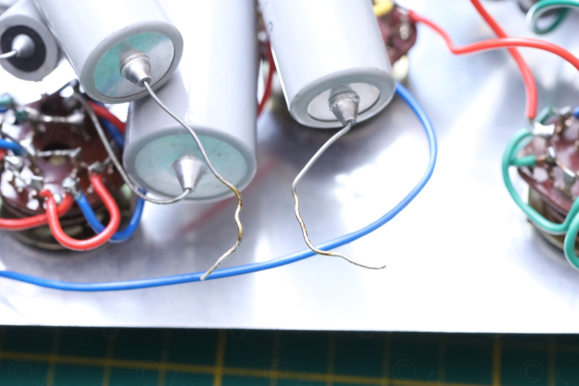
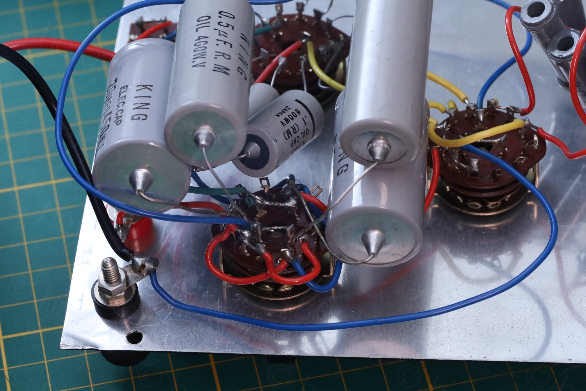
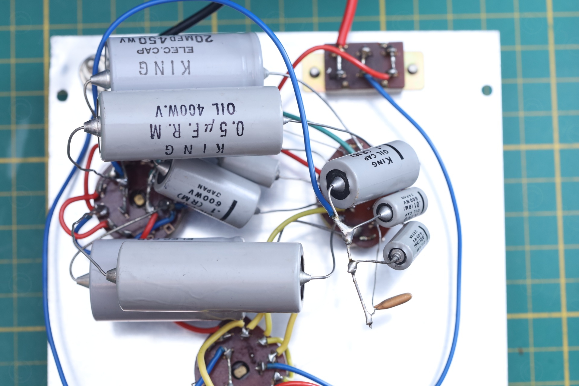
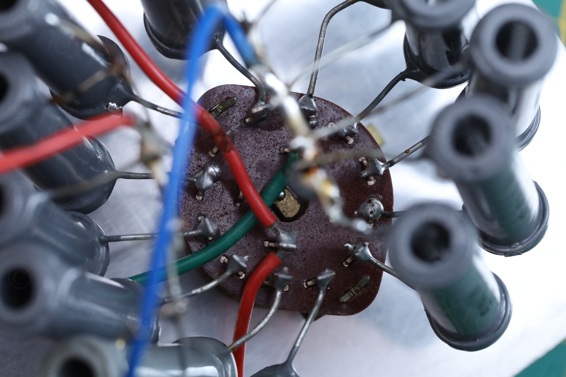
Having a look around, something looked amiss. One of the large capacitors had a floating lead:
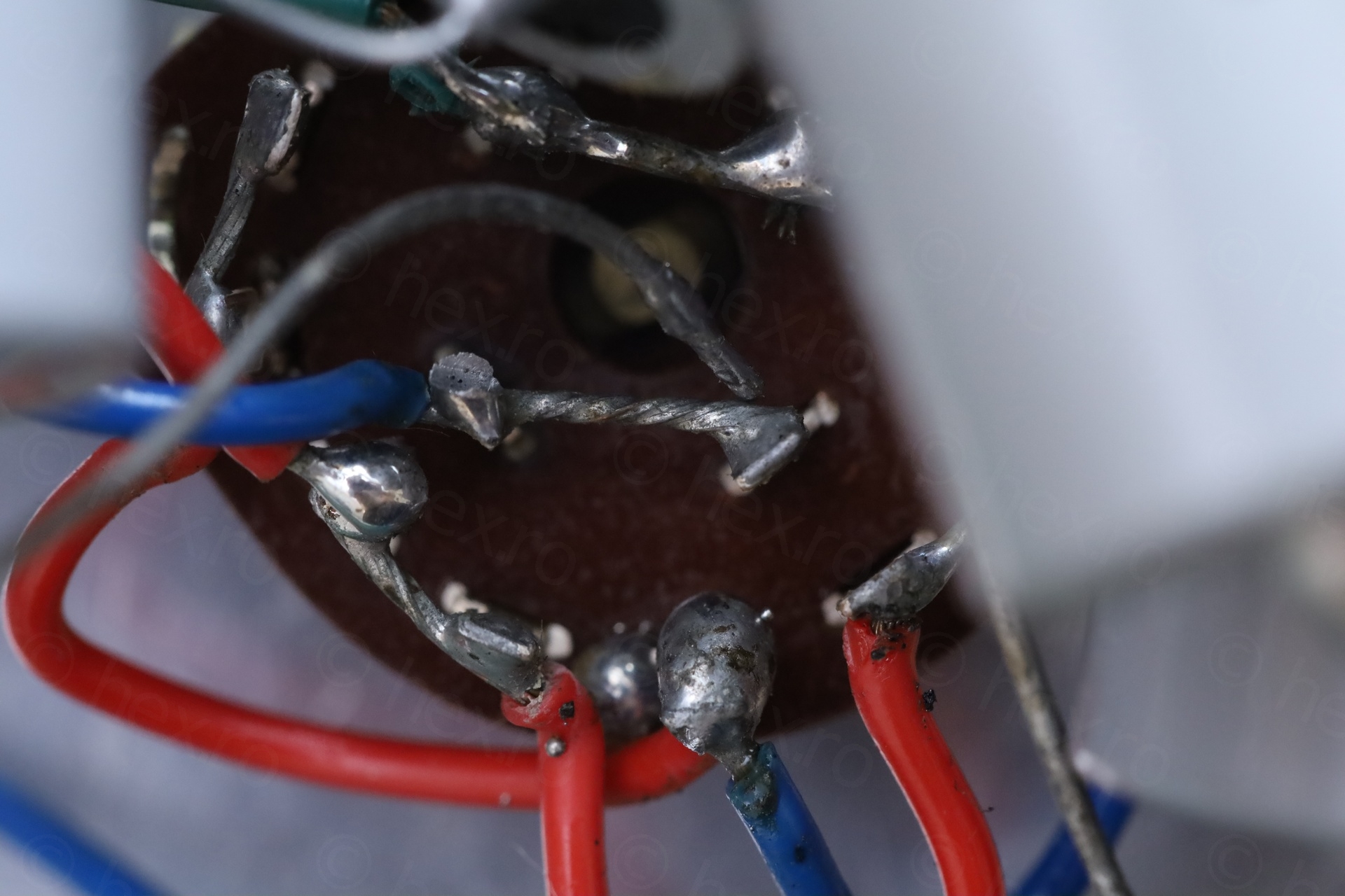
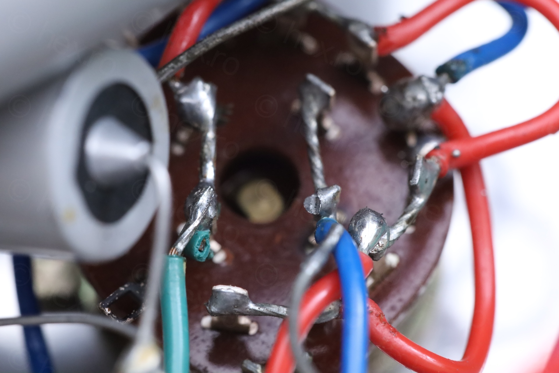
And two more hand their leads twisted together, which didn’t make sense – why would they be “hardcoded” in series directly, when they should have been soldered to the knob ?
At this moment I blindly ordered capacitors replacements.
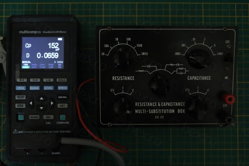
Once the parts arrived and getting ready to start swapping, I realized I need to make a map of the polarity +/- leads of existing ones so that the new ones go in correctly. And surprise surprise. No markings! Original ones have no markings and seem to be Oil Filled – which are non-polarized. Pffffff… what a beginner mistake. Oh well. I kept reading about Oil Filled capacitors, few opinions being that they age well and most likely not bad. That’s when I decided to take a better LCR meter out and see what I’m up against.
Long story short, they are all fine..
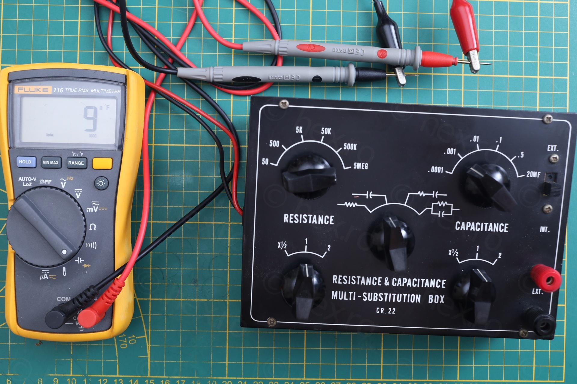
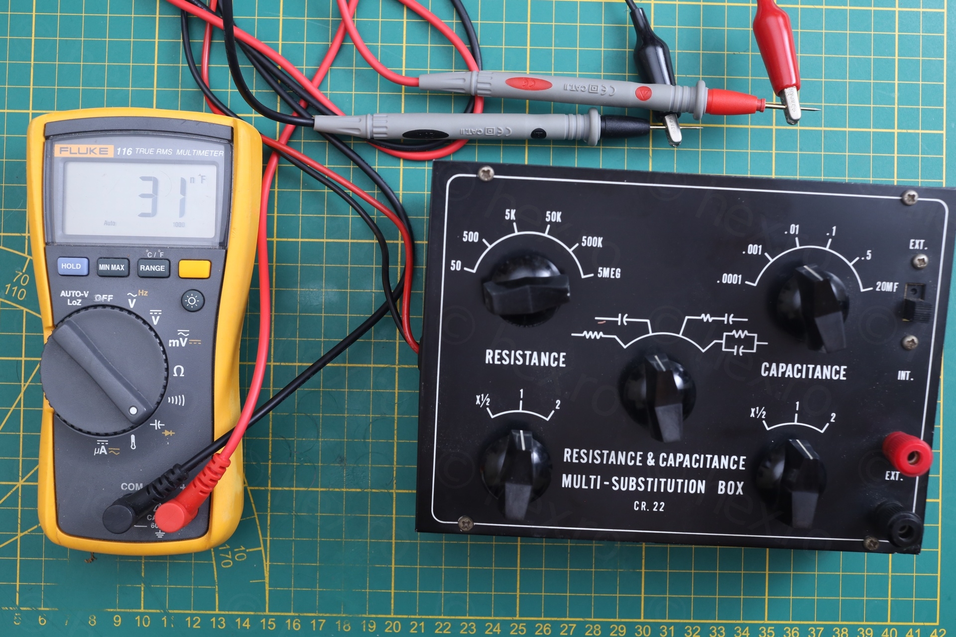
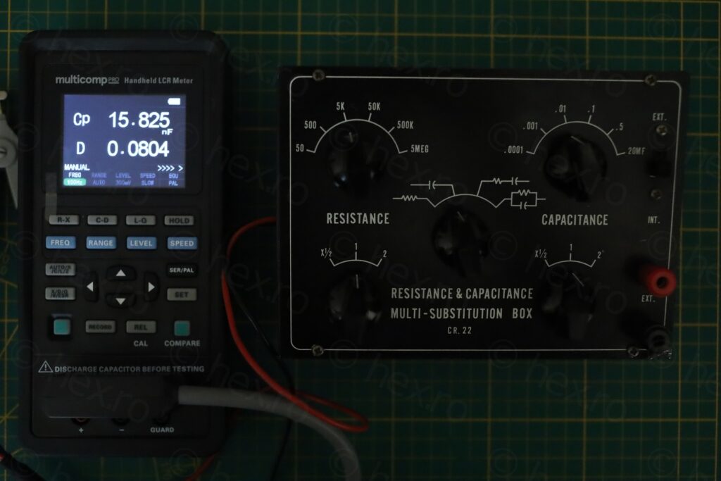
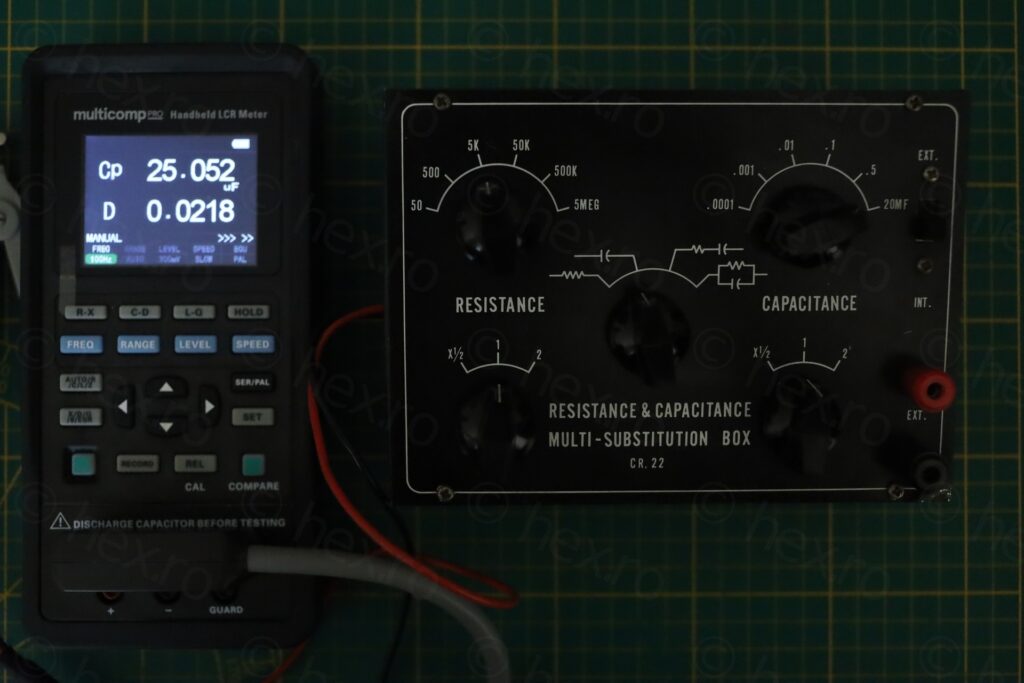
I was confused by Fluke 116 reporting the 10nF setting as 31nF. I do not know how Fluke measures low capacitance (or maybe my meter is broken and I don’t know?). But the Multicomp Pro MP700434 LCR Meter reports the same capacitor at 15nF (measured at 100Hz).
Fixing the box
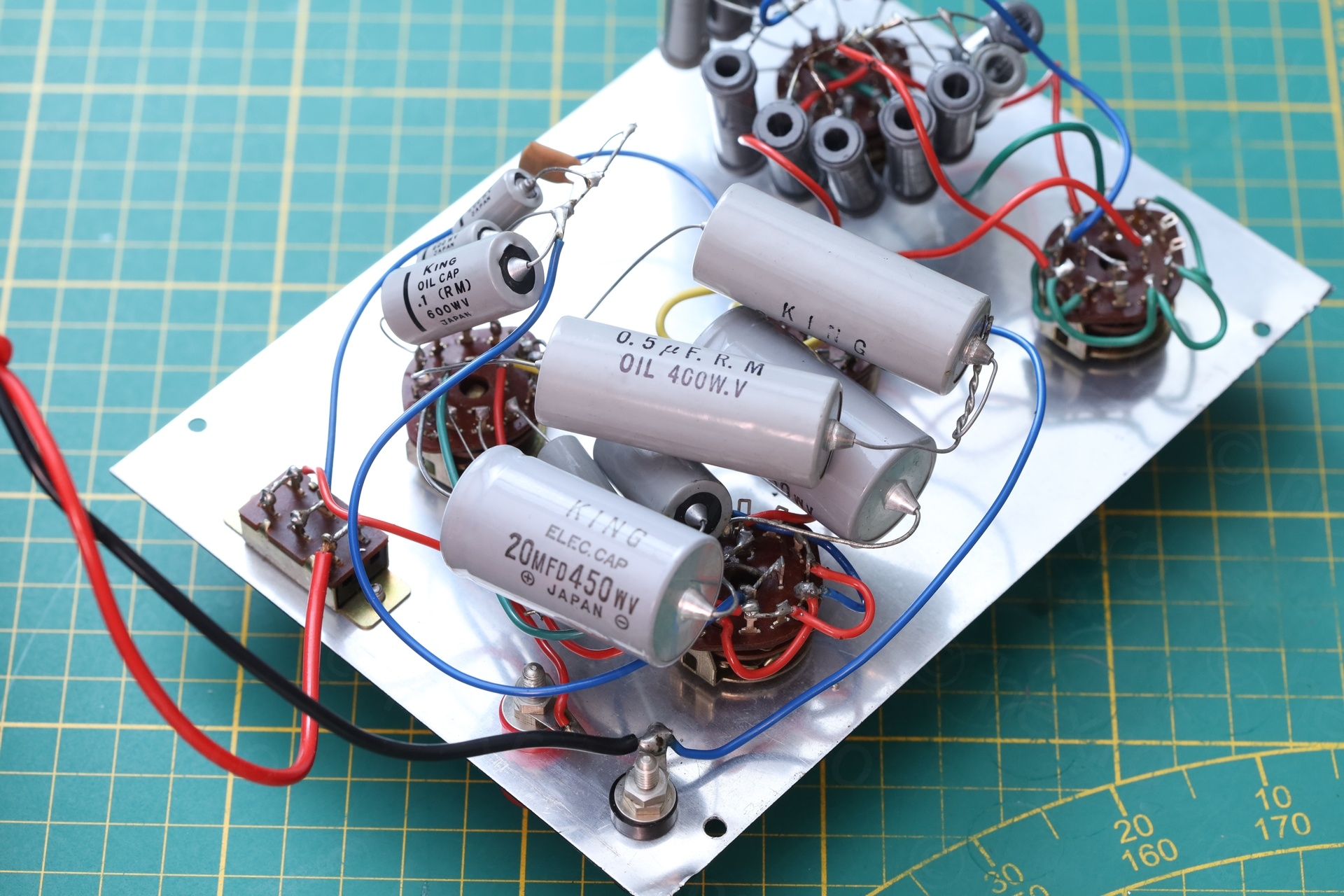
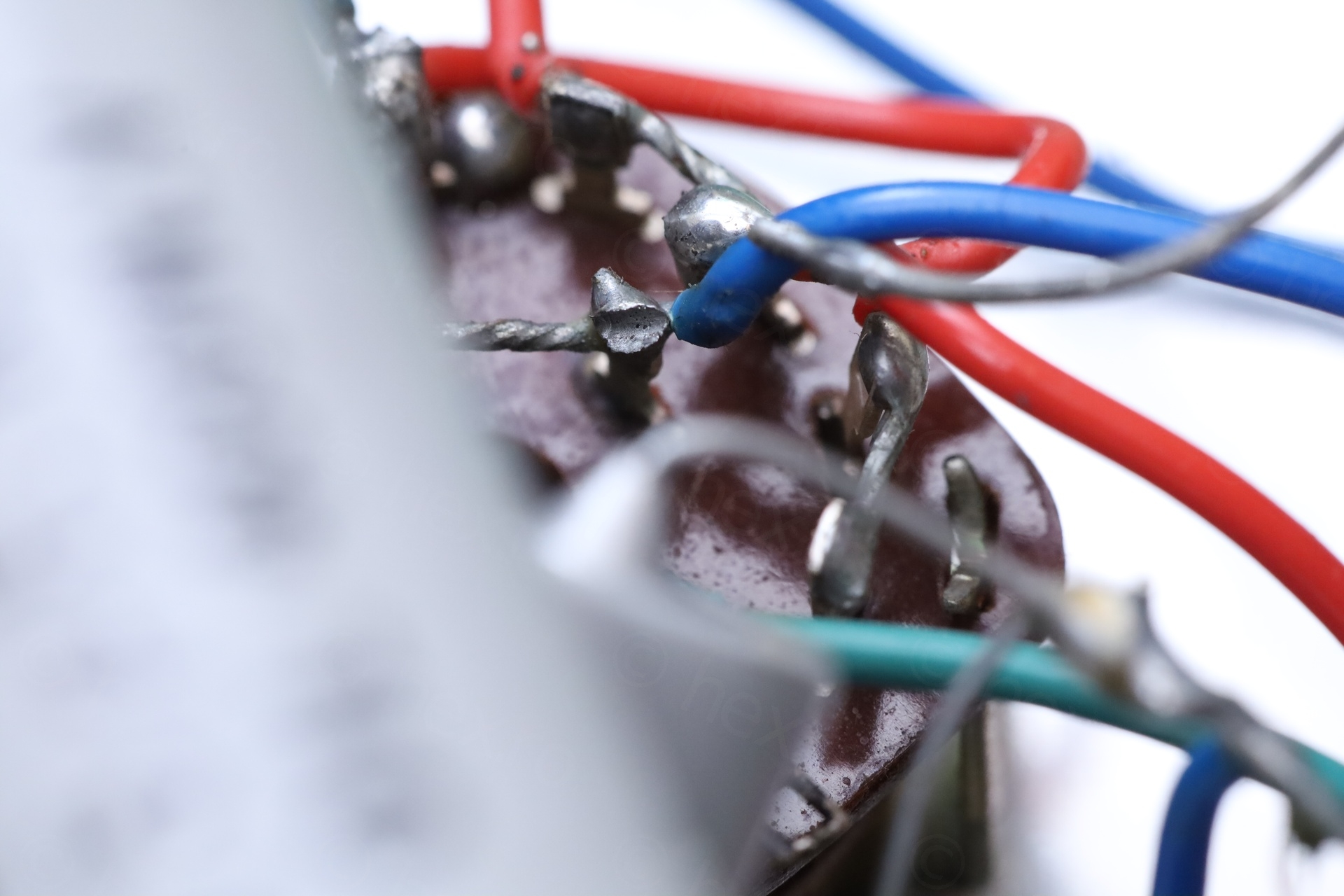
Relieved I can keep the box with original parts, I proceeded to re-solder the floating leg of one of the capacitors, and untangle the leads of the two other ones.
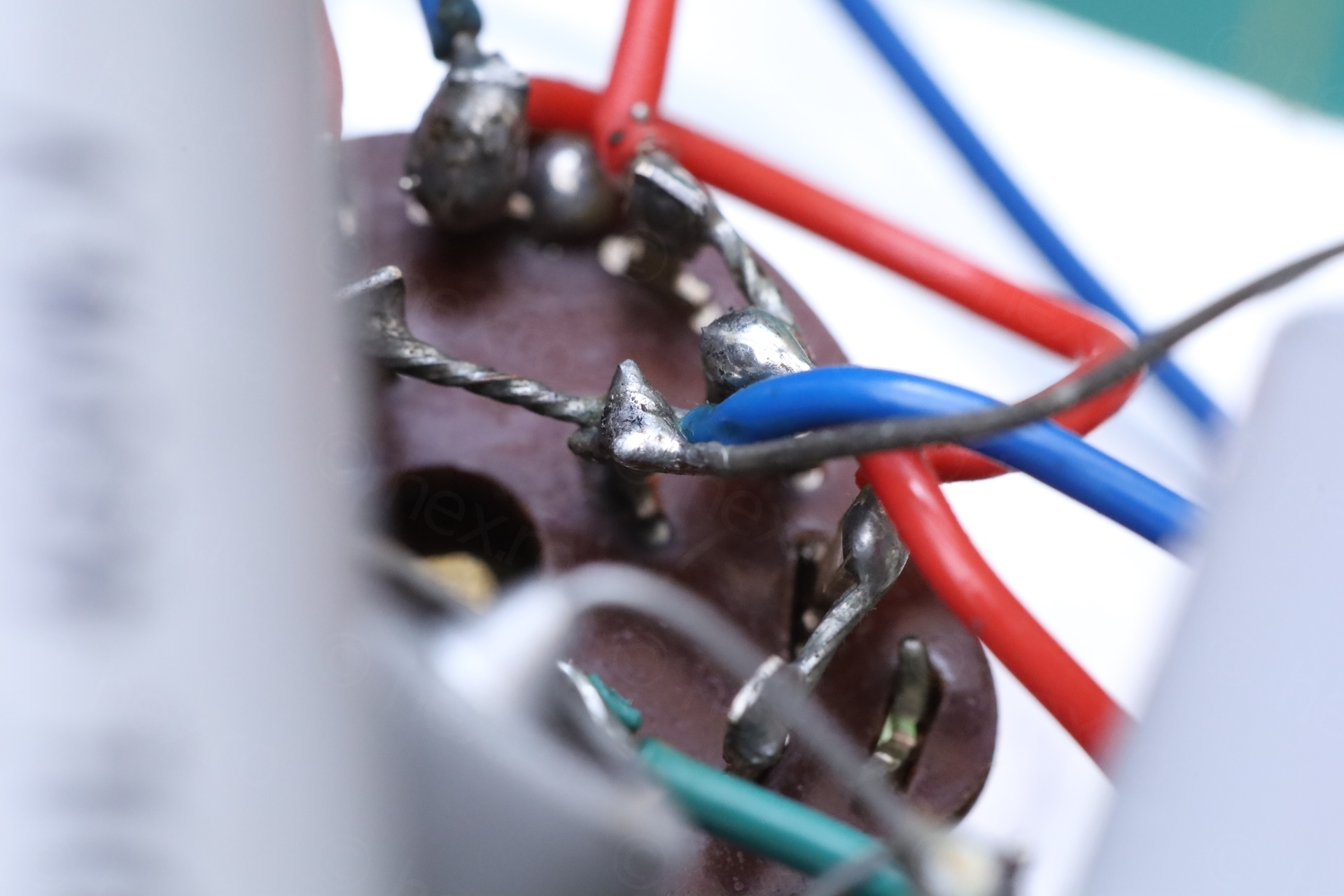
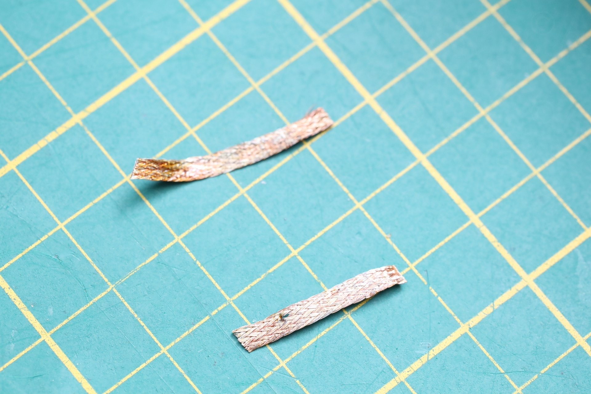
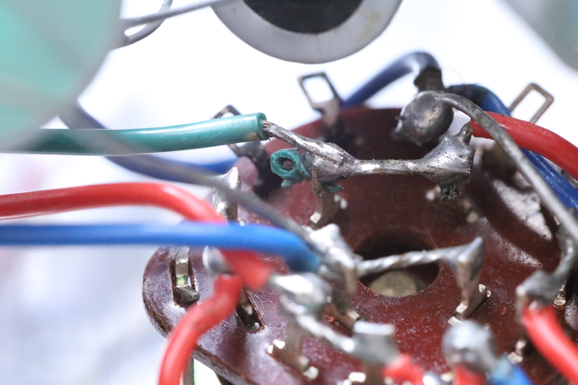
Untangling twisted solder leads was difficult. I got burned few times trying to quickly pry the leads away one from each other, millimeter by millimeter. The goal was to save the leads. It was way easier to cut, but … if they can be salvaged, then ok.
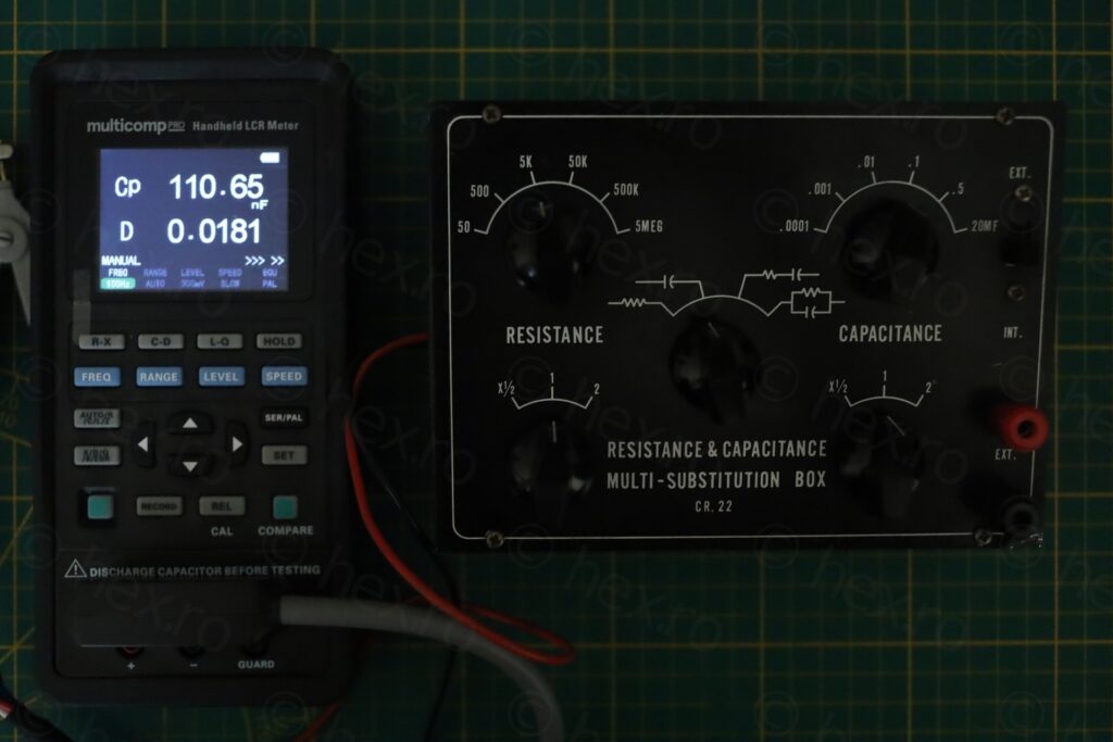
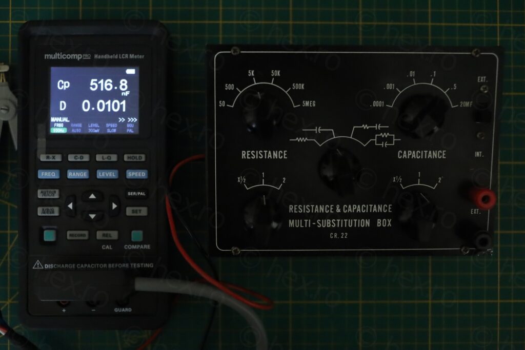
Results at 100Hz:
I was so focused on the capacitors, I almost forgot to post a pic of the resistances:
A nice rewarding device – at least it still contains all original parts, now correctly re-positioned.
Leave a Reply