
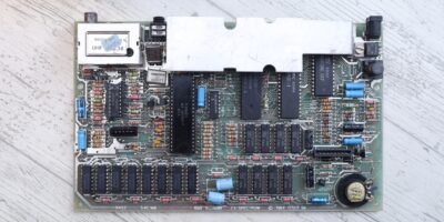
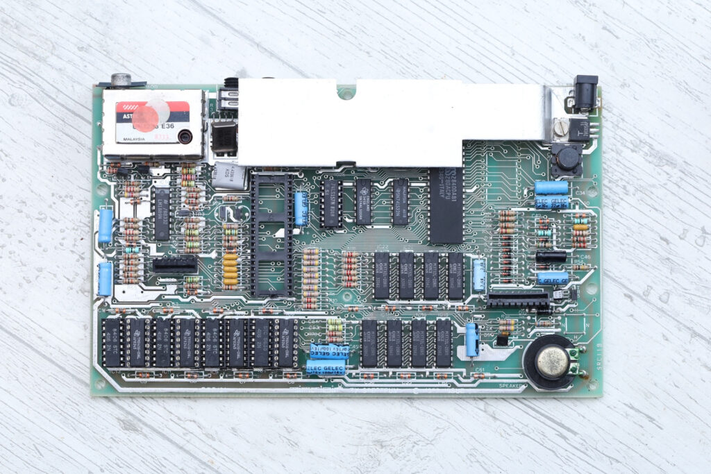
Got this motherboard at an online sale. At first view, only the ROM chip was missing. I was hopeful that it was just taken away and that the board still works.
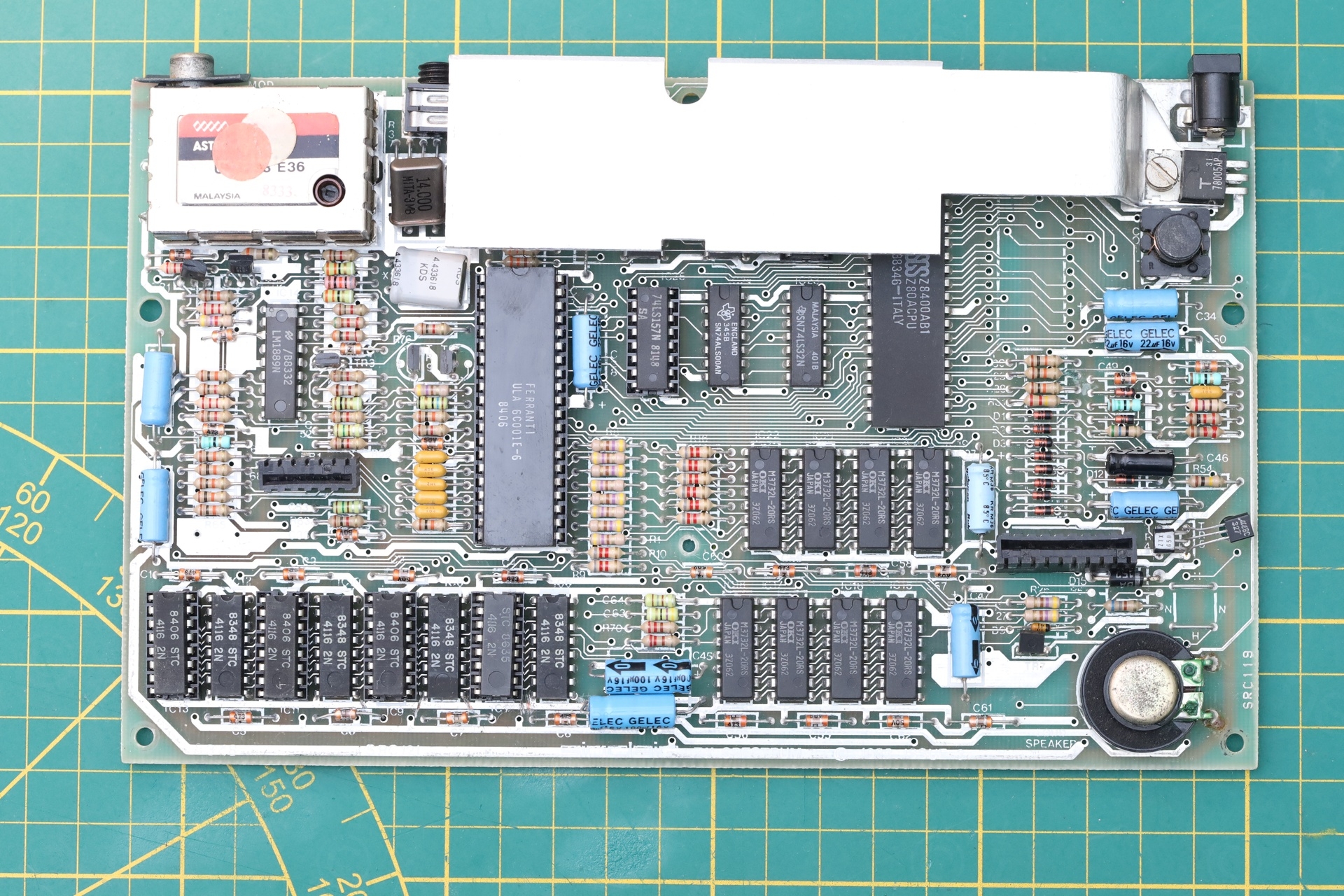
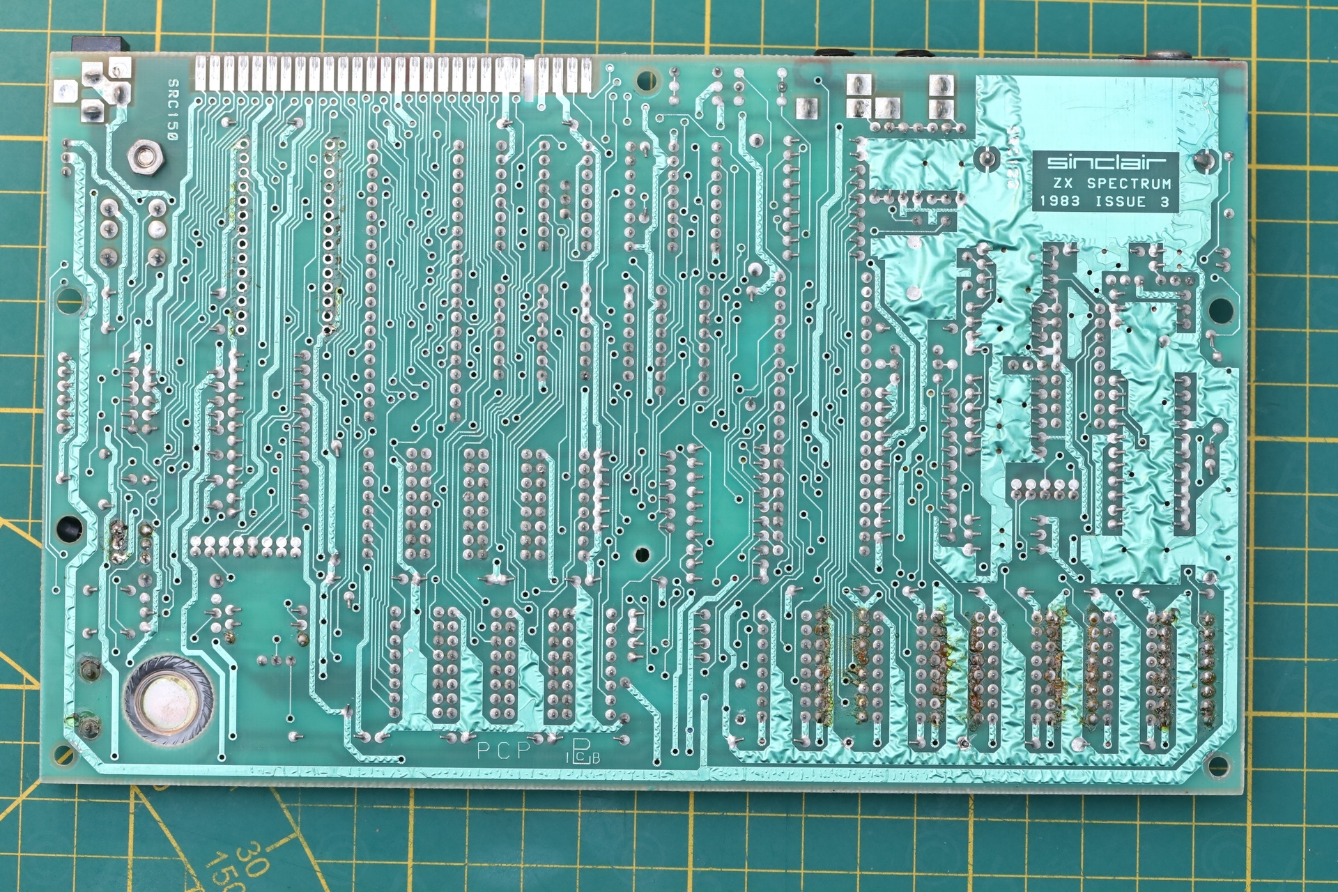
On closer look …
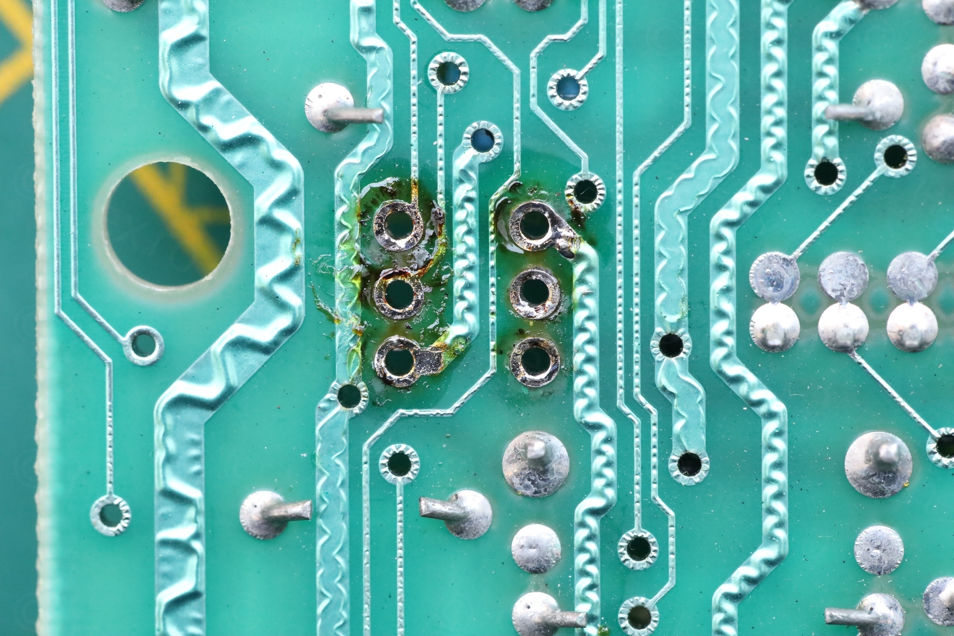
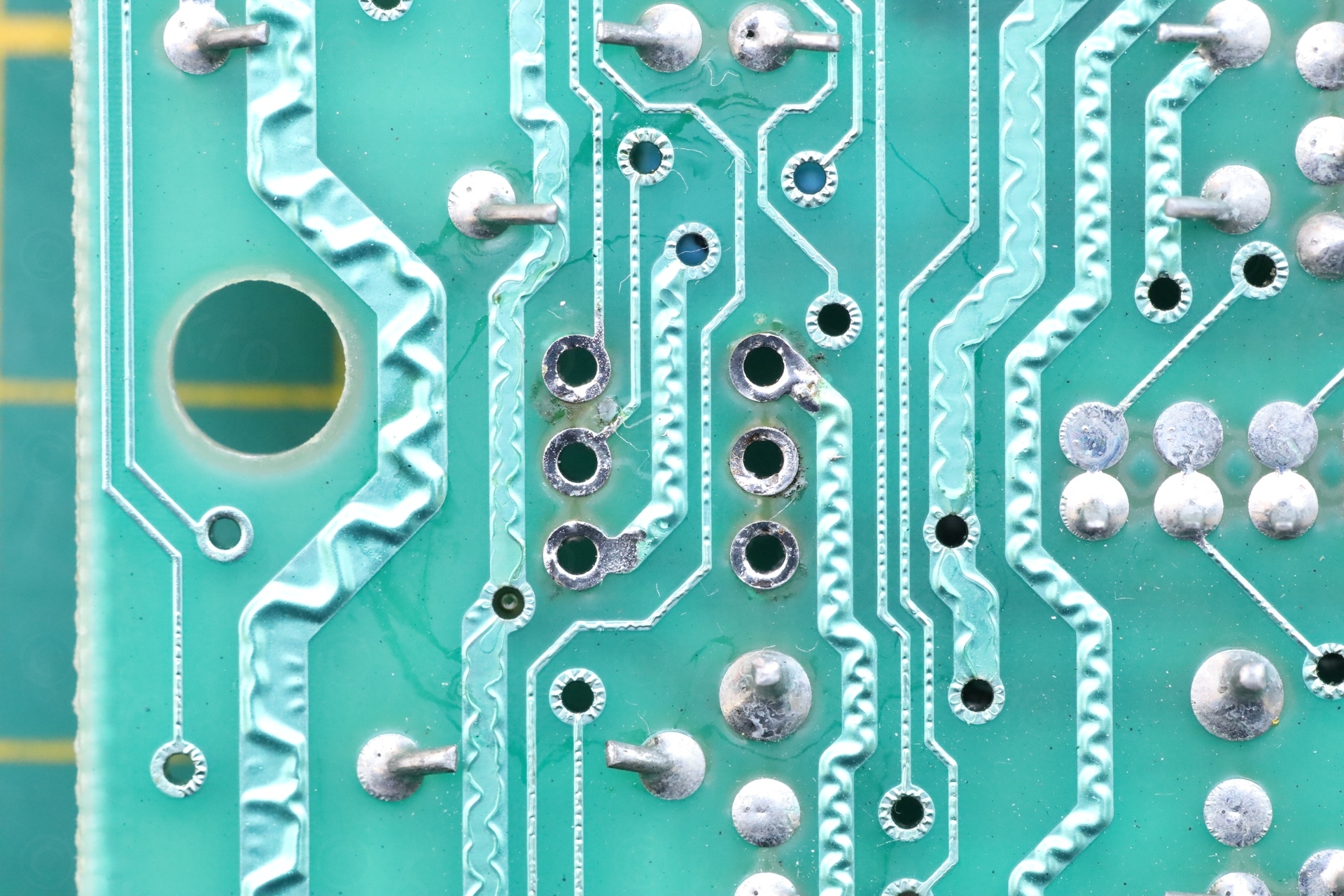
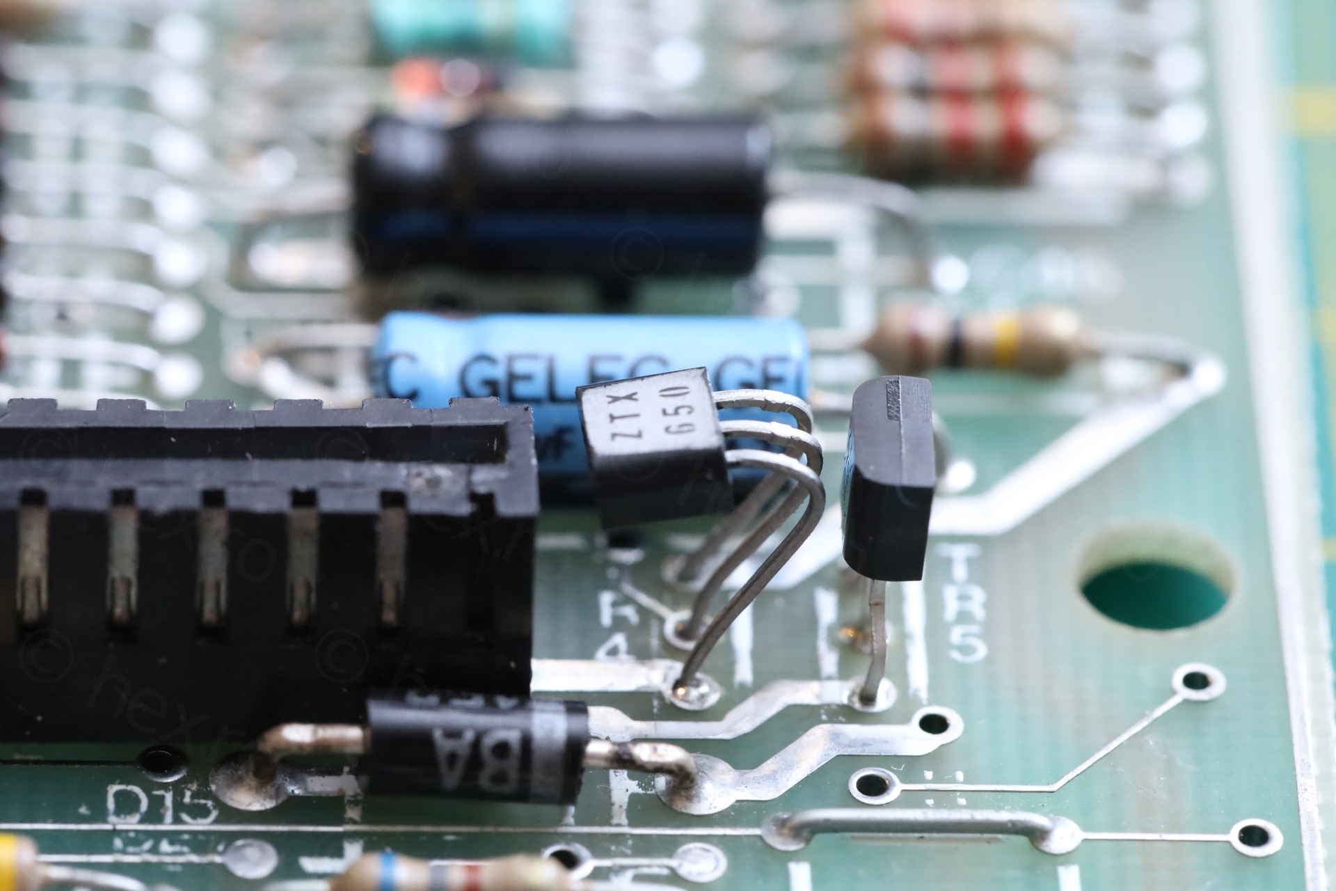
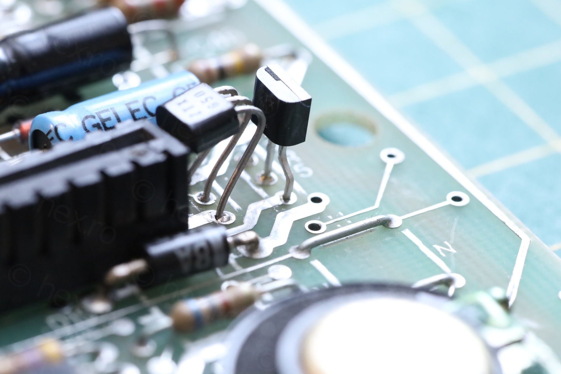
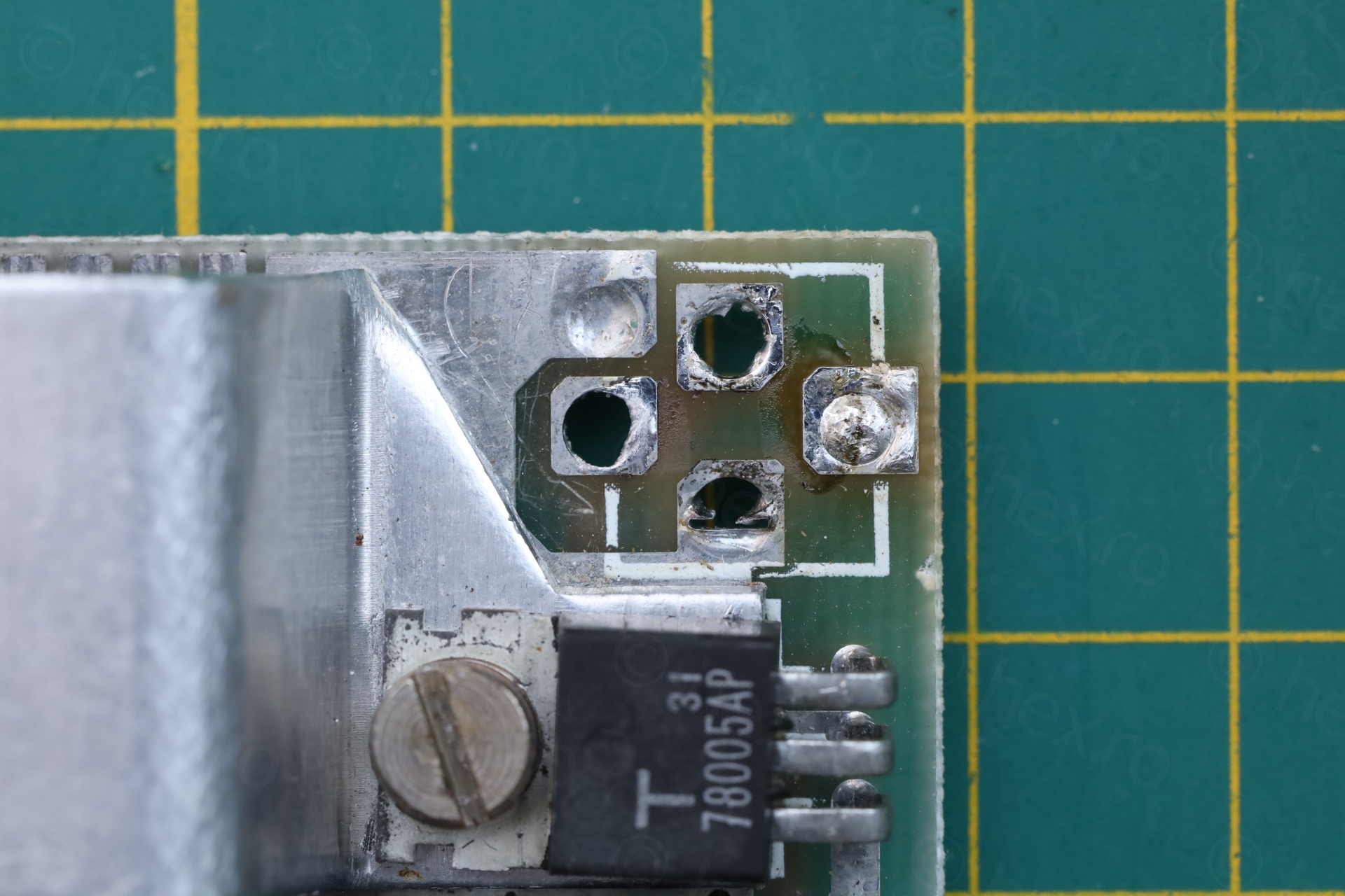
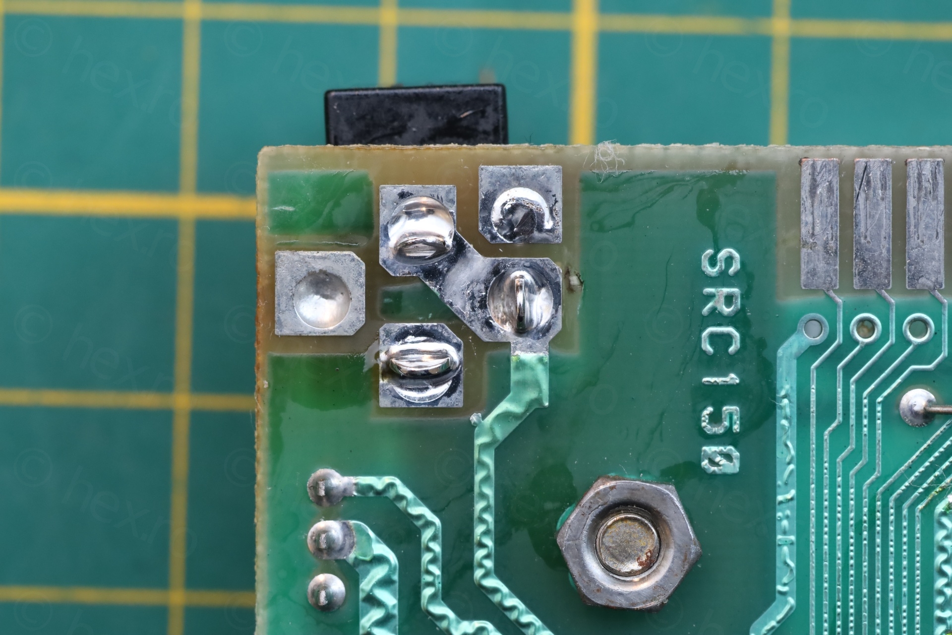
a) Signs of work on the TR4 / TR5 – they were re-soldered:
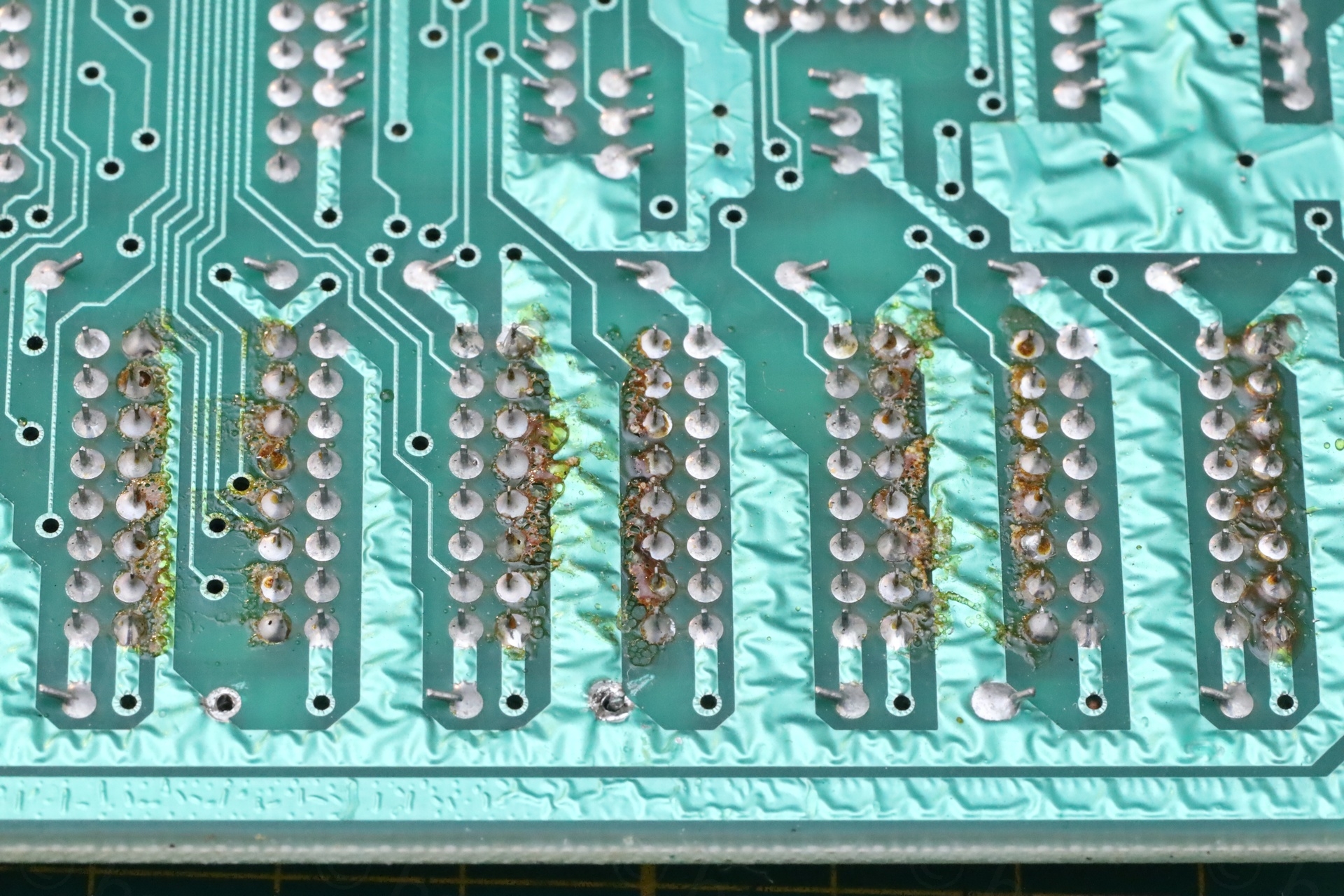
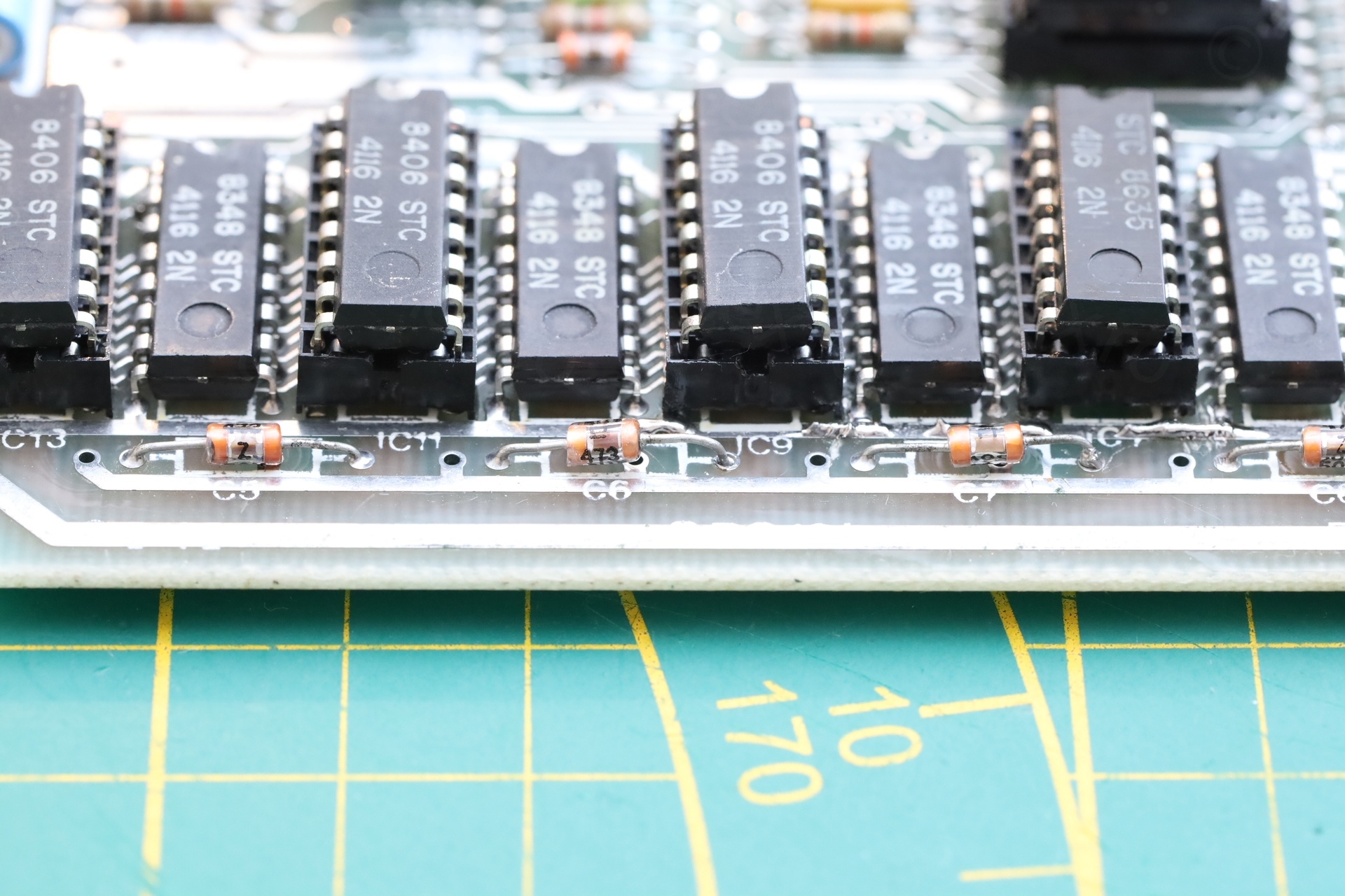
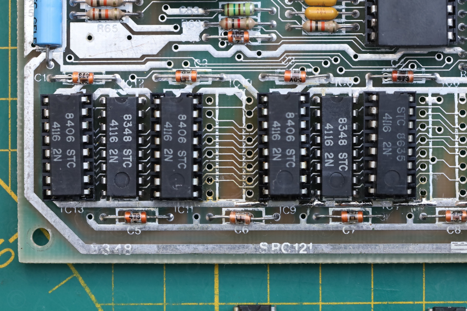
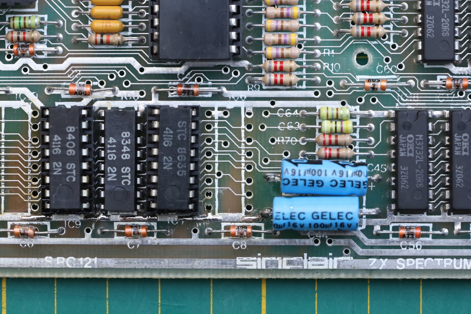
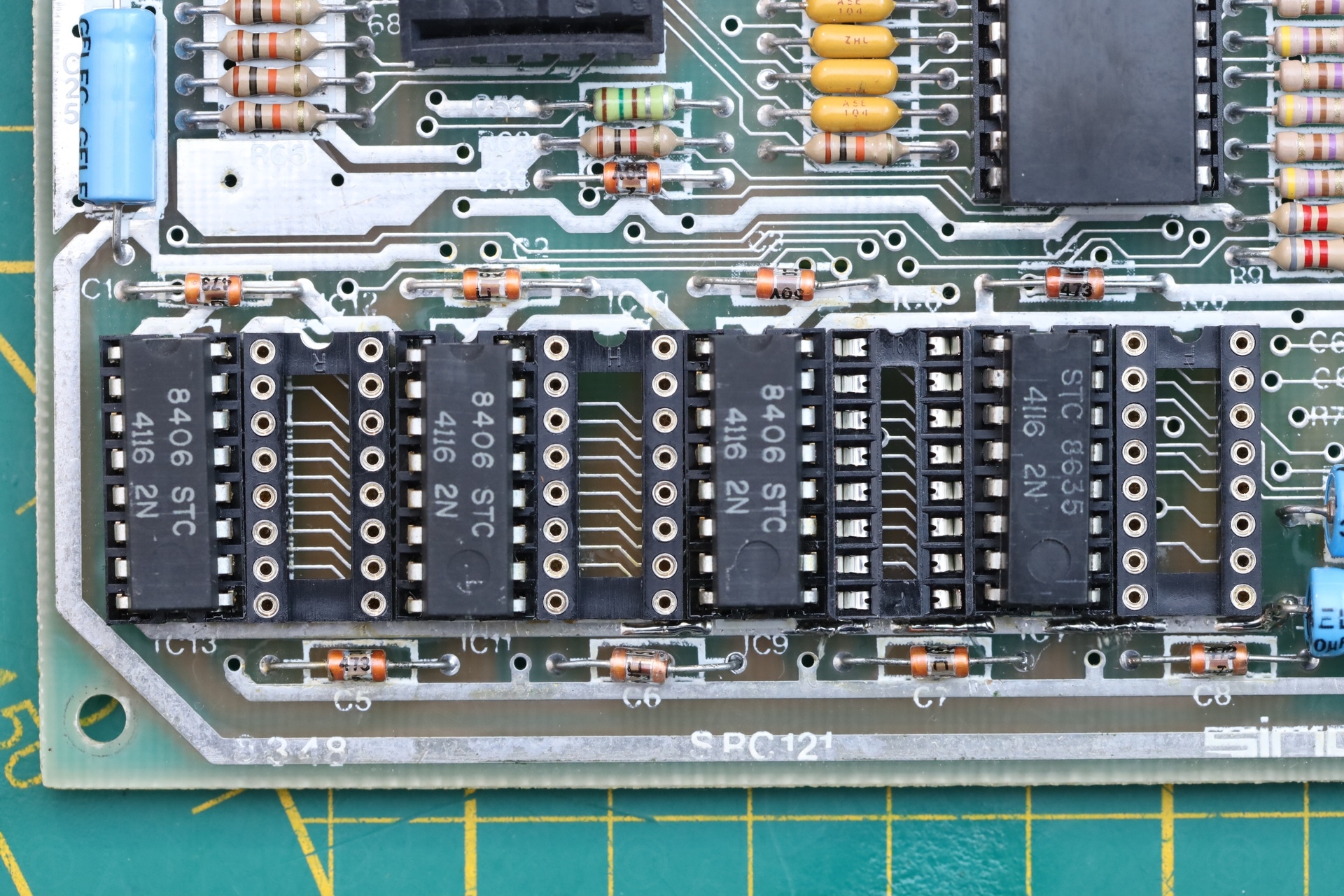
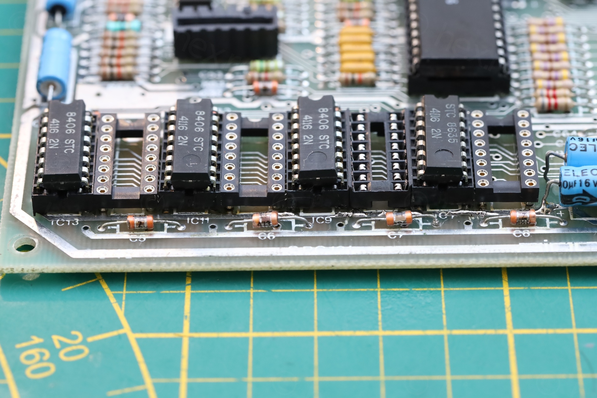
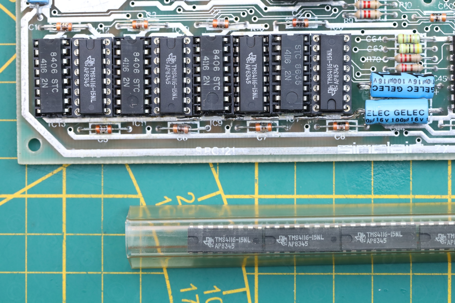
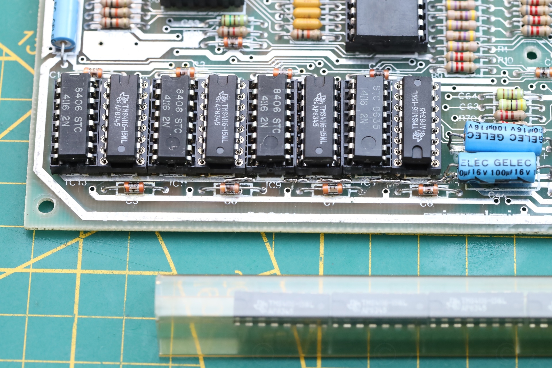
b) Most lower RAM chips installed in sockets – there were problems there:
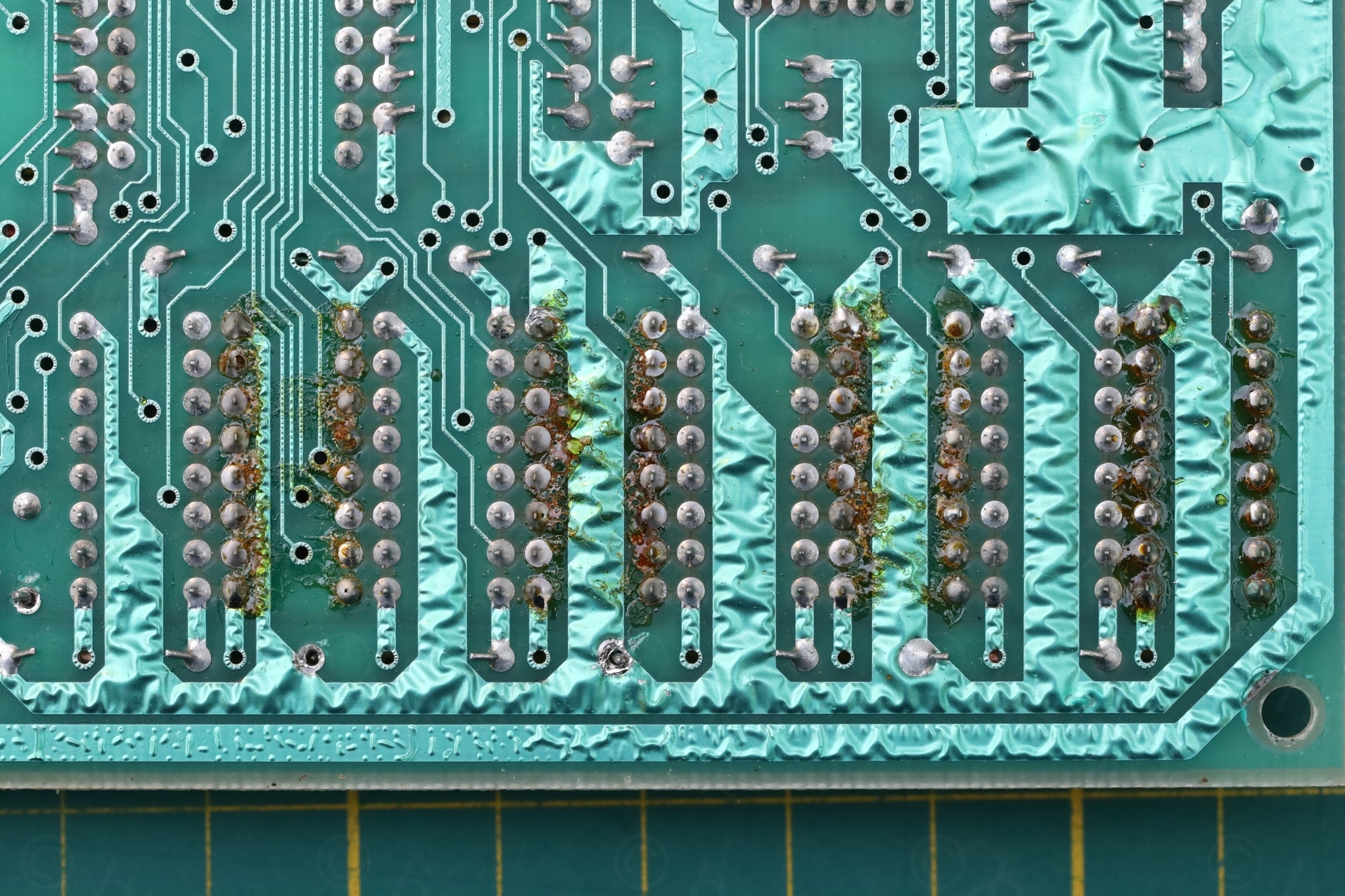
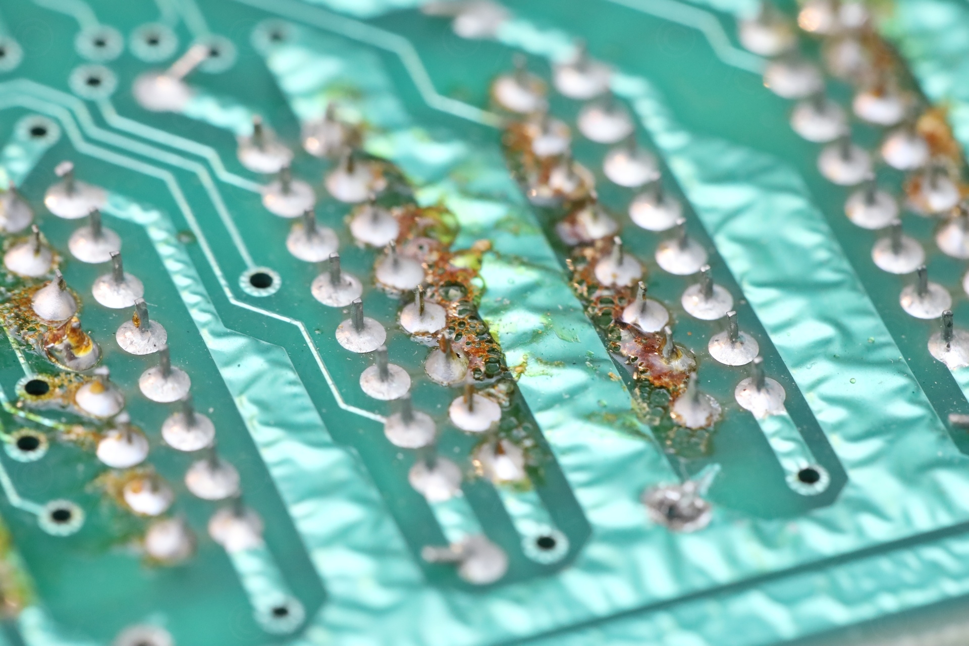
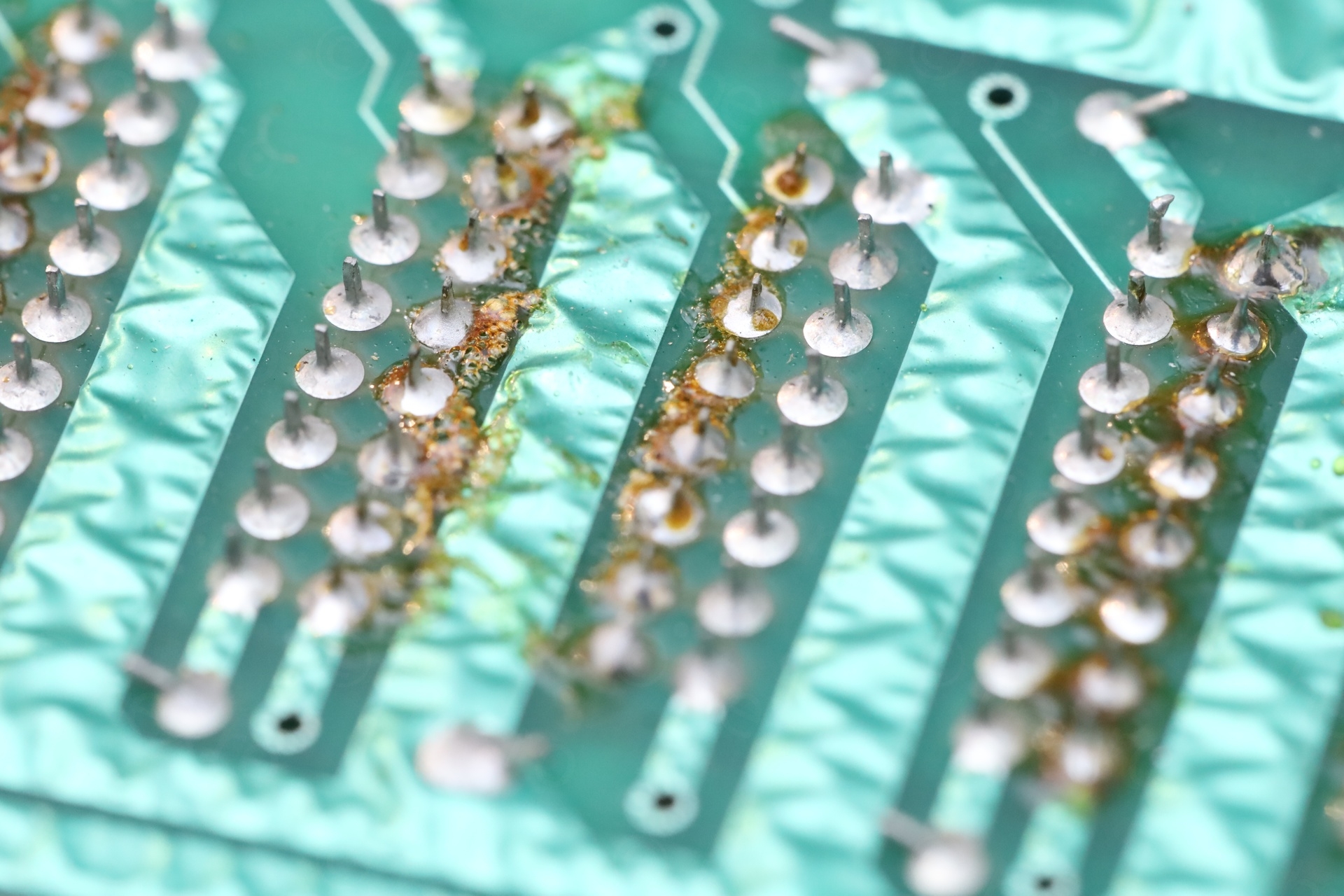
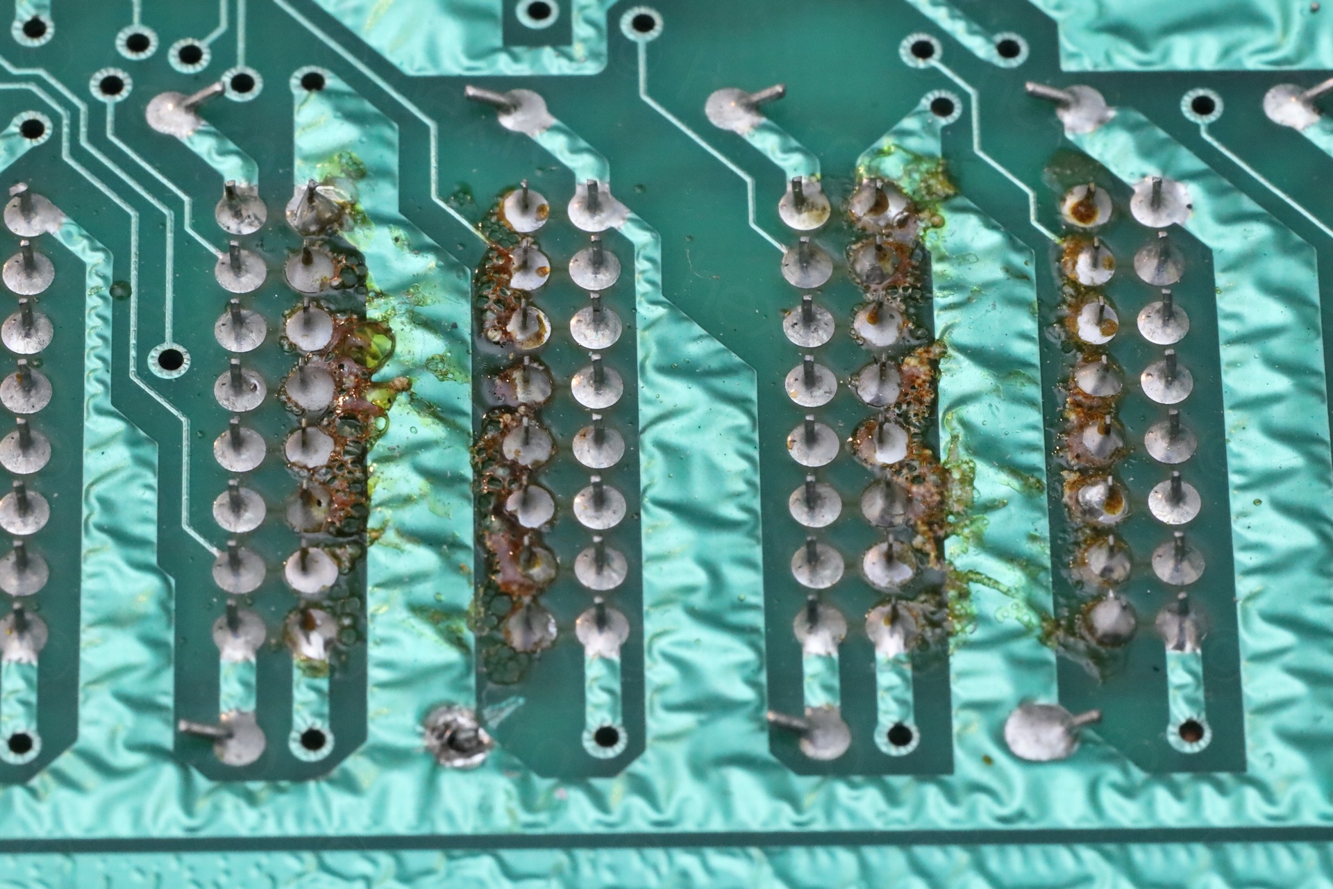
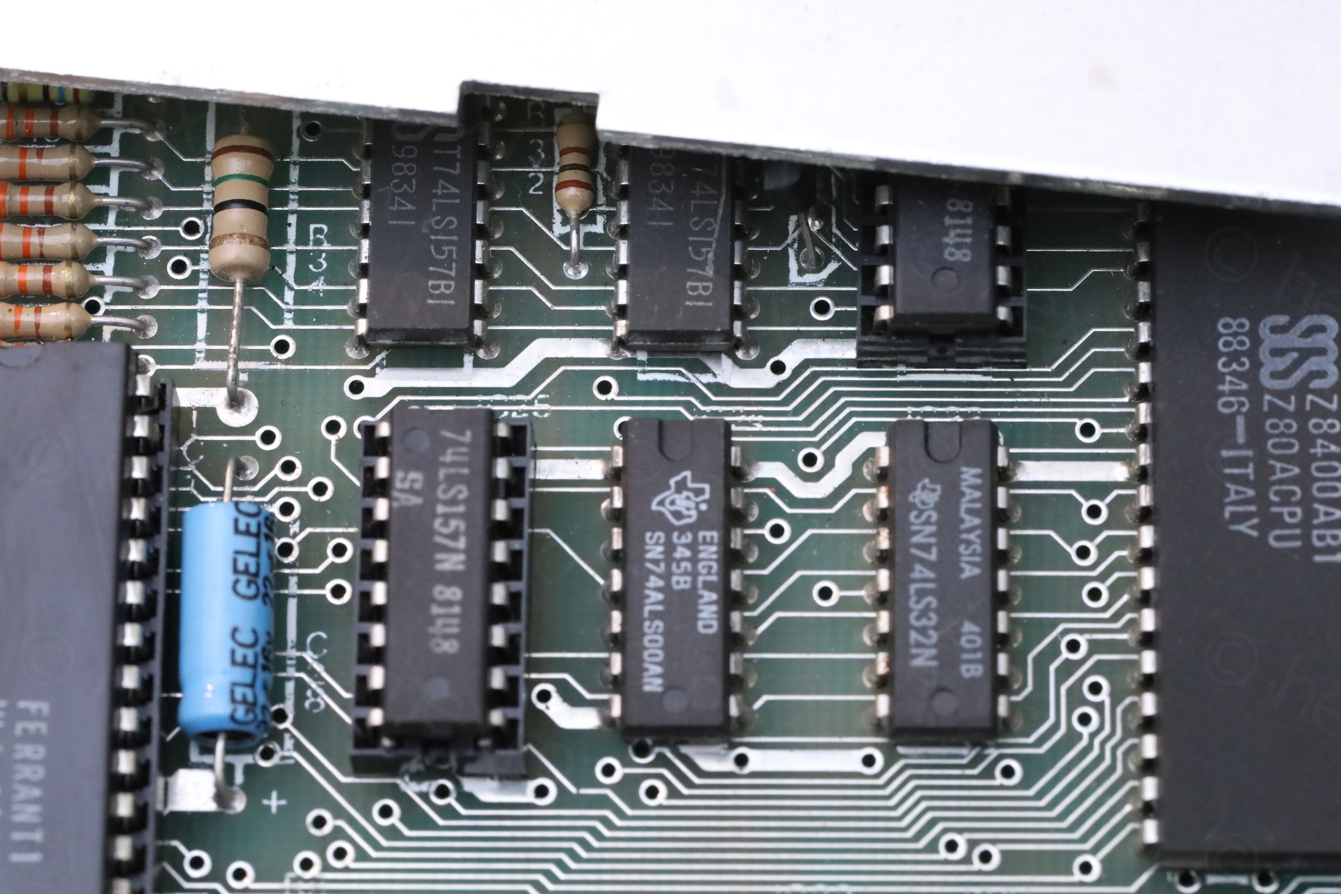
c) two addressable ICs were also installed in sockets:
On first power up – just the paper and the border but nothing else:
The current draw is 530mA, but …
a) a fat capacitor gets warm – not good
b) one of the addressable chips is getting also warm
The 12V line is 3.01V.
The -5V line is oscillating between -4.17V and -4.23V.
The 5V line is 4.99V.
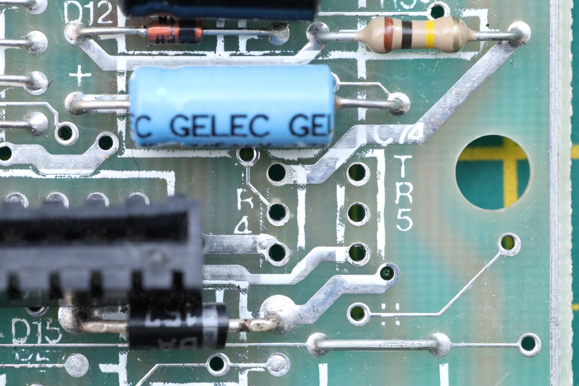
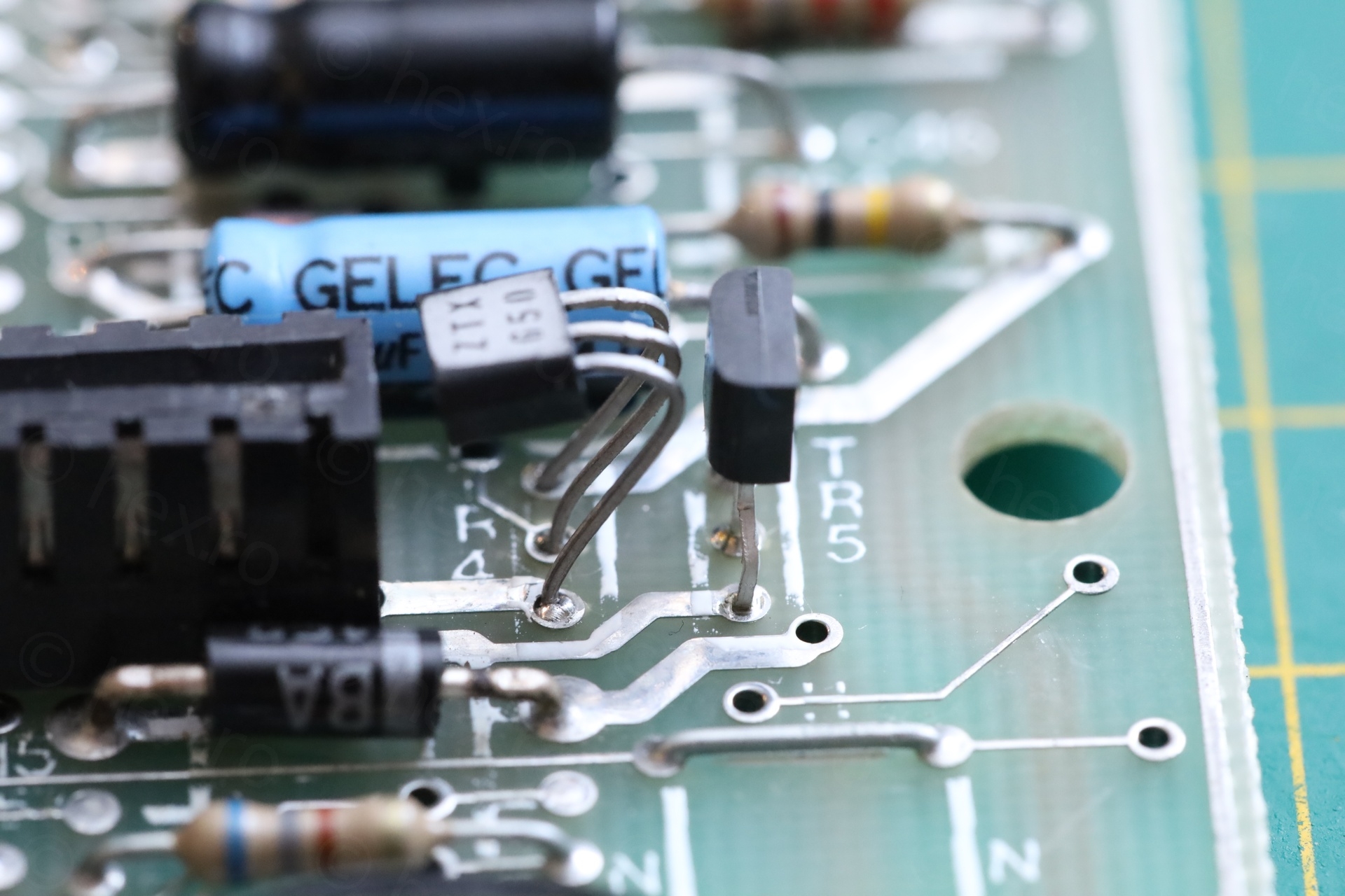
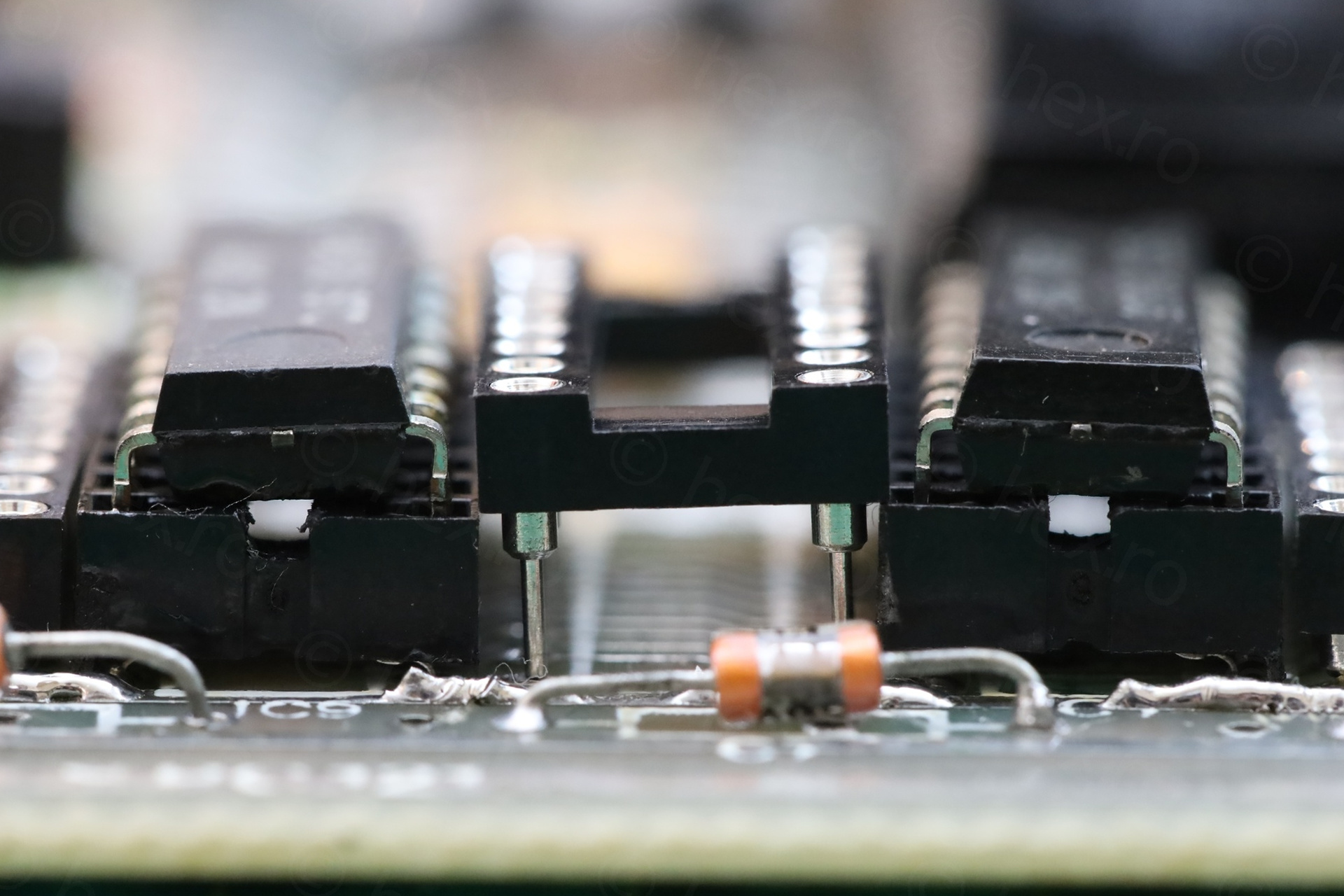
I suspect BC327 is installed incorrectly in TR5 position, because original ZTX transistors have to face each-other, but if you use a BC replacement, the BC has to be faced backwards due to different pin-outs.
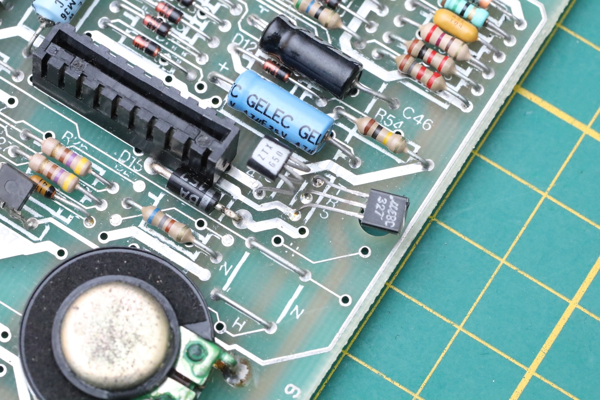
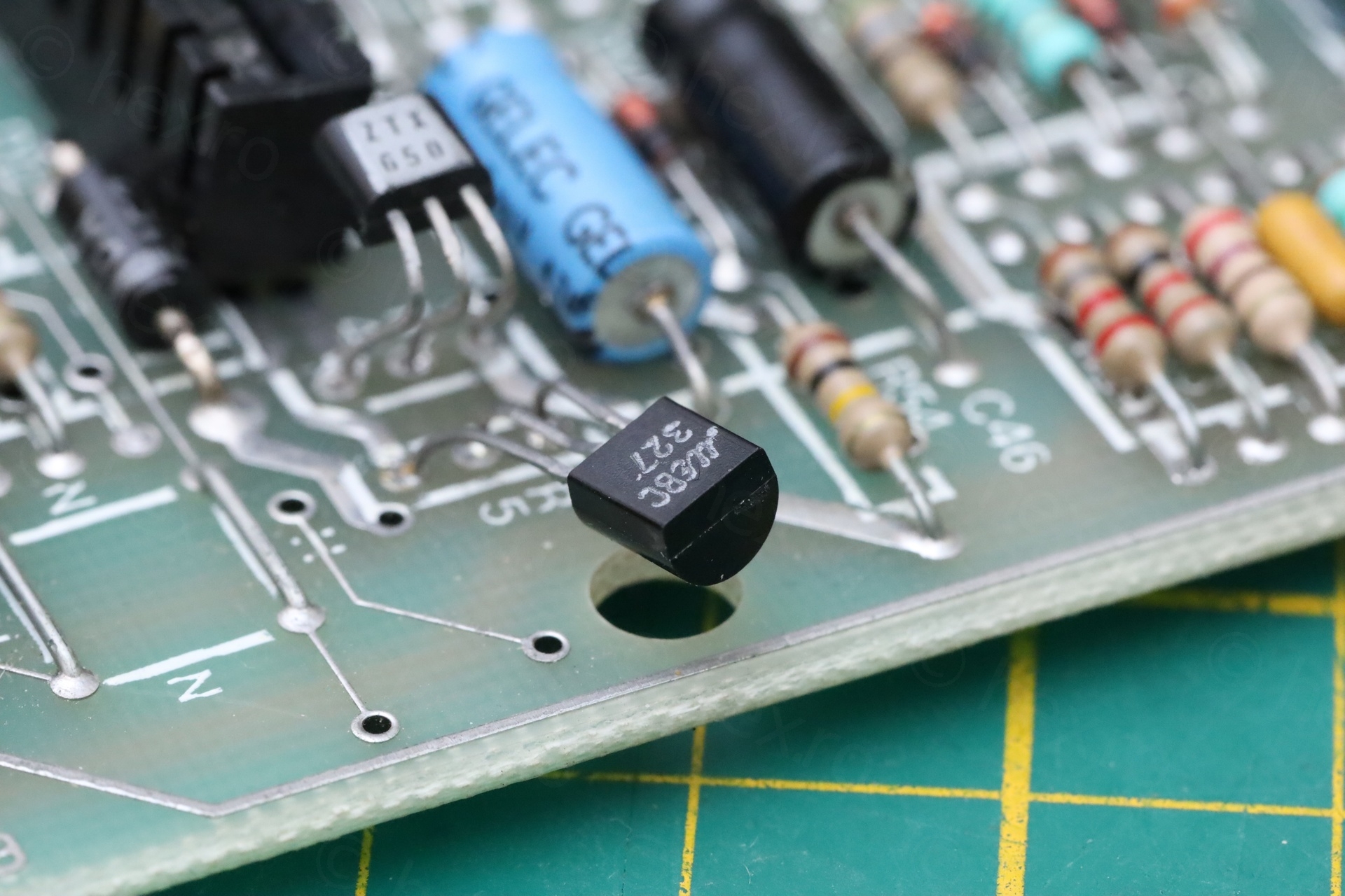
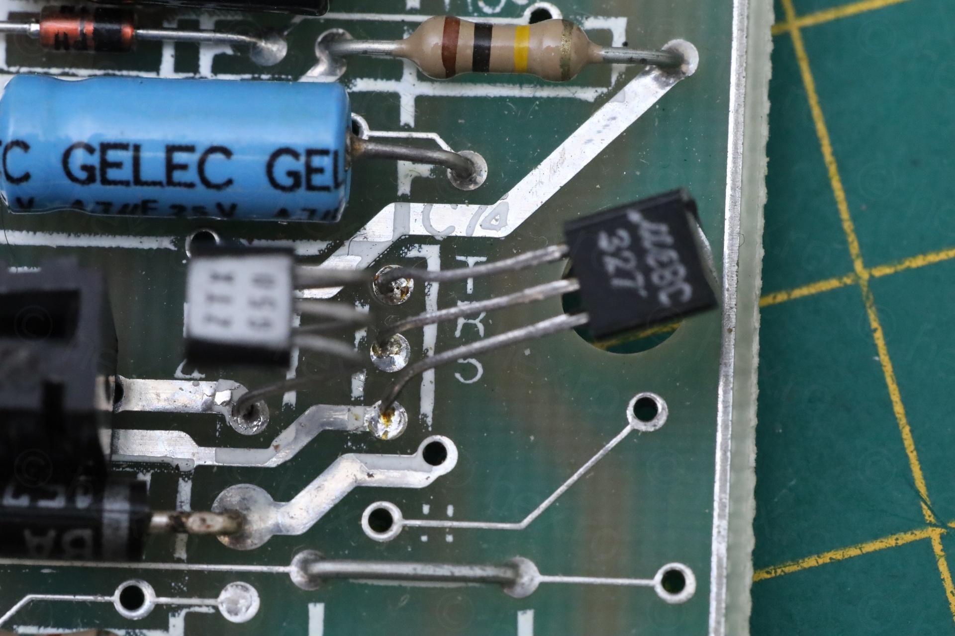
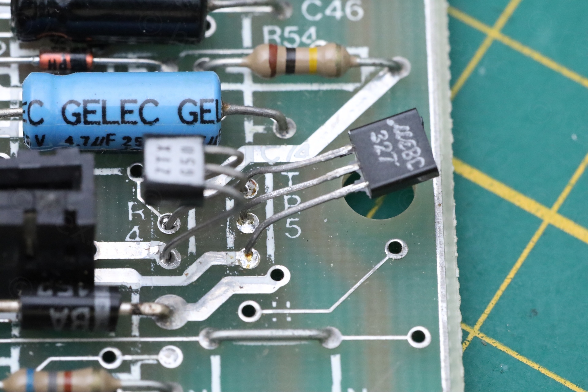
The top pin (on the motherboard) of TR5 is the Collector.
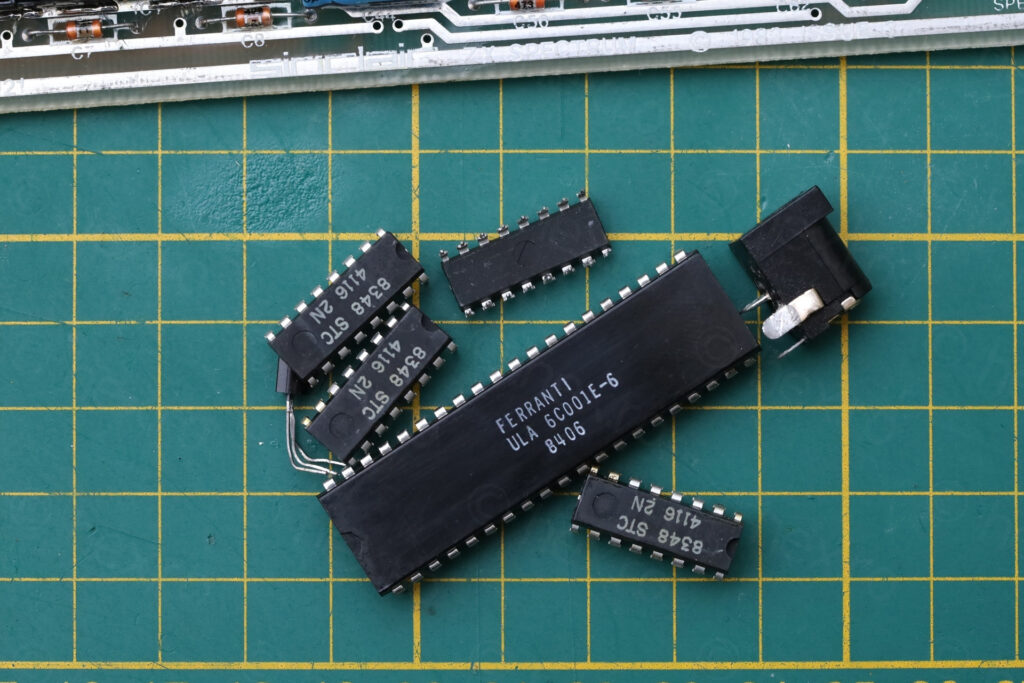
I proceeded to de-solder both transistors. TR4 tests good, so I will reuse it:
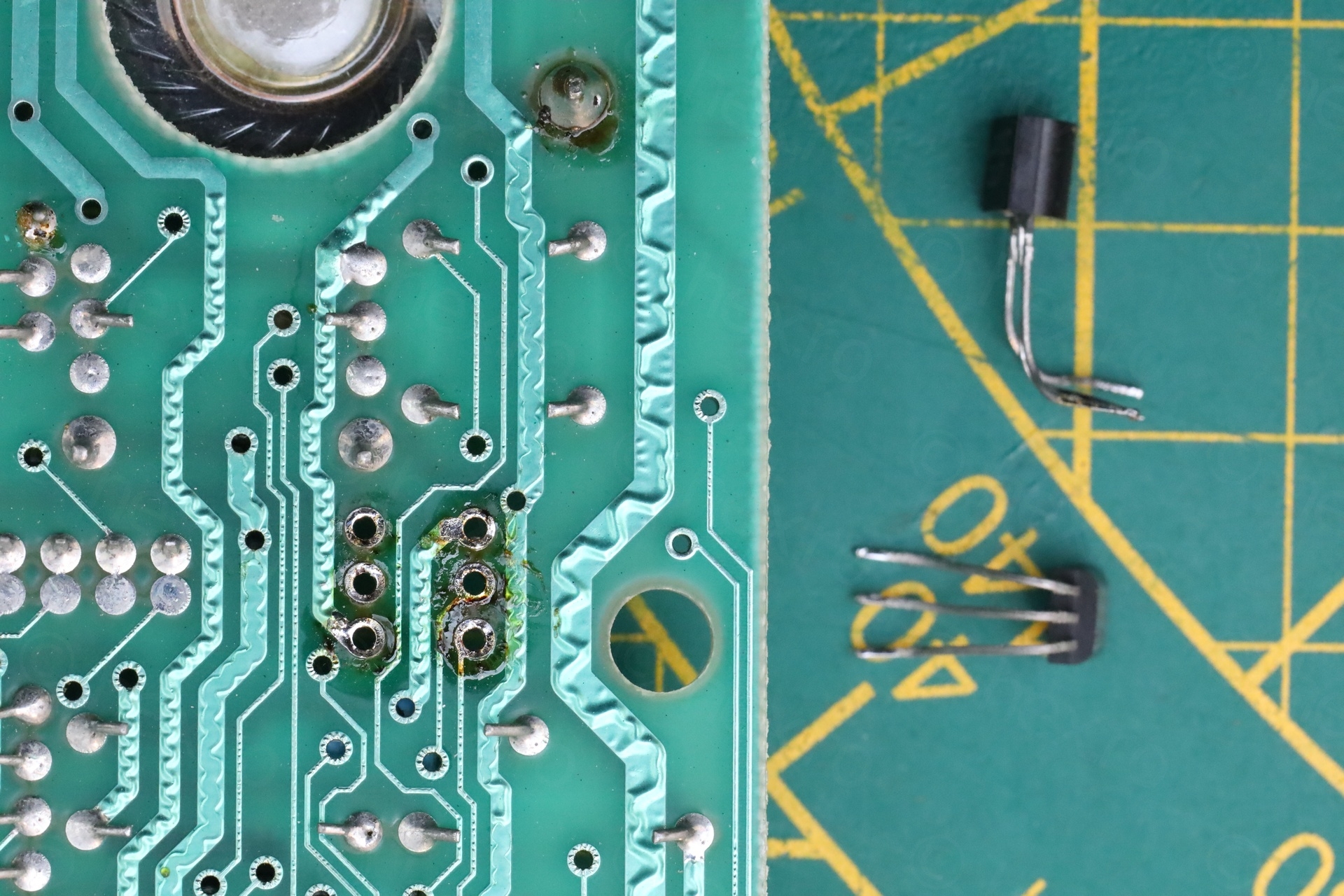
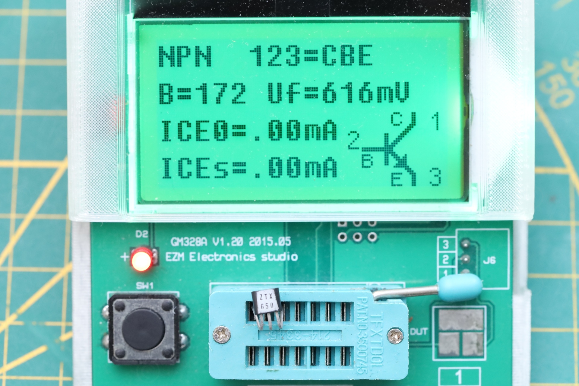
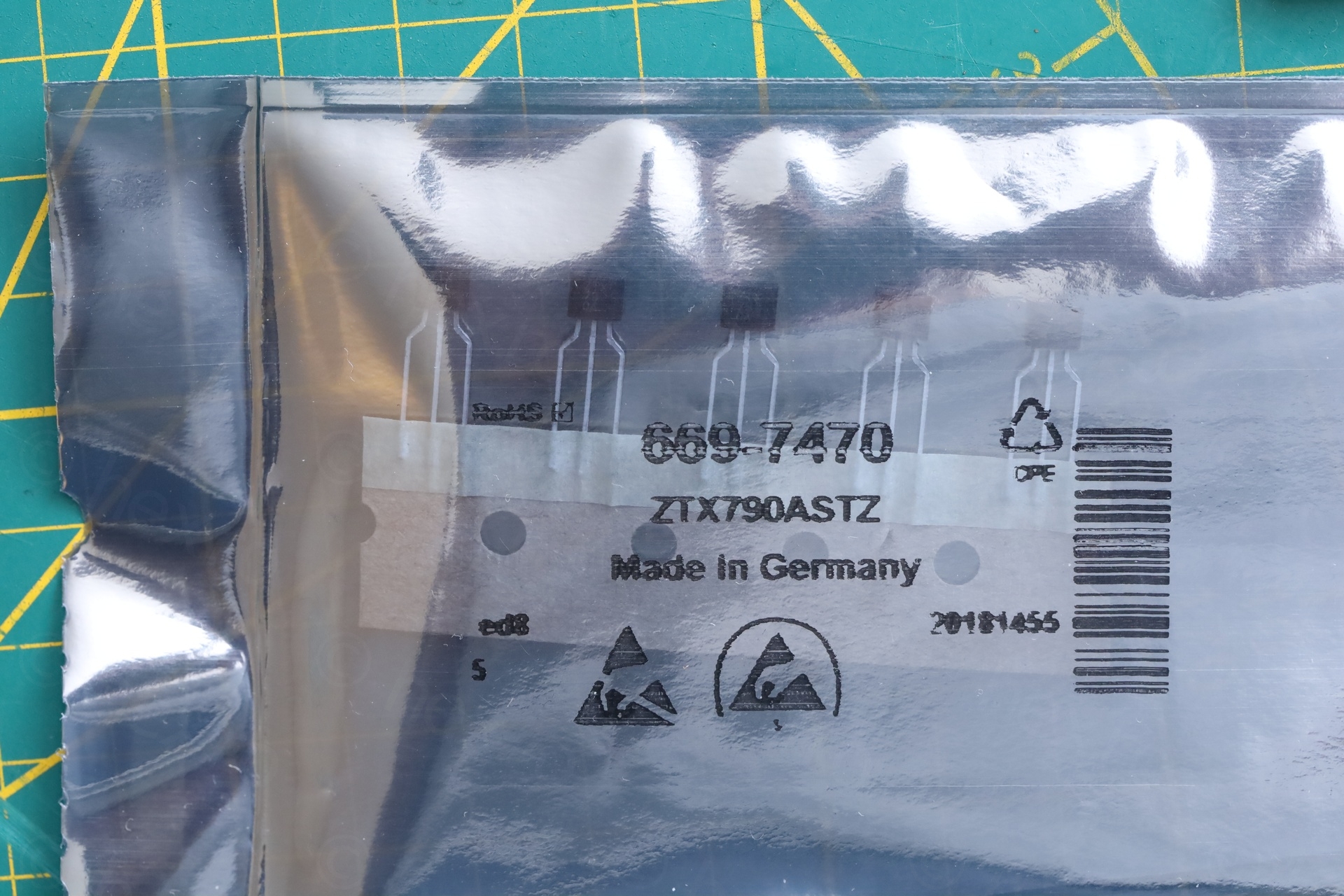
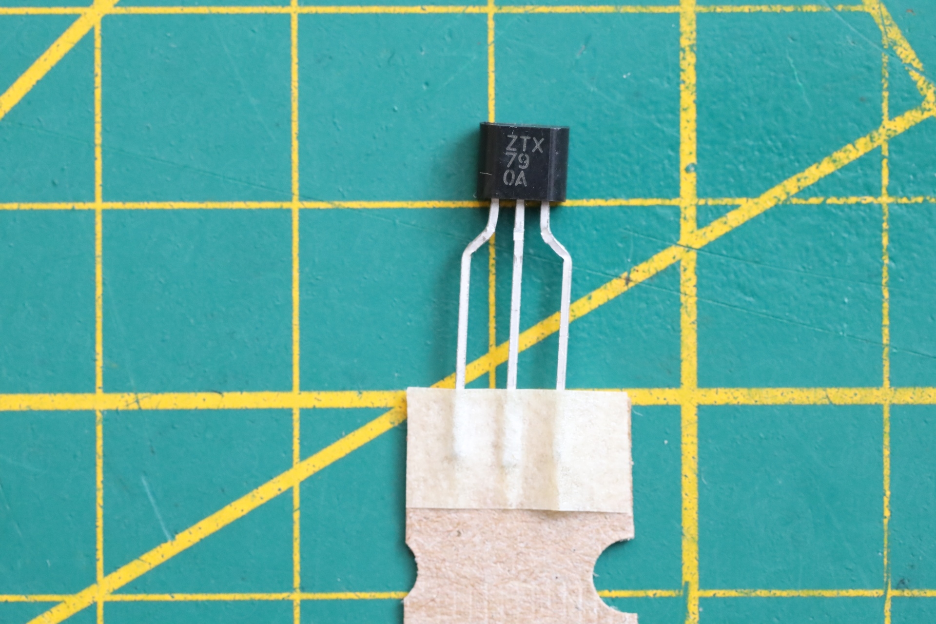
For TR5 (ZTX213 – PNP, VCE -30V / -200mA / 0.5W / 200MHz) I will use ZTX790ASTZ (PNP, VCE -40V, -2A, 1.5W, 100MHz). The BC327 also tested fine, but I like the look of the motherboard when both transistors are ZTX.
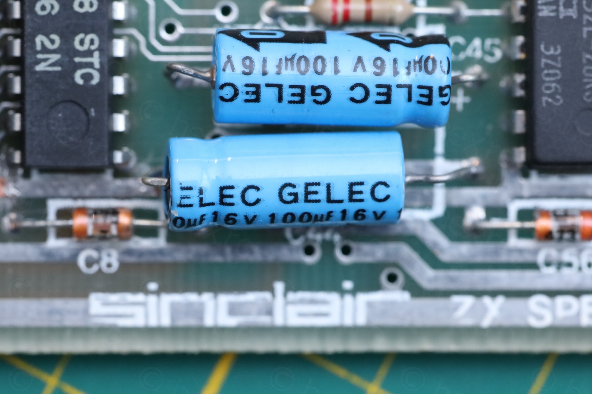
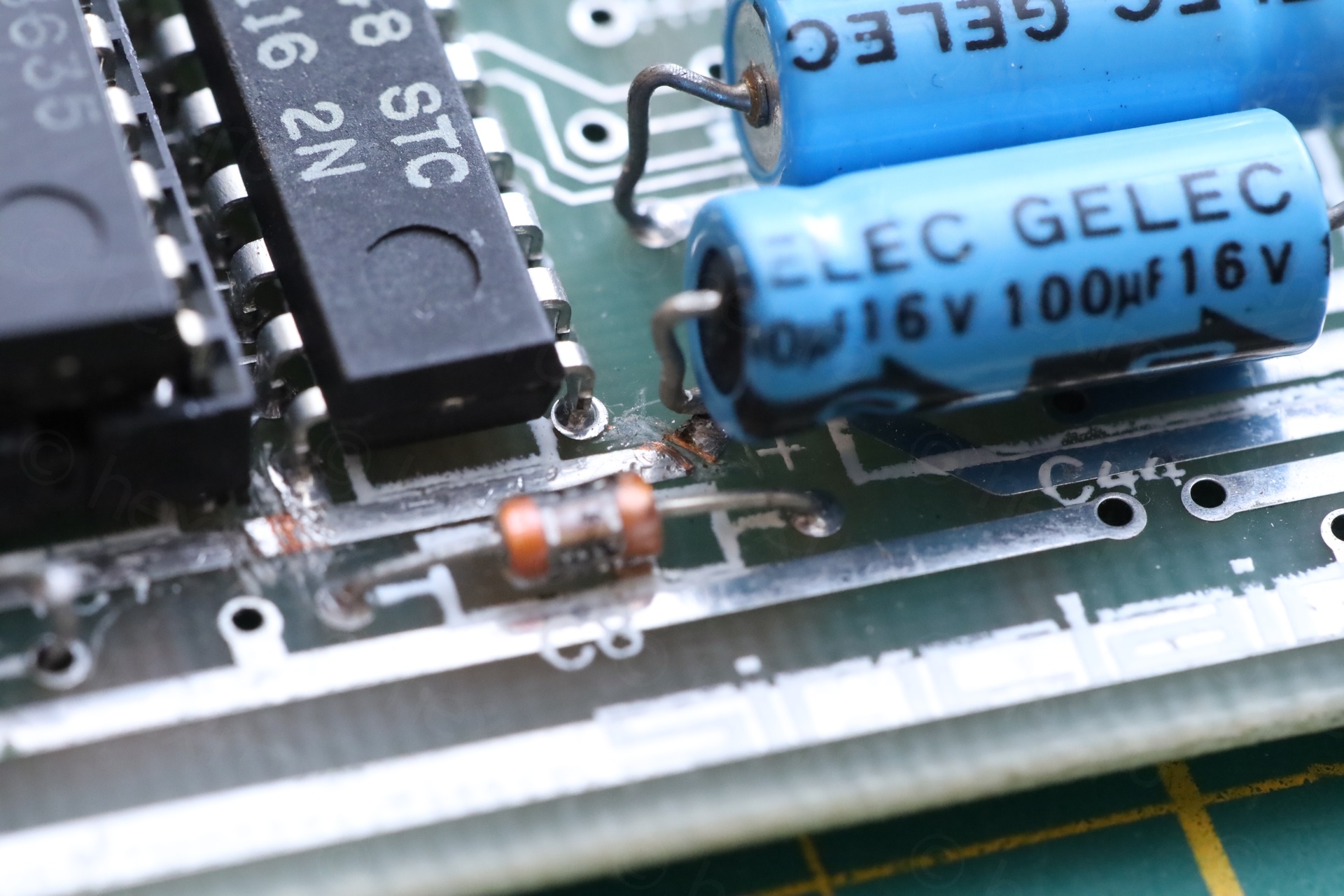
I tried to rearrange a bit the capacitors, as due to shipping (or storage), they were leaning to one side) and I found C44 was left de-soldered on the + side. Pffff
After putting in a proper ZTX790ASTZ transistor and re-soldering TR4 (ZTX650 which tested good) and reconnected the unsoldered C44 -> results are just marginal:
The 12V line is 0.0V
The -5V line is -4.01V (but stable)
The 5V line is 4.99V
While checking why I don’t have 12V on the lower RAM ICs, I went to see the voltages on the LM1889 since that one is also supposed to have 12V, and, to my surprise, it has 12V. It makes sense, there was an gray image appearing. Hmmmm.
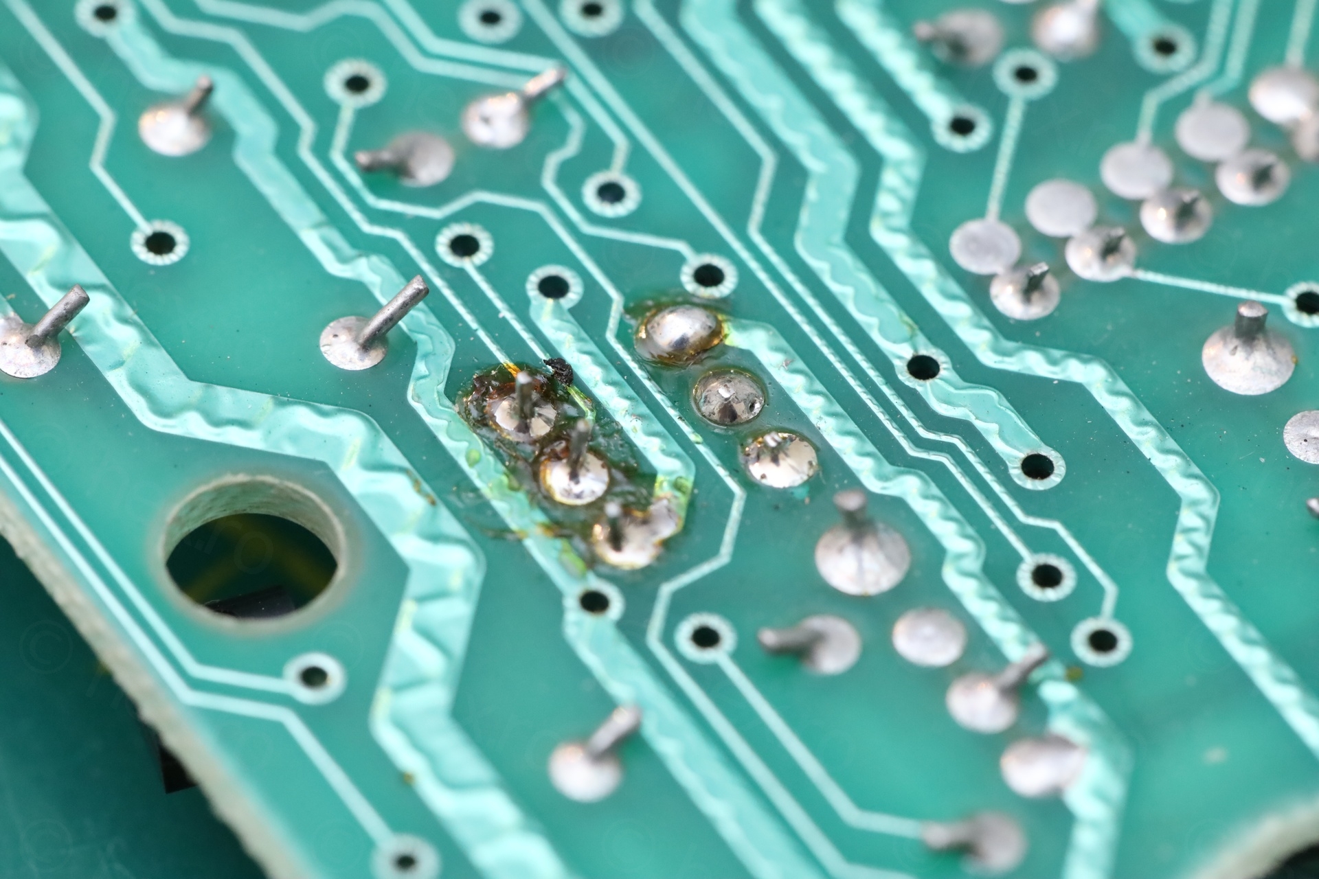
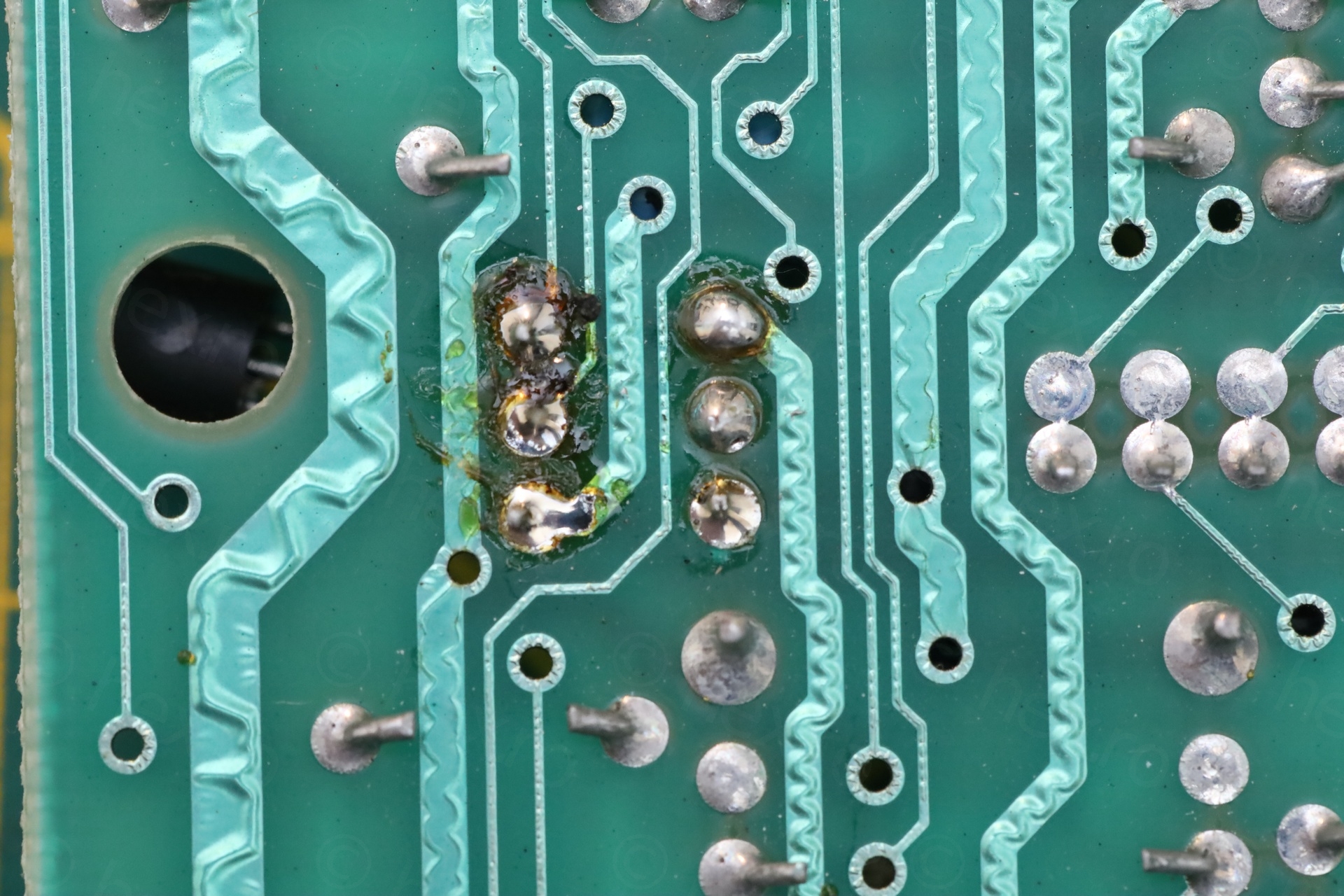
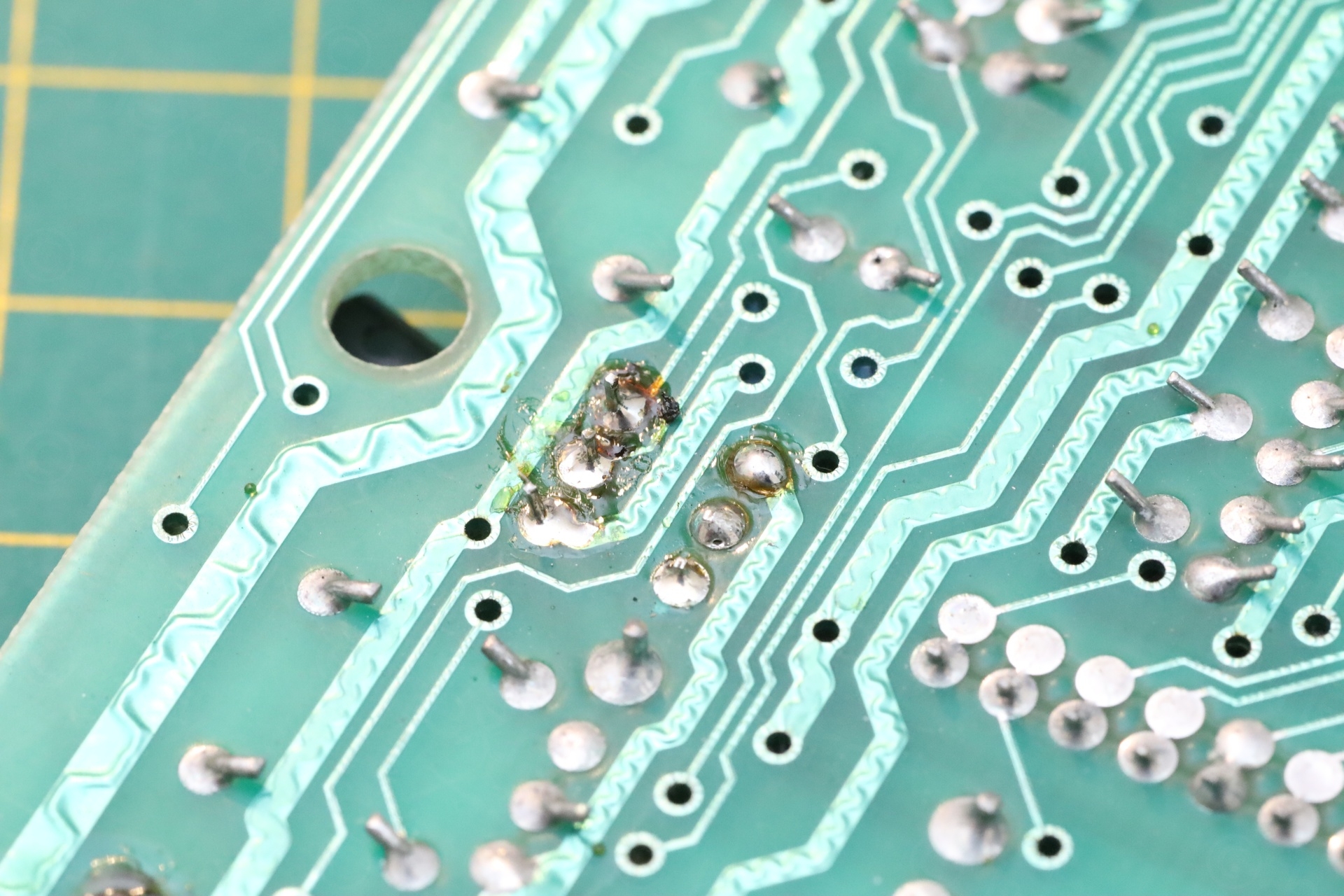
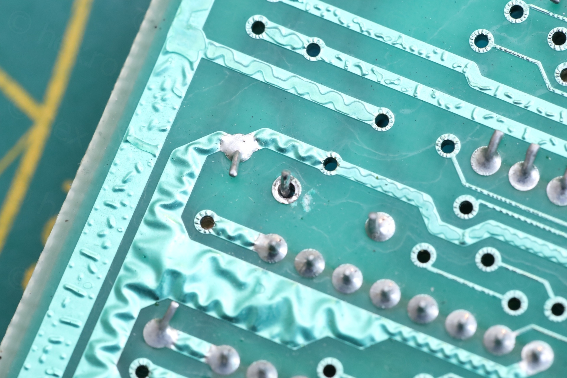
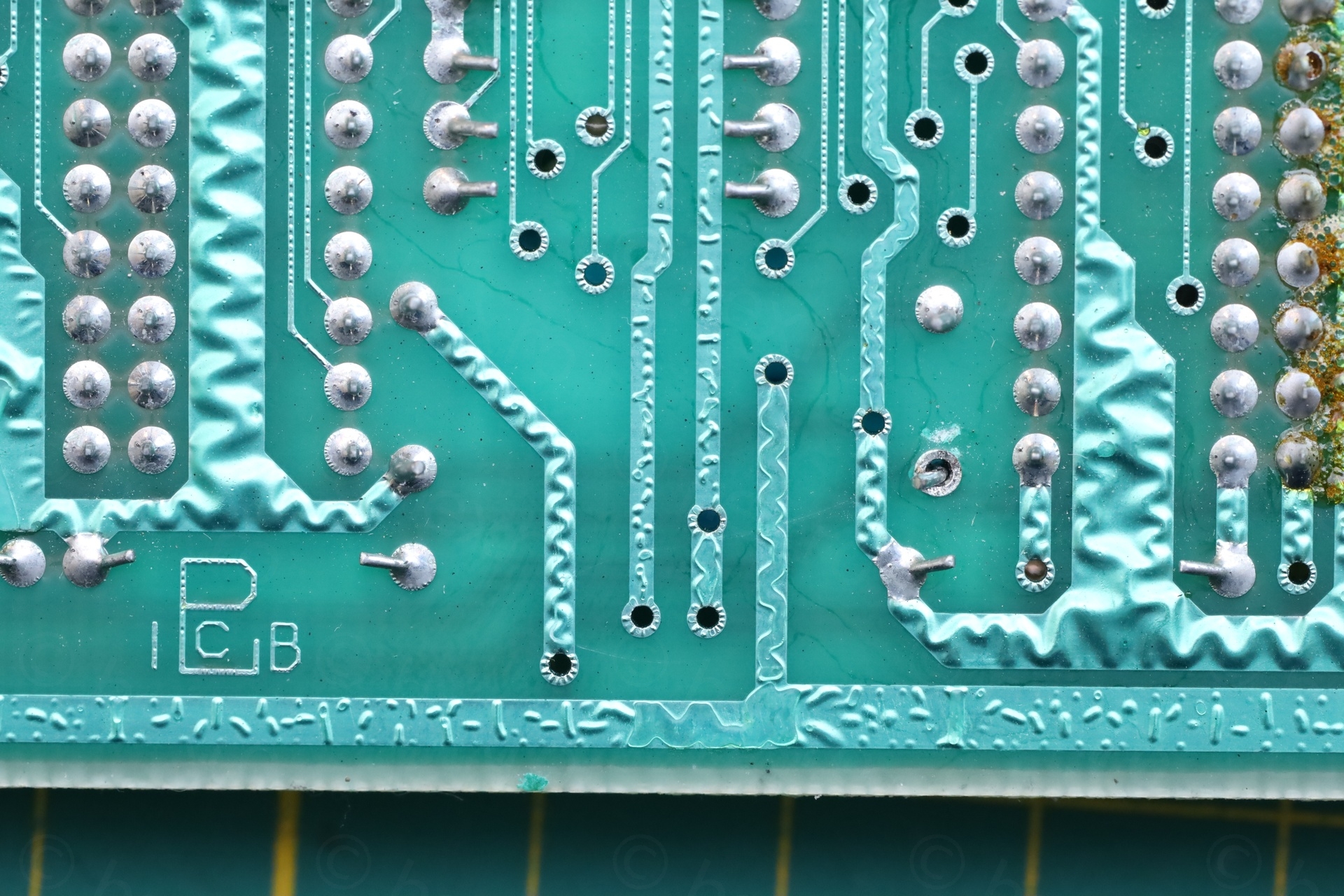
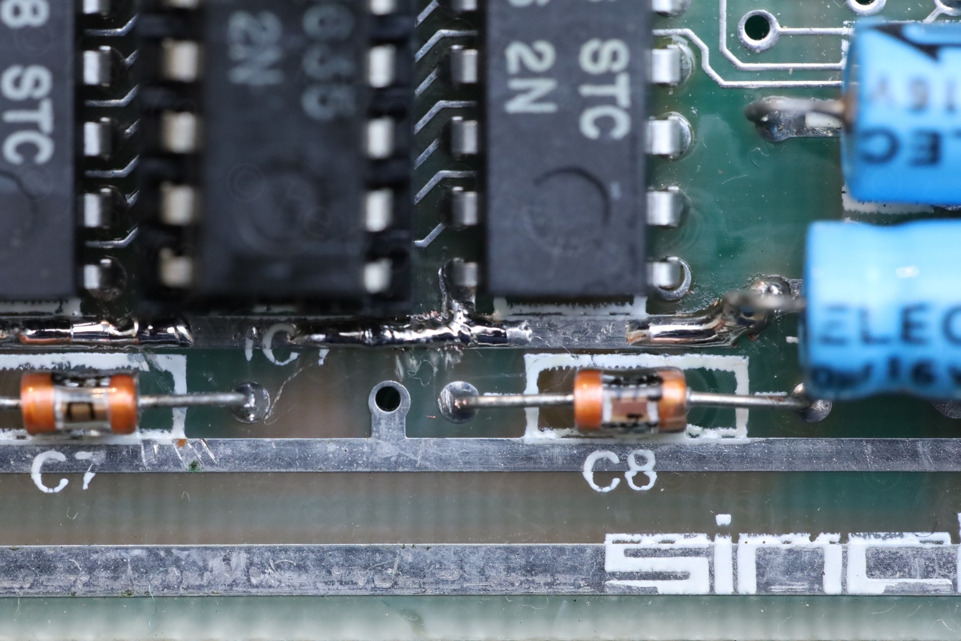
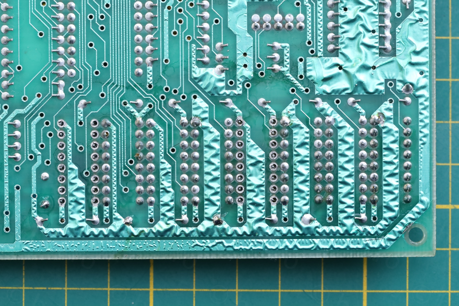
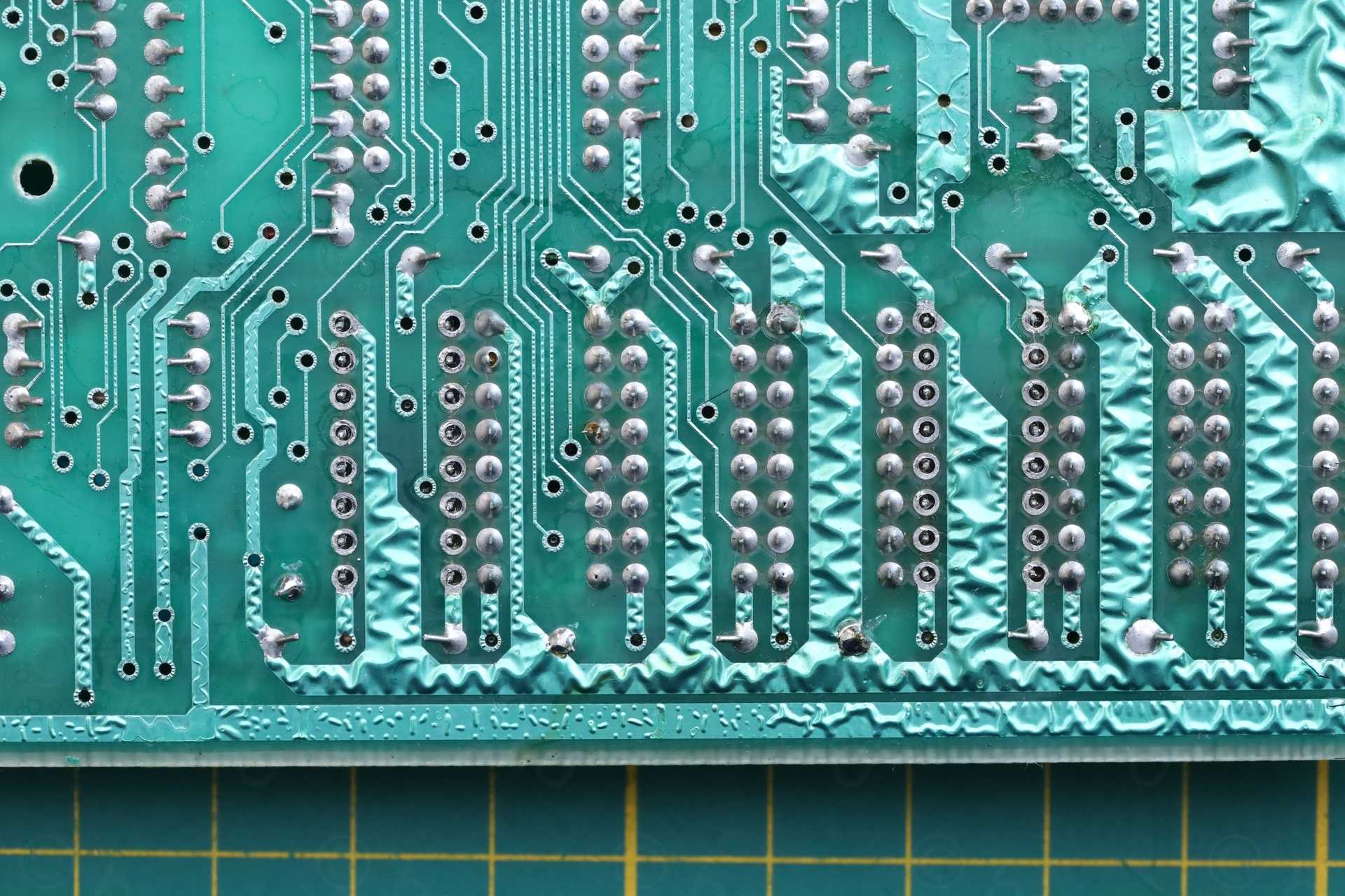
I then spotted the horror. The 12V trace going to the lower ram chip is scratched in two places – that’s why the lower ram was cold after boot. And that’s why I wasn’t seeing the 12V when I was measuring them.
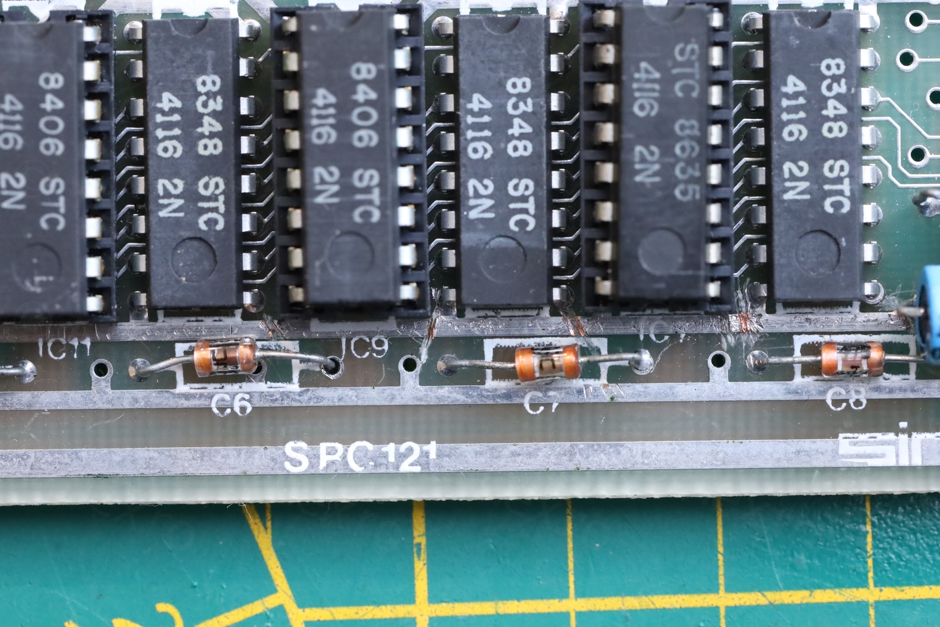
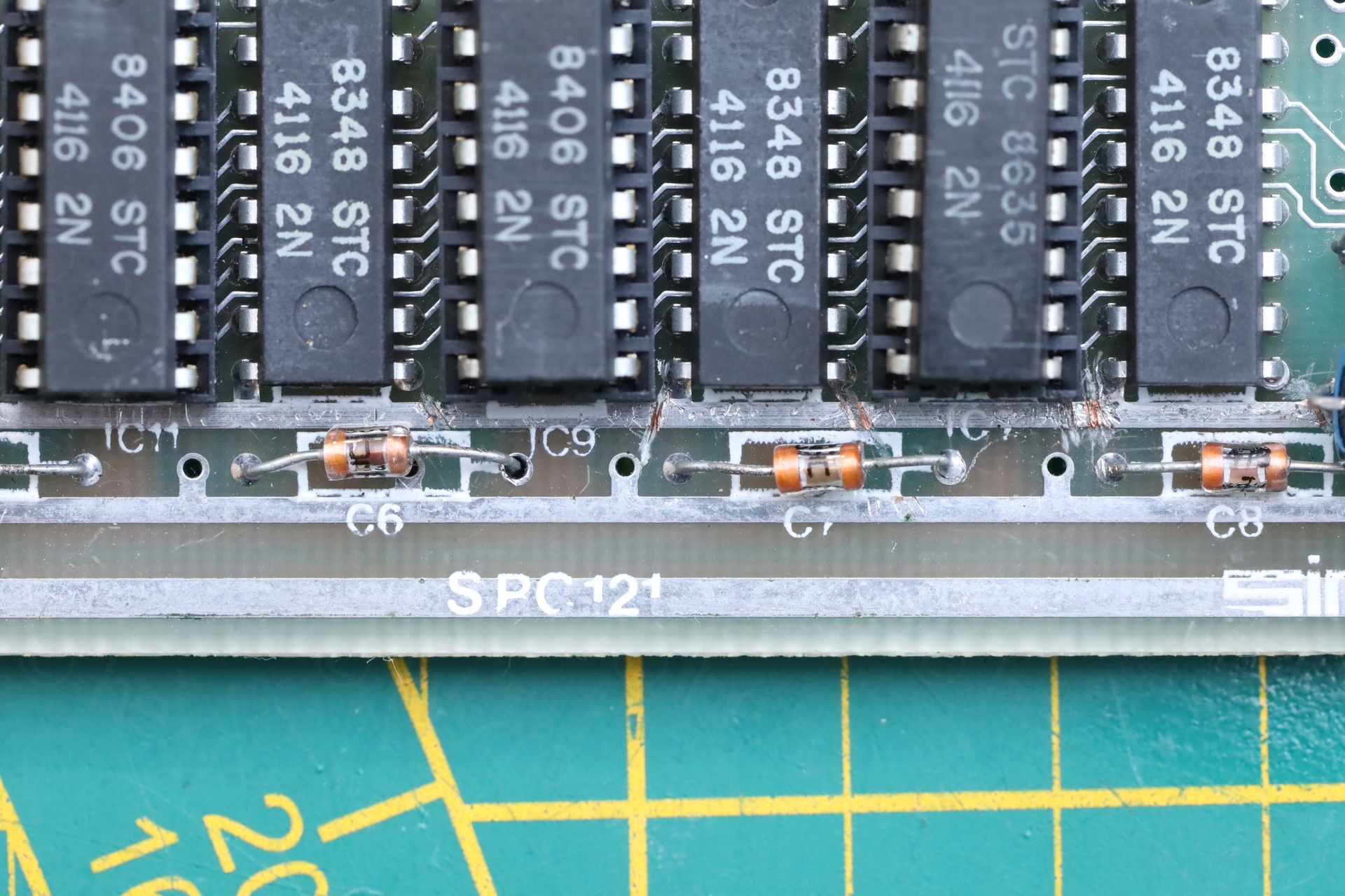
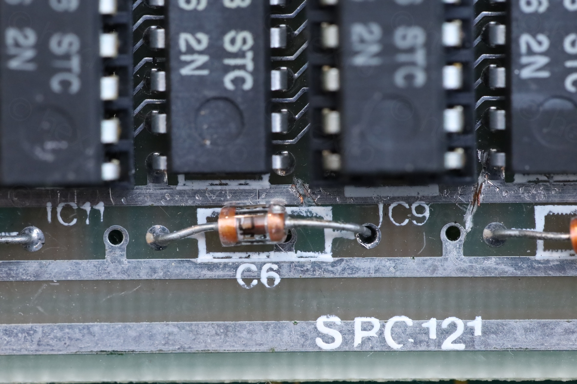
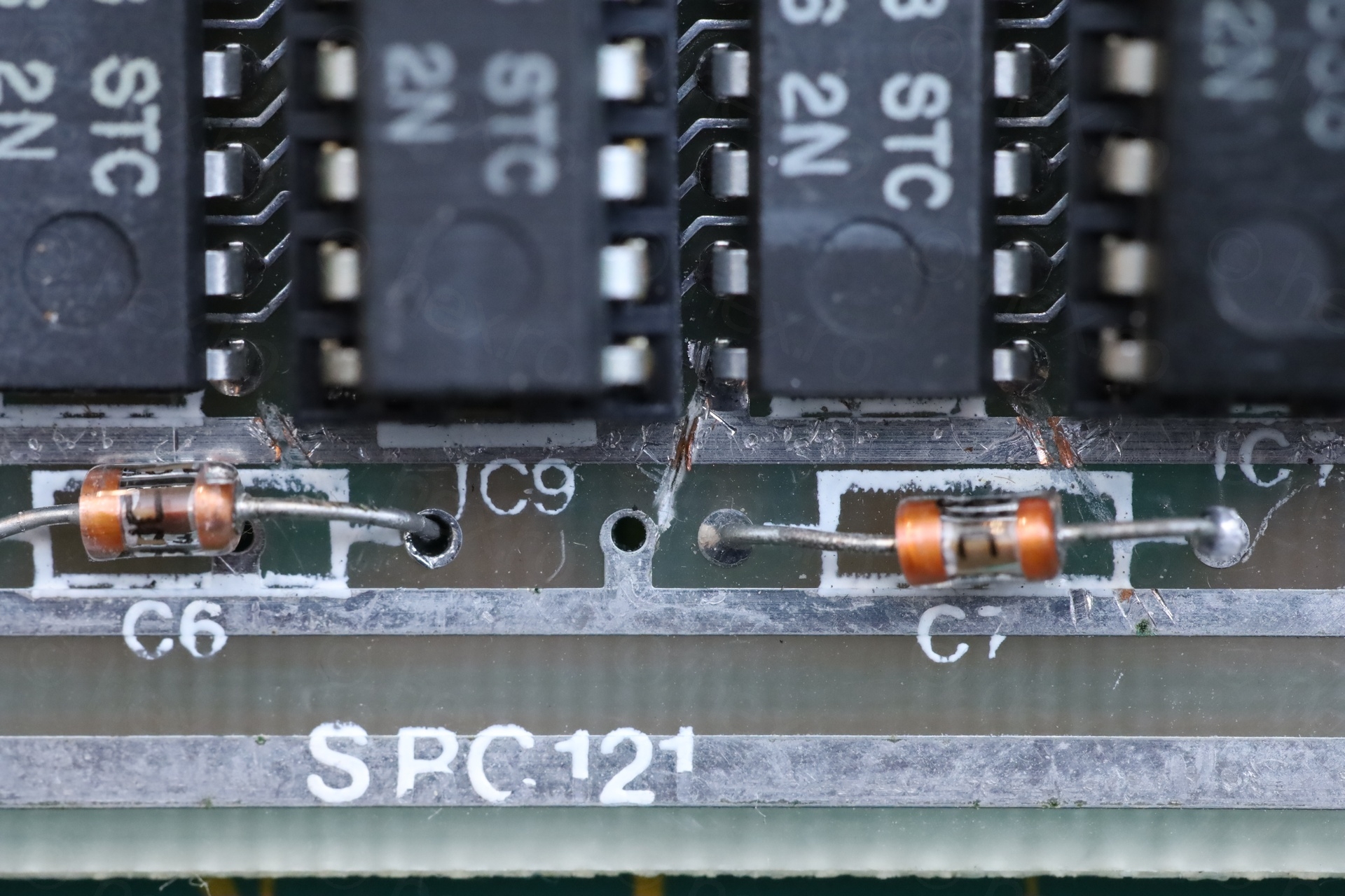
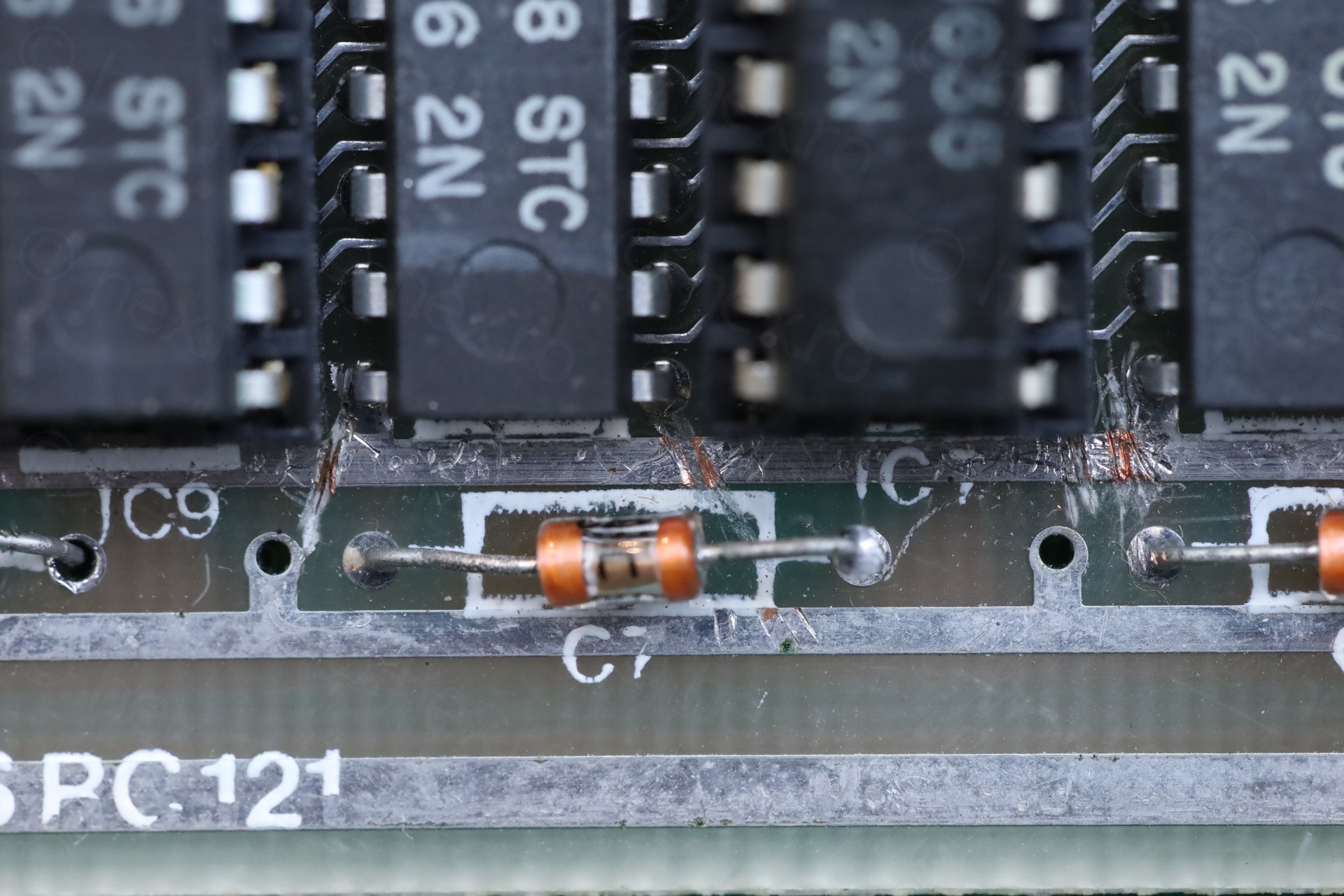
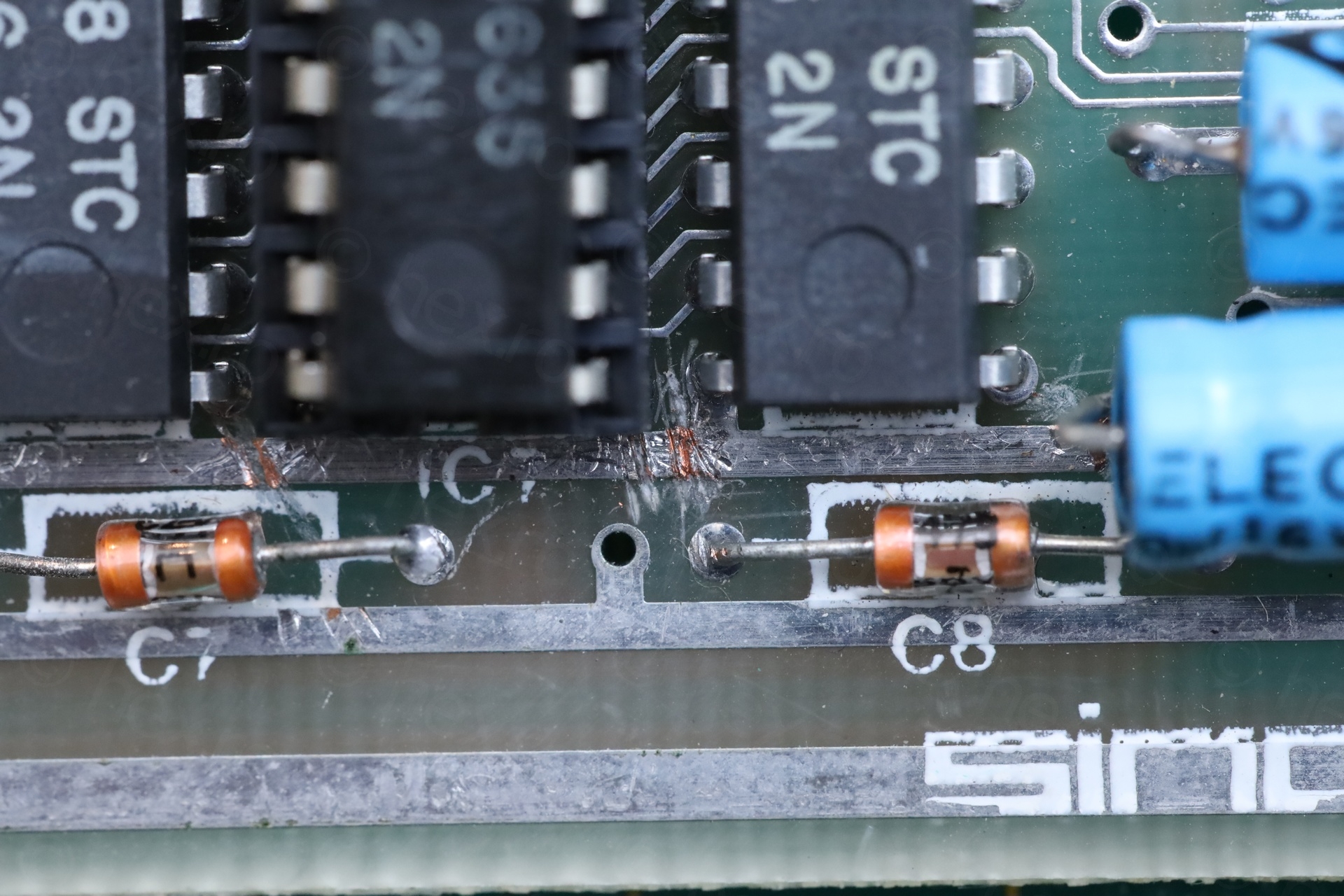
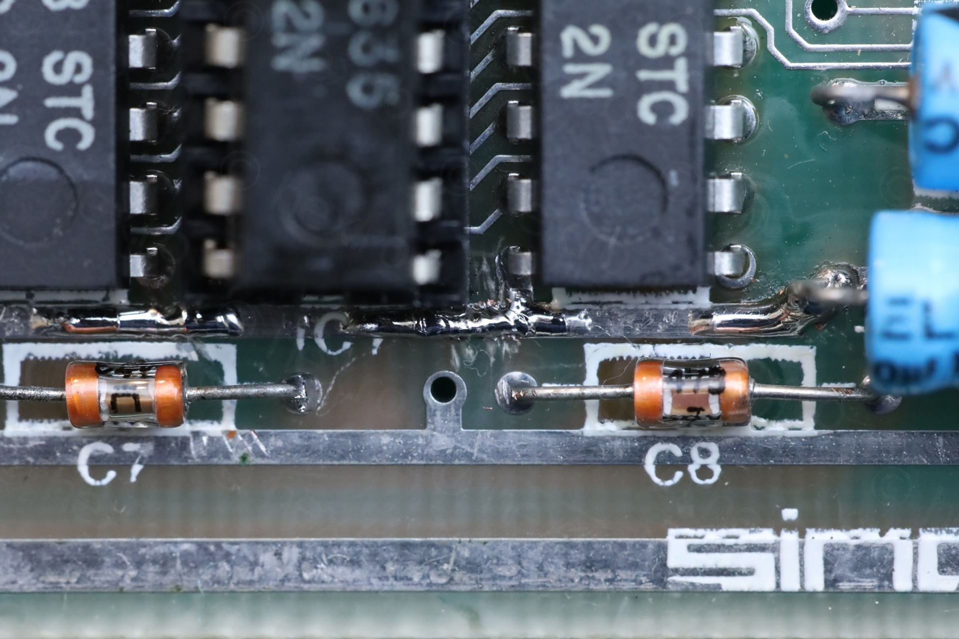
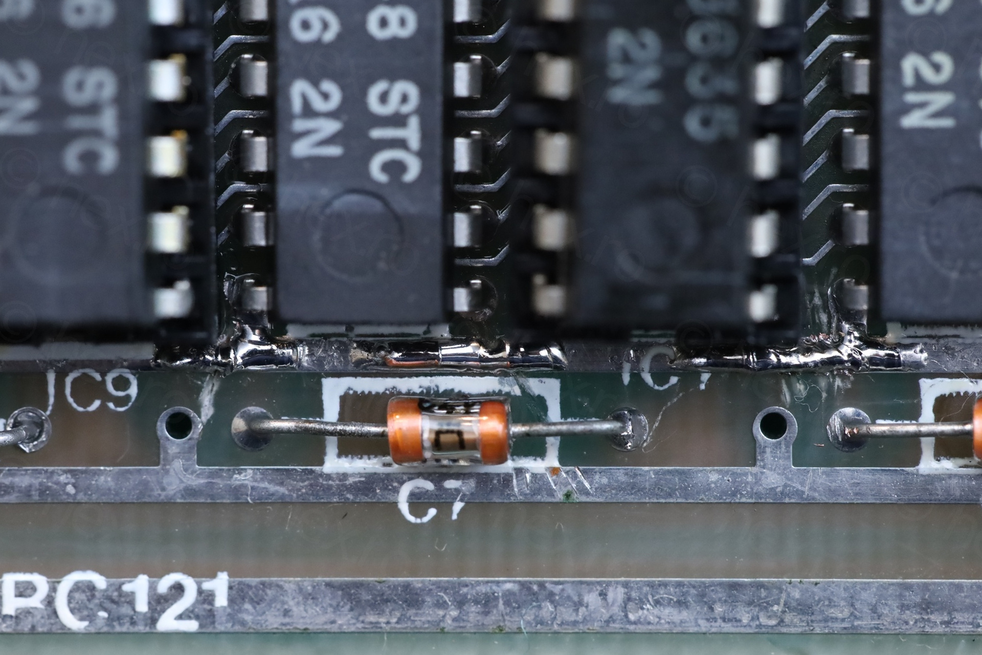
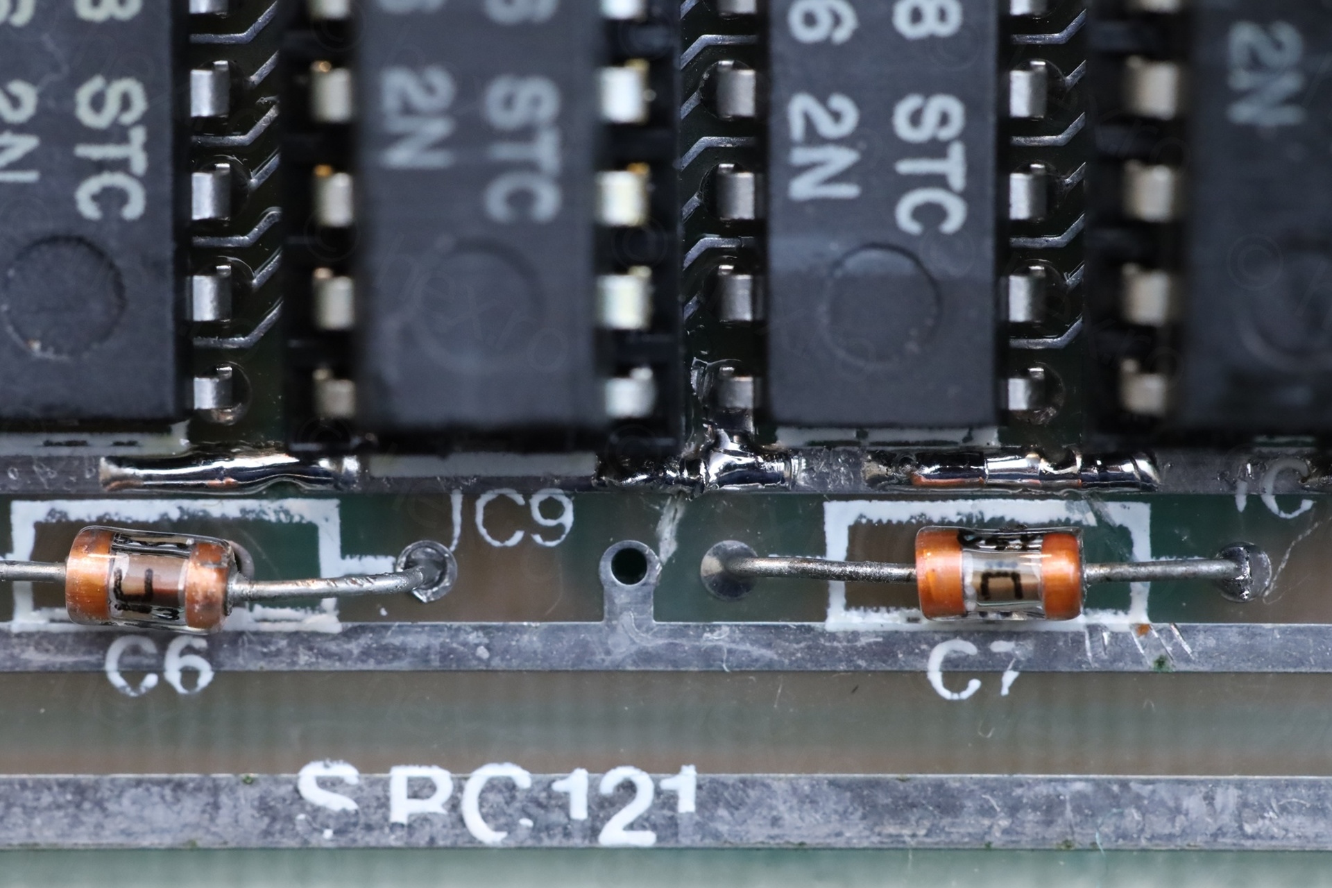
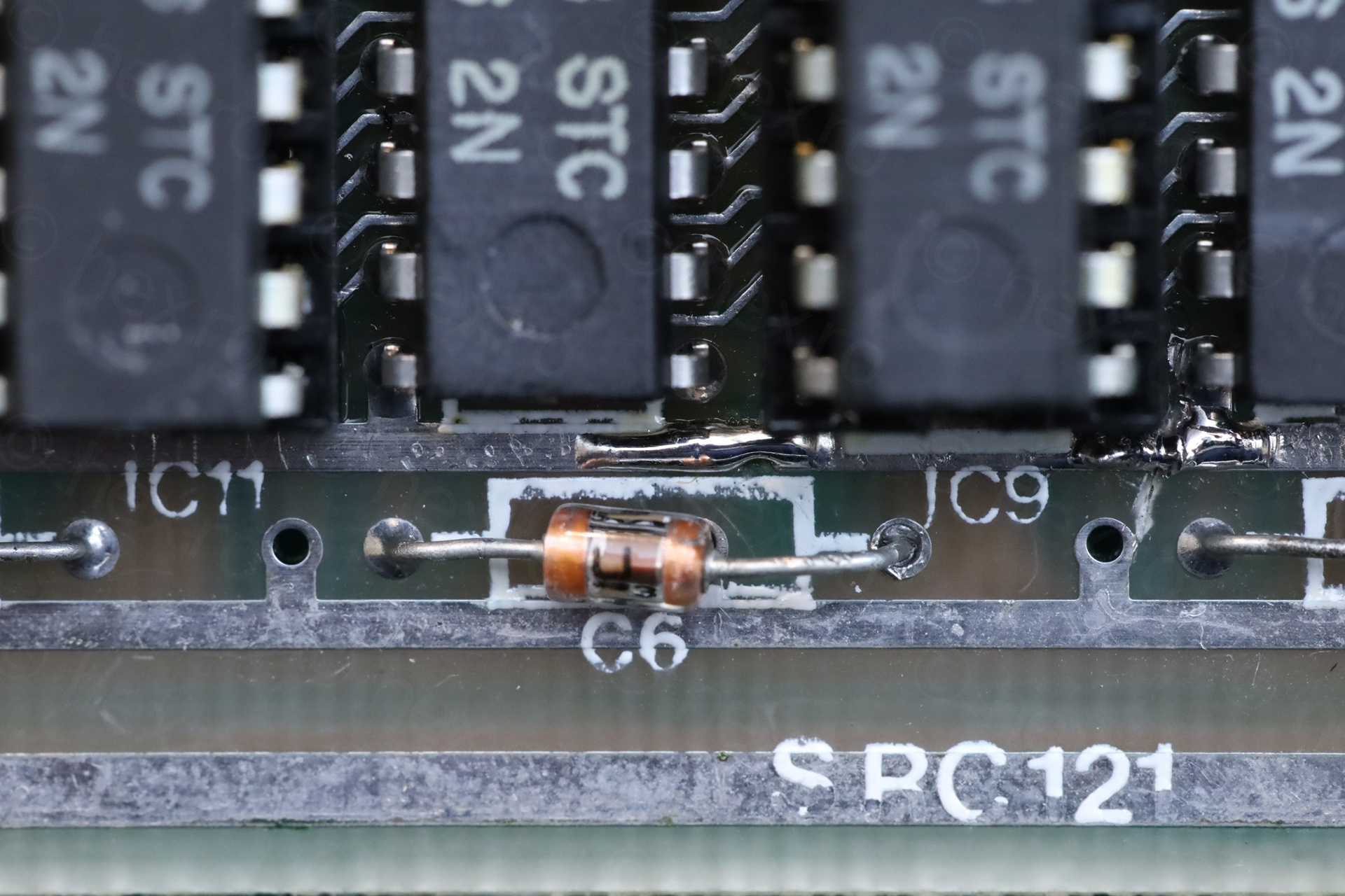
I also spotted C6 and C7 de-soldered, in the vicinity of the 12V line. The seller really try to chase the 12V and why it is low.
There are also 12V on the positive line of C44 now that is soldered properly.
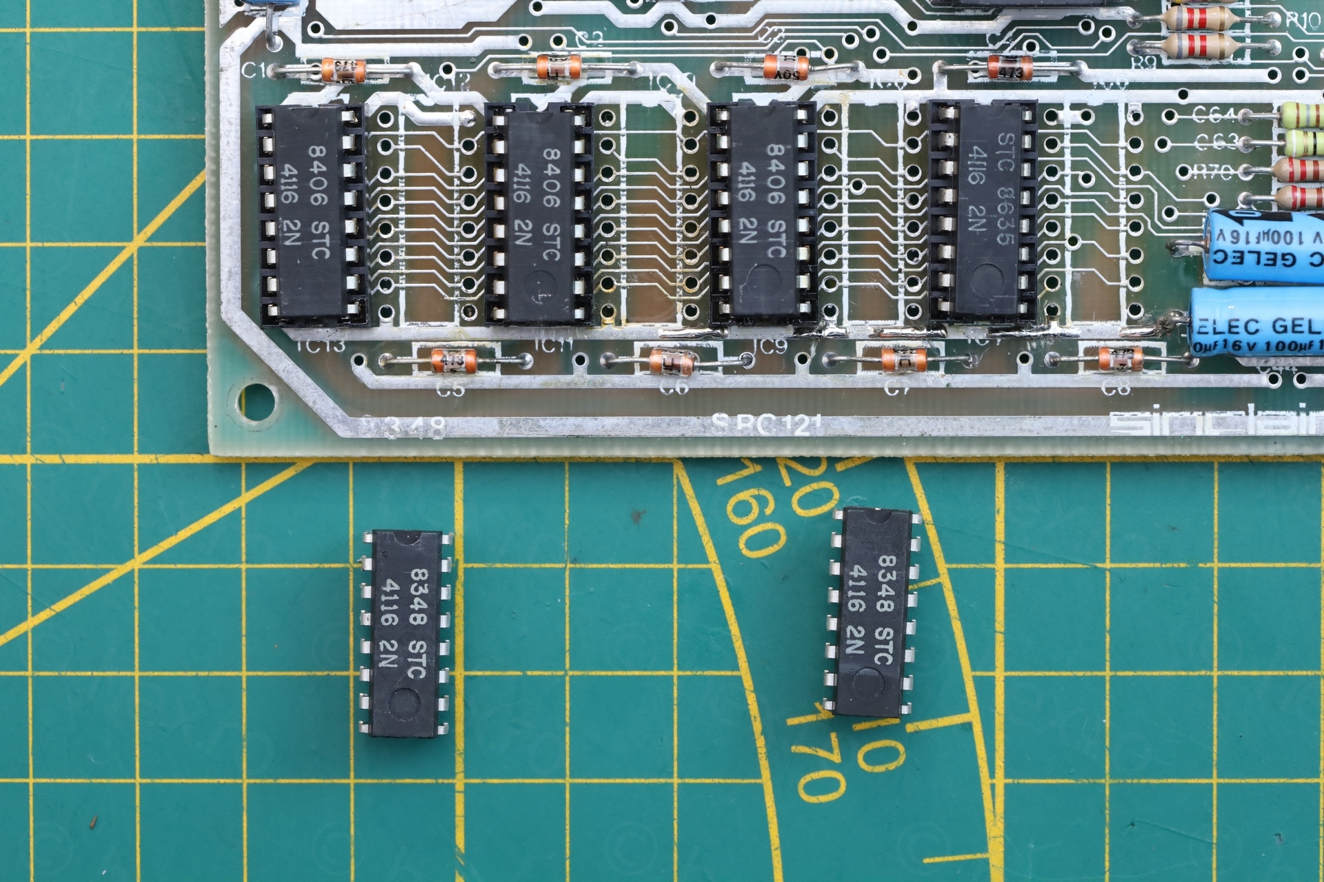
After bridging the 4 gaps – results are not good. There is indeed a short to ground, the power supply stopped at 1.5A to prevent more damage. IC6 and IC10 get hot on the infrared camera, but unfortunately, they are soldered so they need to be de-soldered.
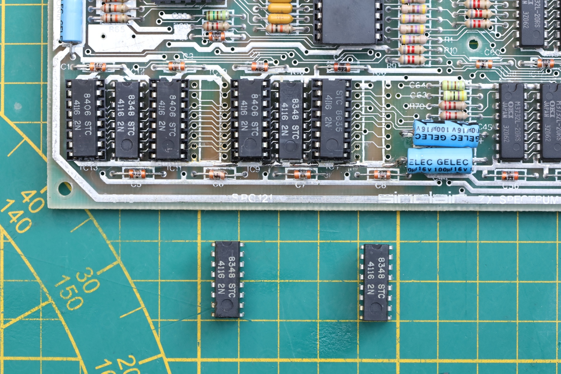
I de-soldered the two chips, while taking the liberty to clean the flux from all adjacent ones. I didn’t know if the short is from the board or from a component -> thus, I needed to see. Testing the two chips reveal a hard internal short, they mess up the voltages of the tester too, it goes berserk when I clamp the chips down.
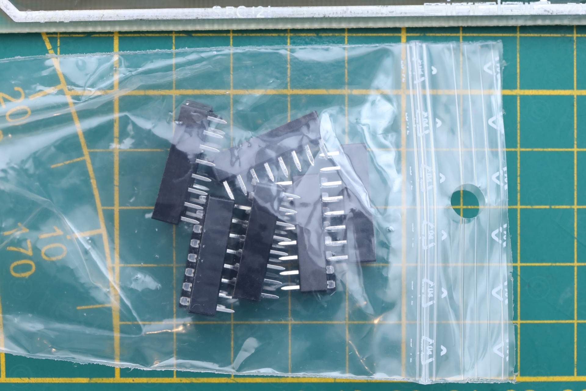
Proceeded to de-solder the other two ICs reported by the Diagnostic ROM, but I can’t fit the round hole socket due to the existing ones not being properly centered. But I didn’t want to stress the board even more, and a cheaper socket did fit.
Unfortunately the ULA is dead, and only shows proper image if the reset button of the Diagnostic ROM board is held pressed. Swapping it to vLA82 produces correct results. This was very confusing to debug. Every time I was resetting the DIAG ROM, the TV image was momentarily correct.
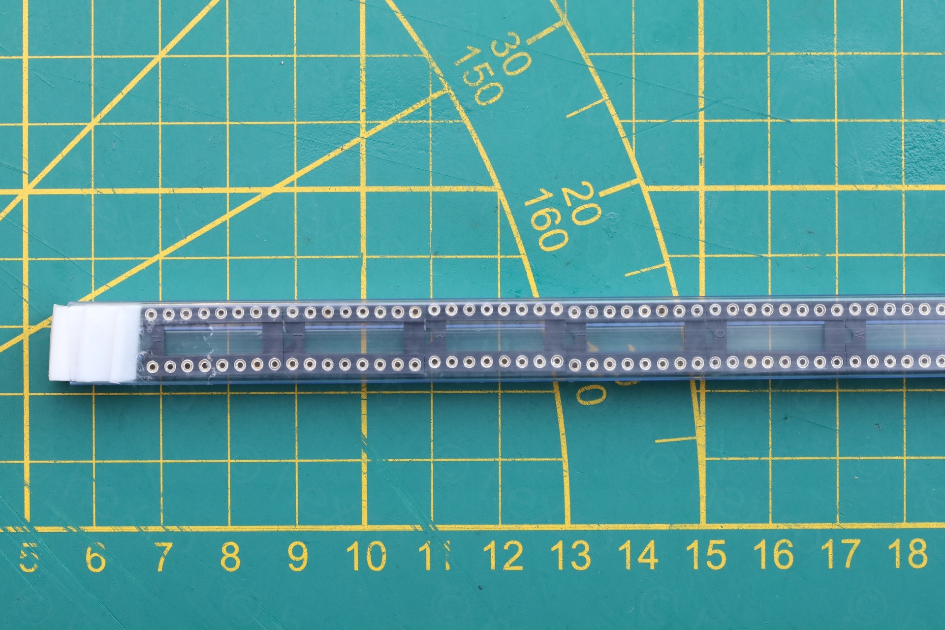
I decided to keep the board and convert it to a test jig for other Sinclair Spectrums, by installing ZIF sockets for main parts.
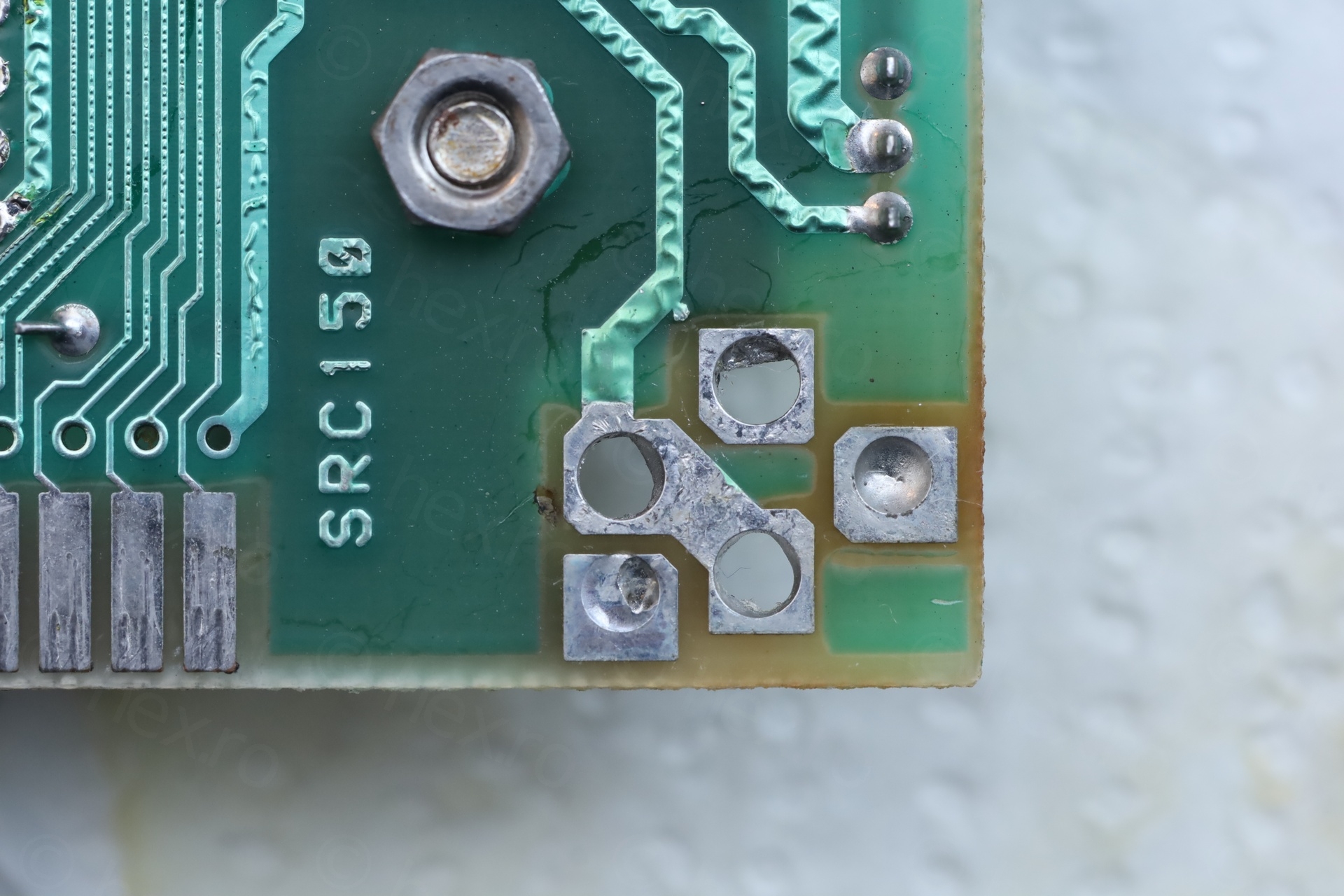
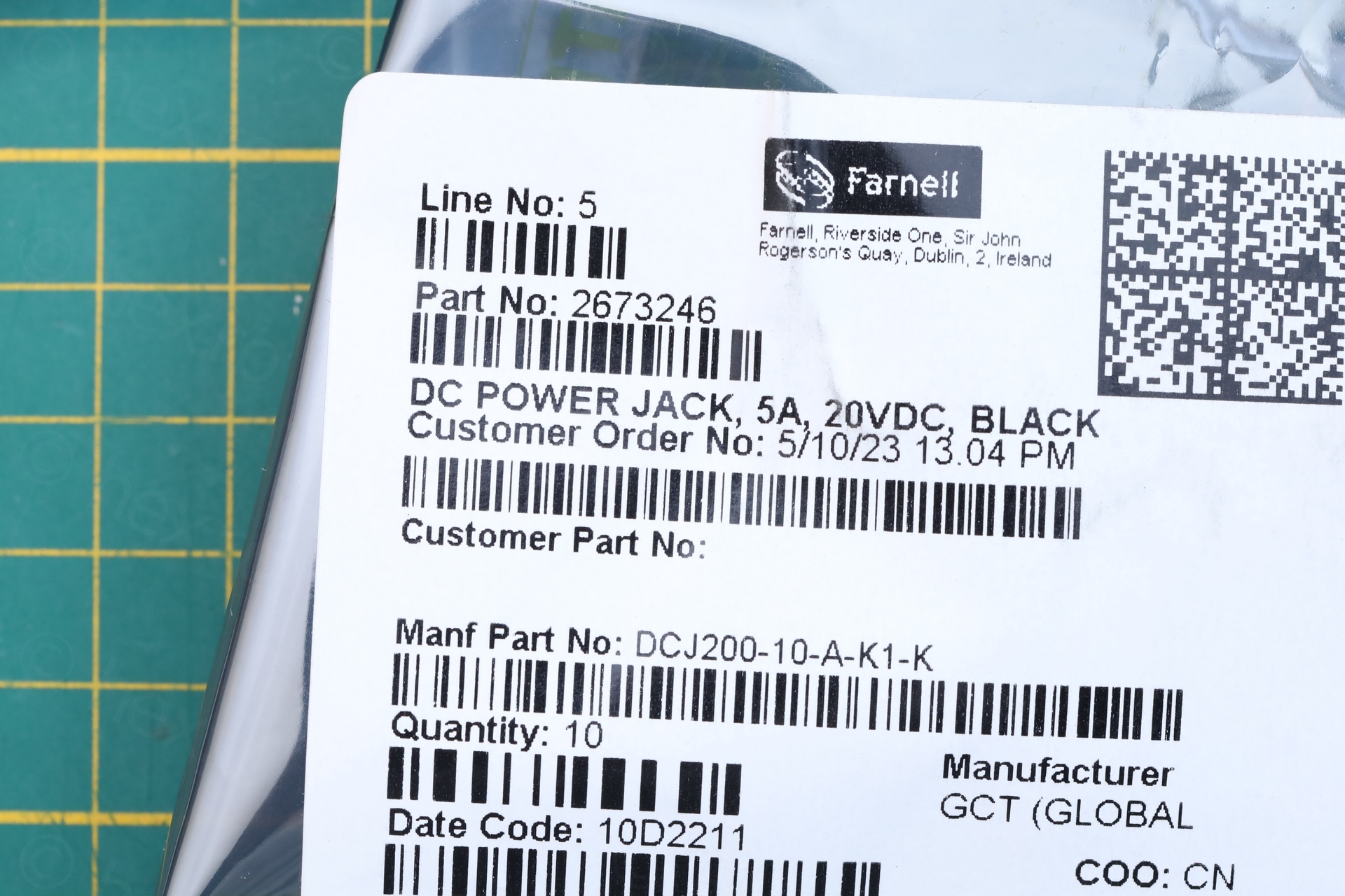
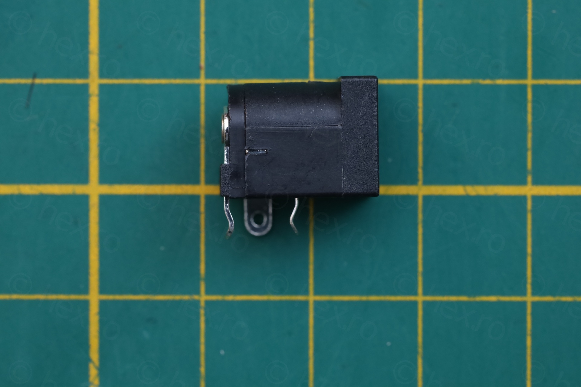
One more step was to replace the 9V power plug:
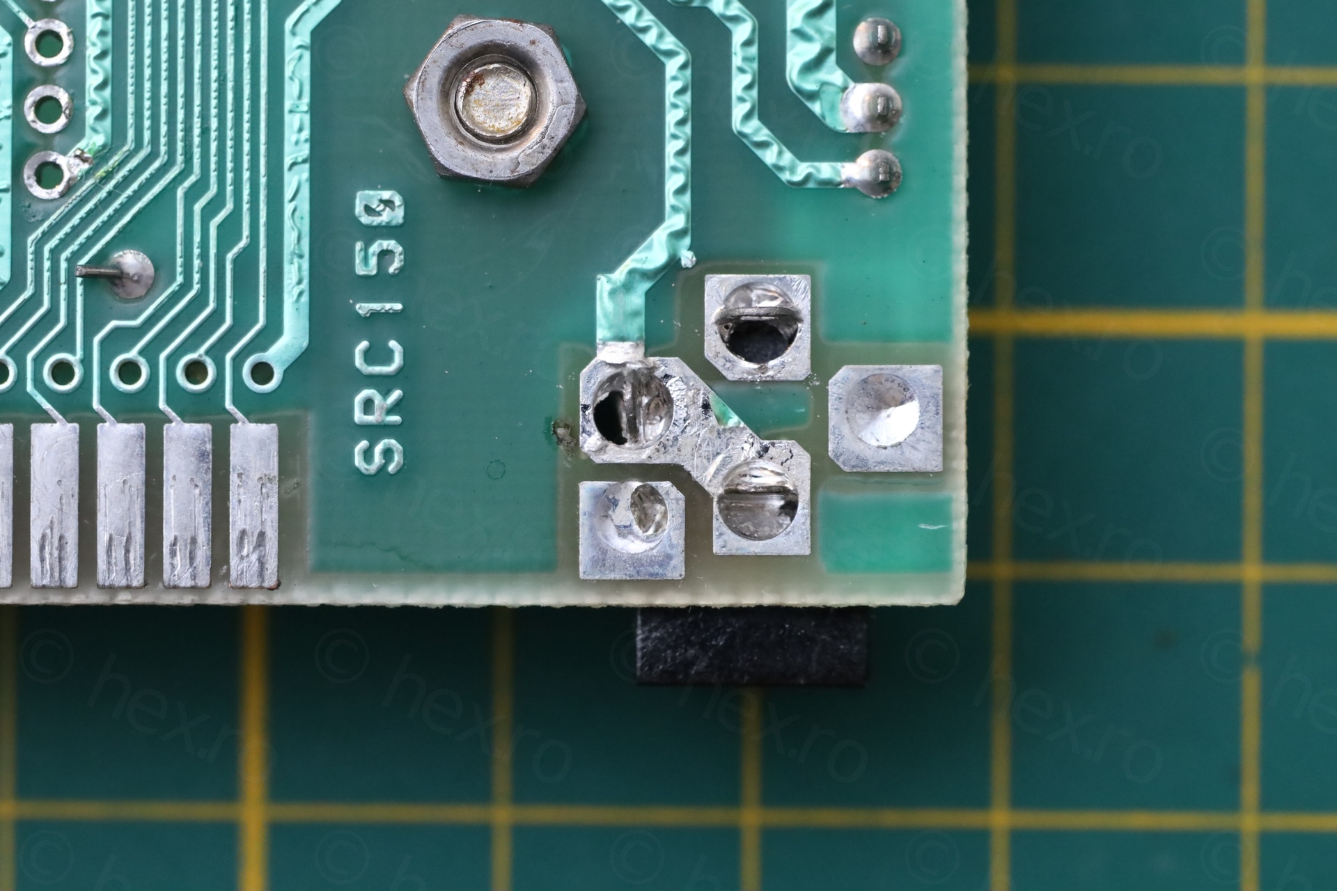
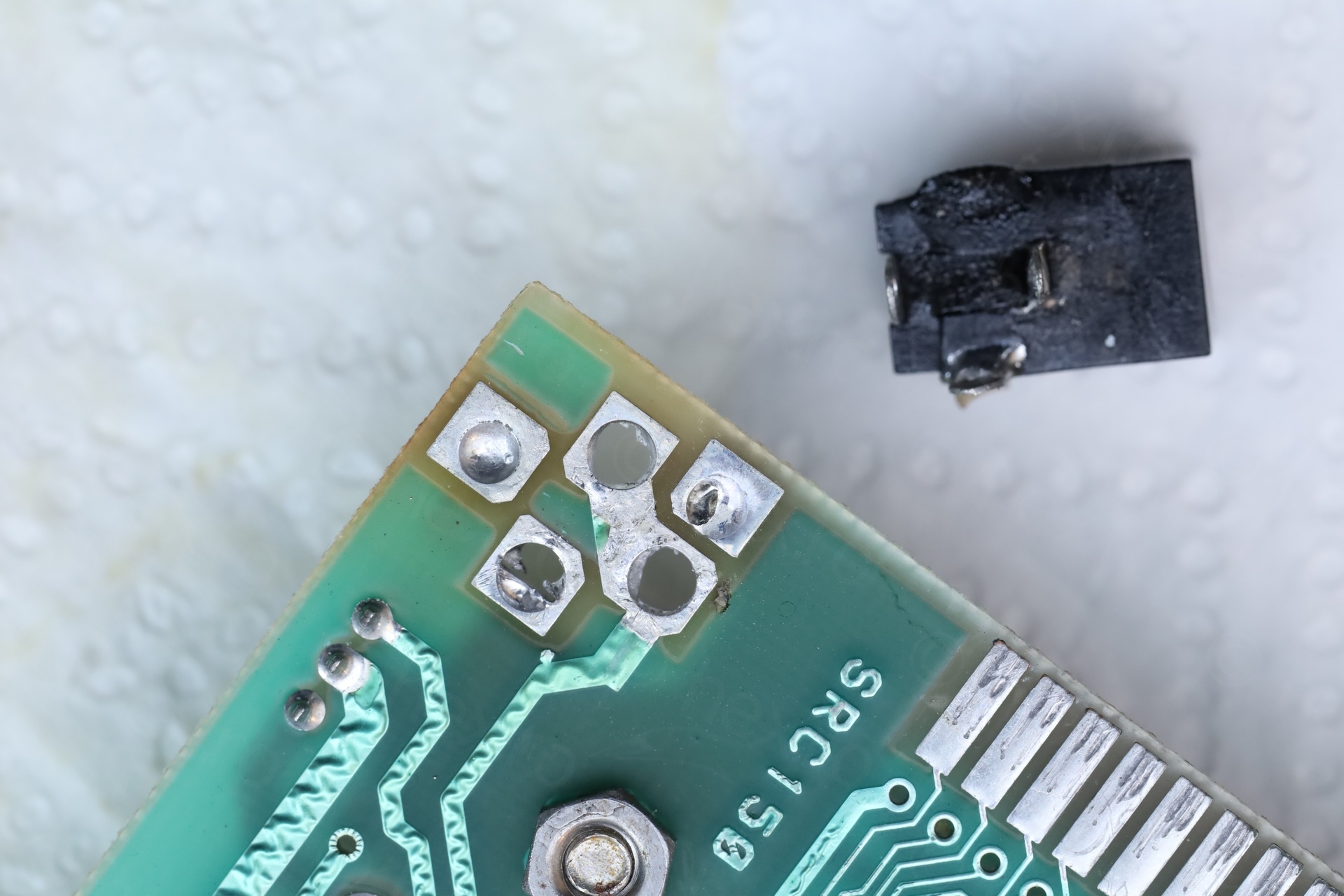
I was able to diagnose the board fully: 4 dead RAM ICs, ULA was bad producing a corrupted image and the power plug was fiddly.
After fixing all the “What is this?” issues:
I will now have to take away the CPU and re-install it in a socket. This way, the board will become a test board that I could swap components easily.
Ivan
BC327 was installed correctly. BC327 pinout is 1: Emitter, 2: Base, 3: Collector
viulian
Thank you, you are right. I got confused with the rotations … I will correct the text.
Ivan
do you ever use BC327 in repairs?
I see people go for BC557 even it has only collector current of 100mA
viulian
I did check alternatives when I started, but once I found the ZTX790ASTZ, I stuck with that and mostly for aesthetics. Thus, I didn’t try other transistors..