
This is a story of replacing capacitors on a computer motherboard found at the flea market.
Table of Contents
The Find
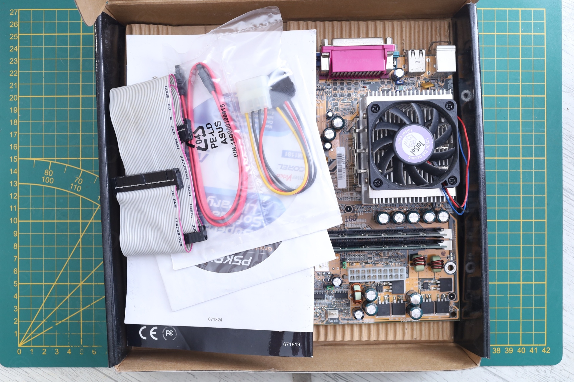
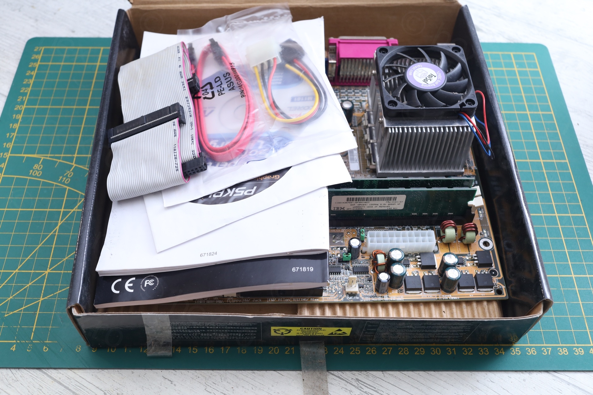
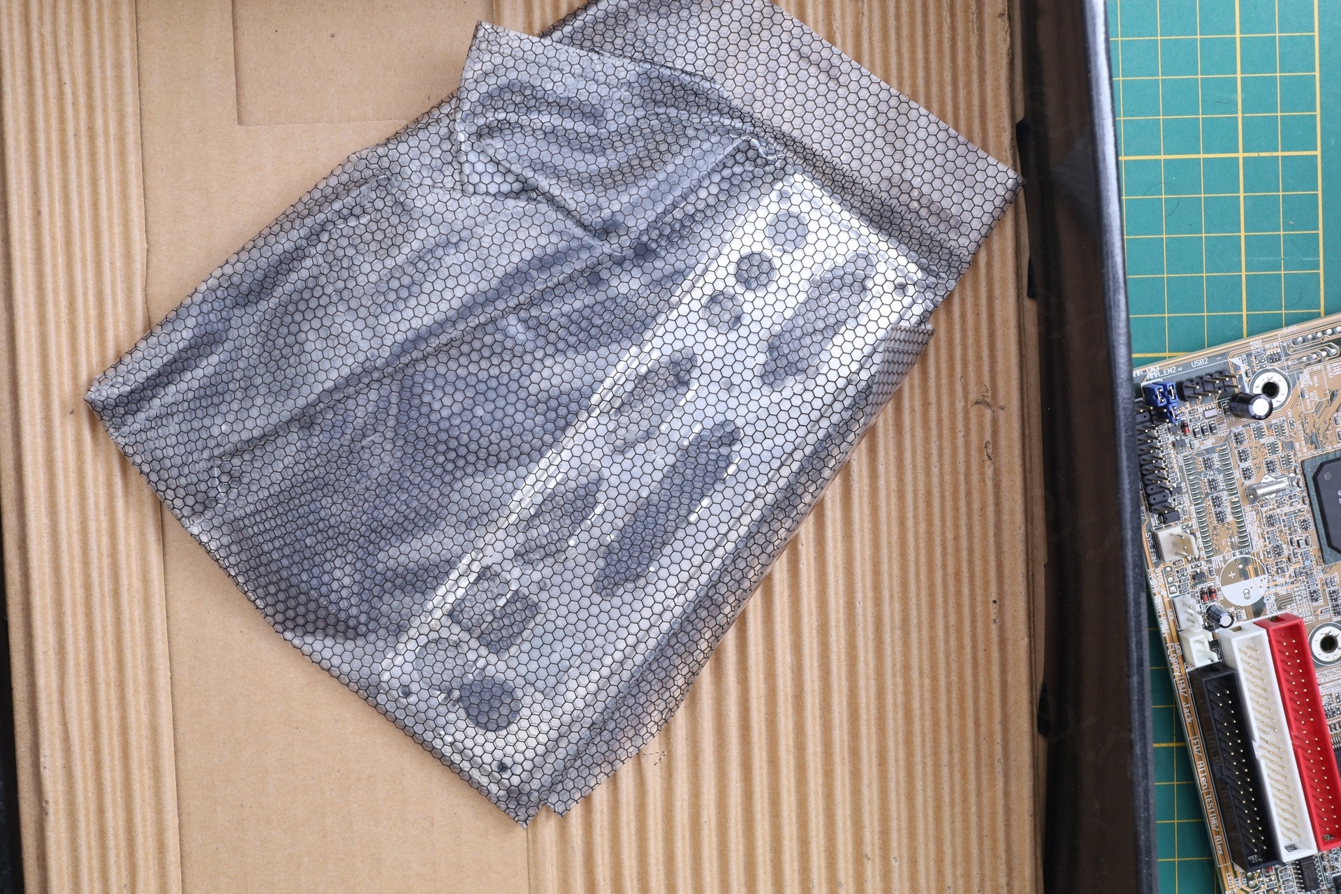
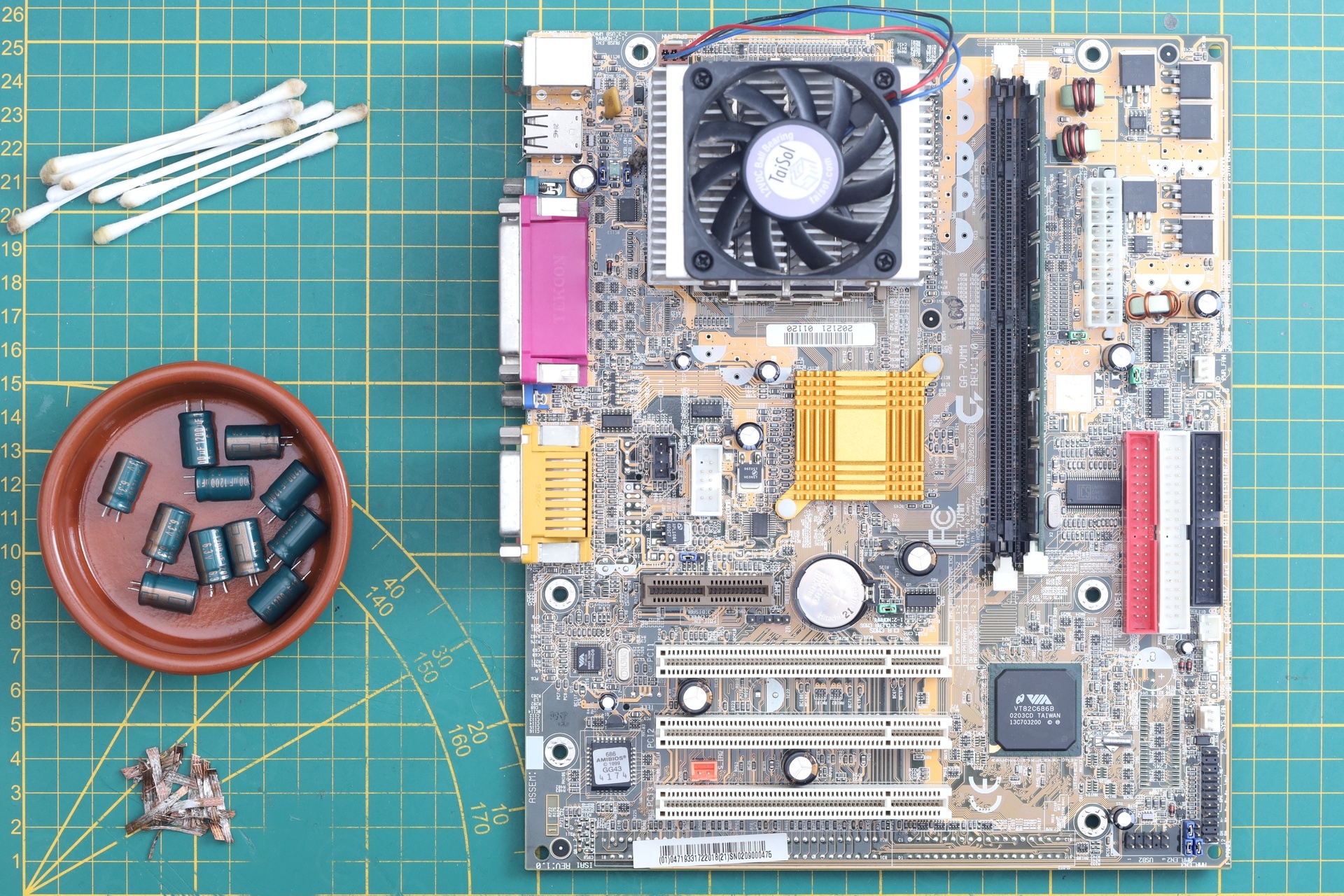
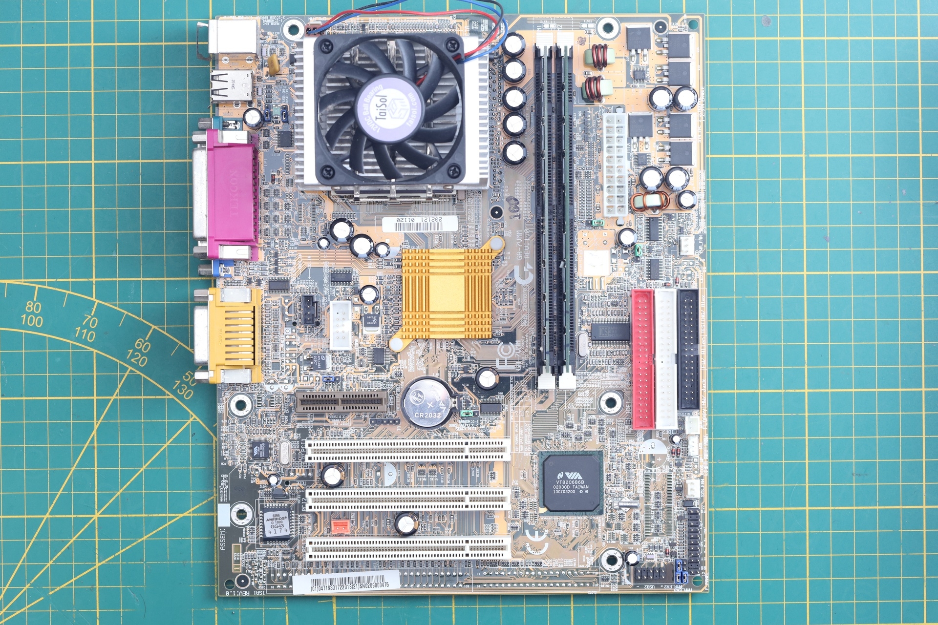
I spotted the motherboard on top of a cardboard box. Finding old computer parts is rare, finding in original box is borderline strange. I had a quick look: it wasn’t corroded, had the IO shield, the CPU heat-sink was installed (one would assume there was some sort of a CPU underneath it too), the memory was also installed..
Plus, the price was great. What sold me was the IO shield and it being complete . Parts aren’t necessarily expensive, but ordering from few different sellers would make shipping very expensive.
At home, the first disappointment:
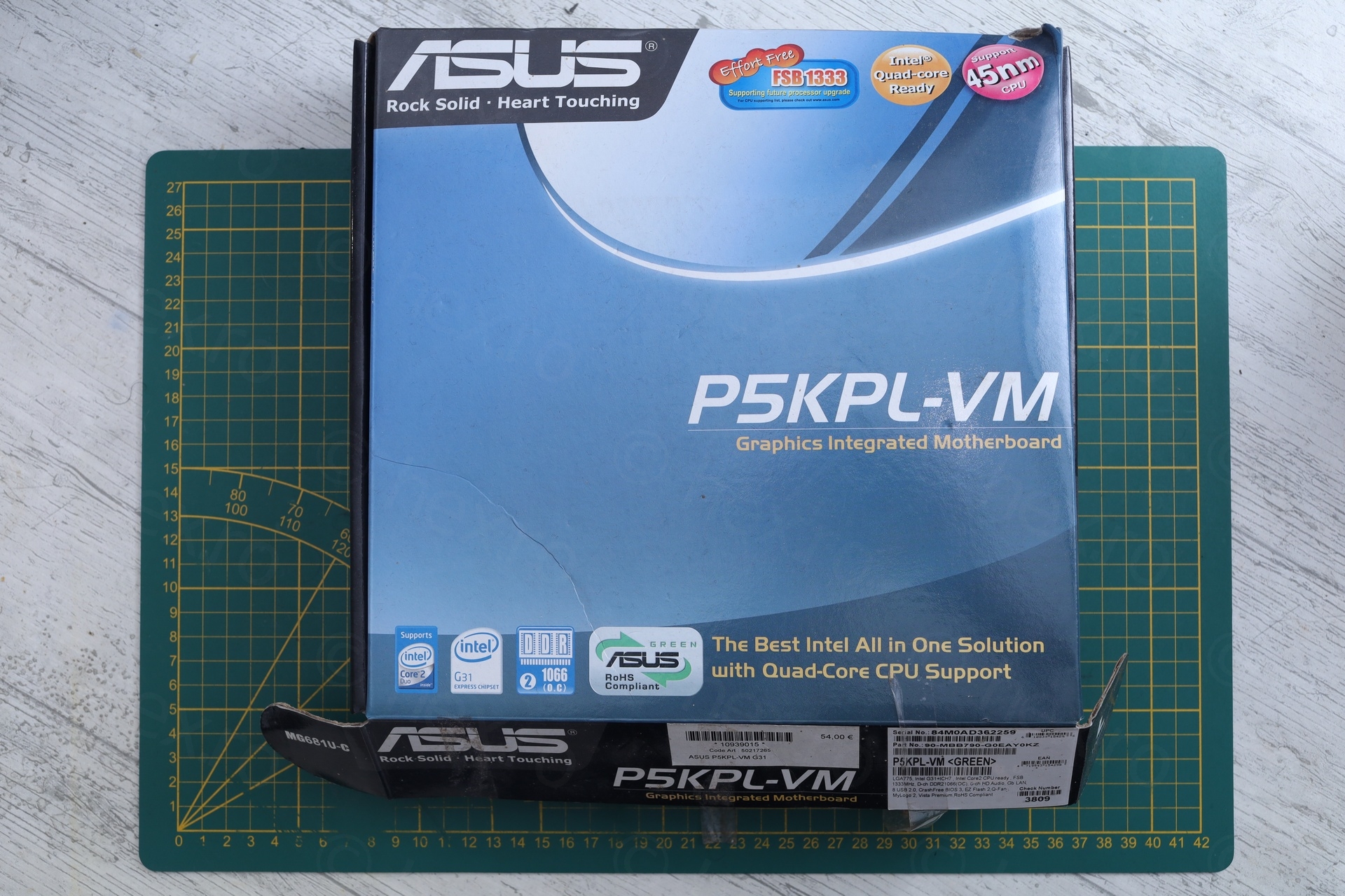
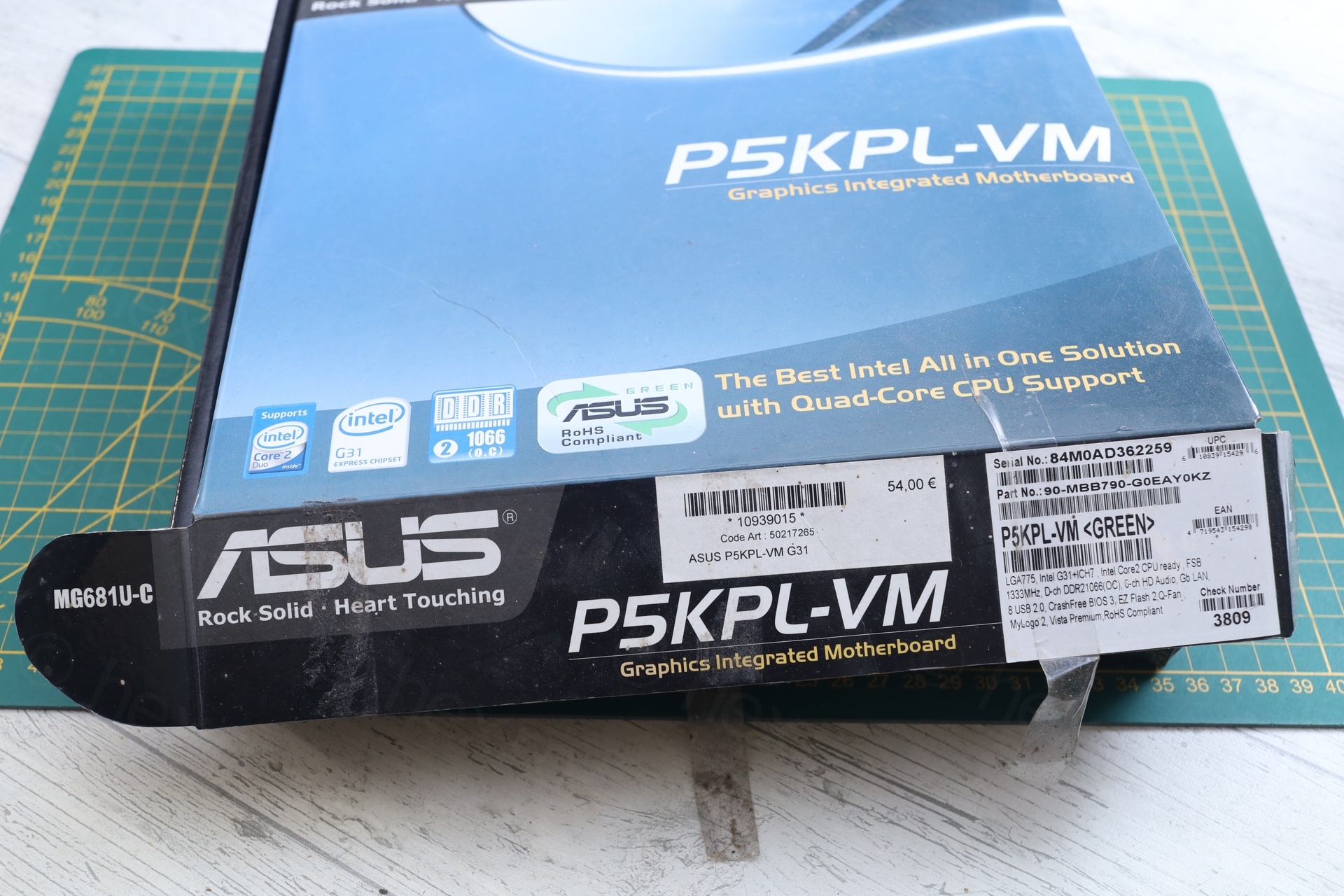
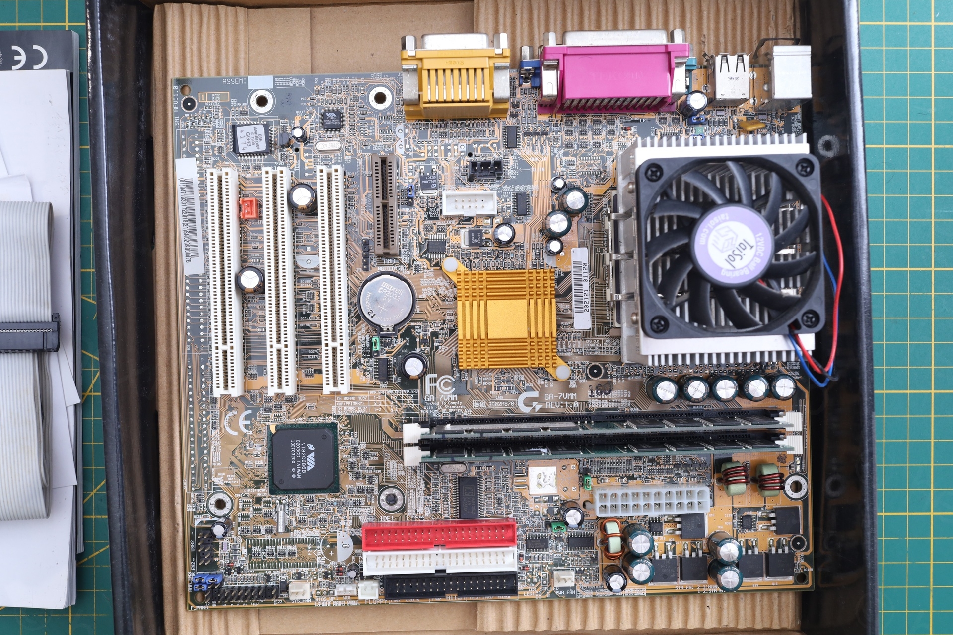
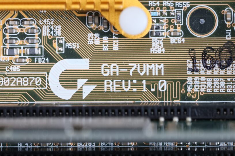
The case was from an Asus P5KPL-VM motherboard, but inside, there was a Gigabyte GA-7VMM motherboard.
The Problem
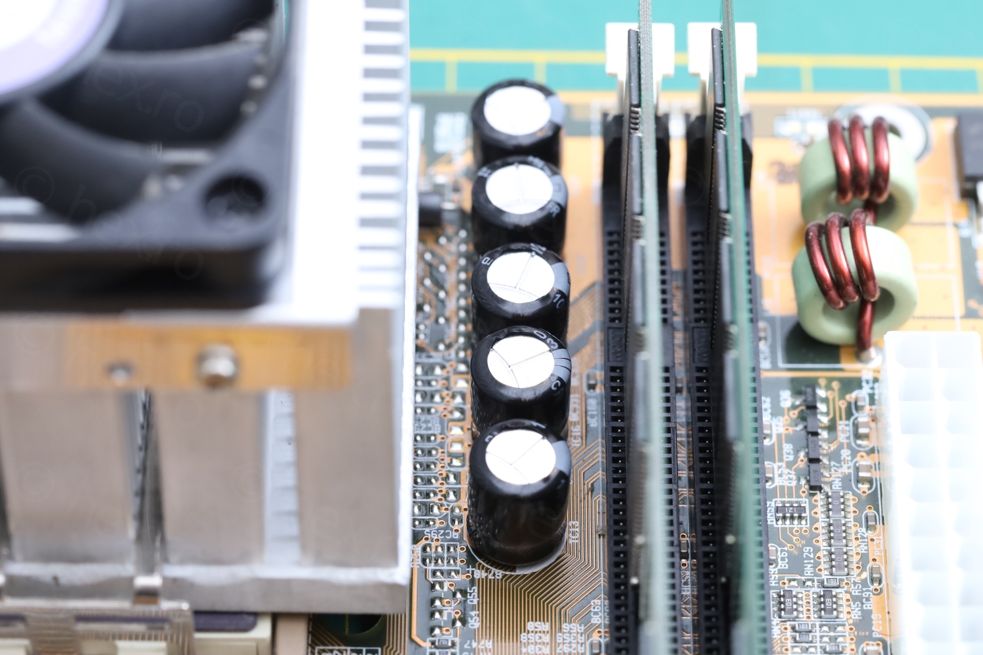
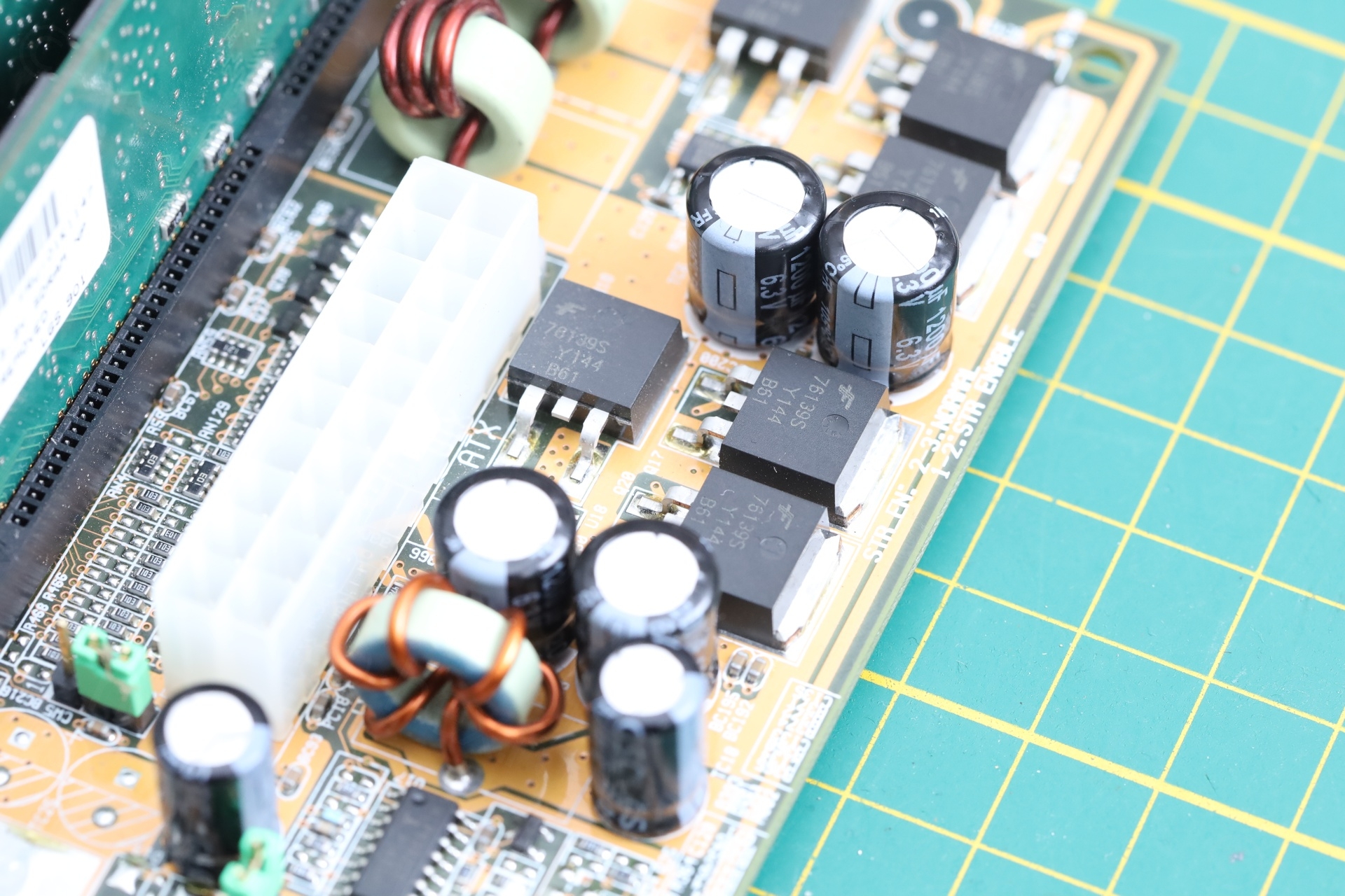
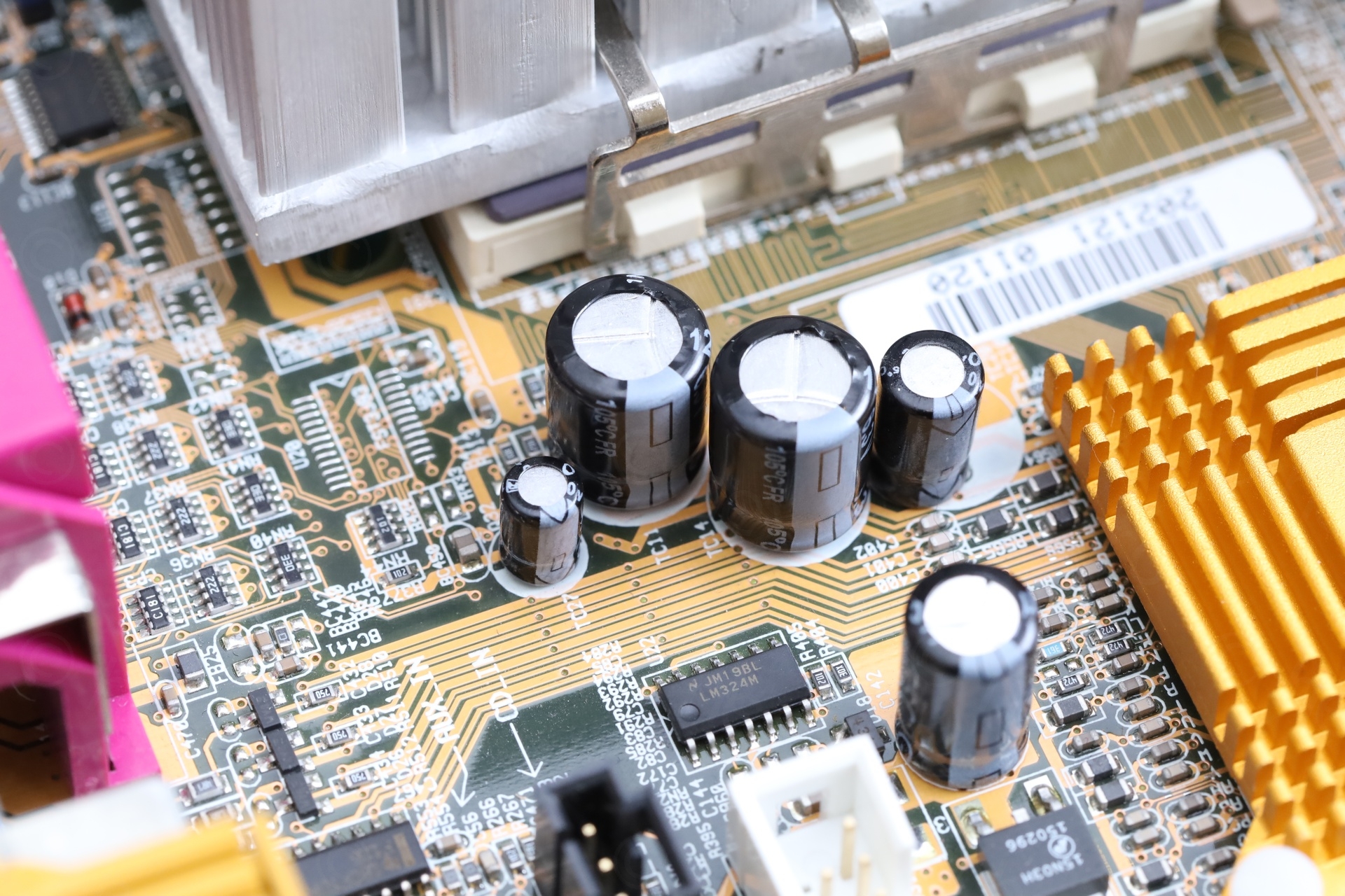
Having a quick visual inspection, a second disappointment .. some capacitors were swollen:
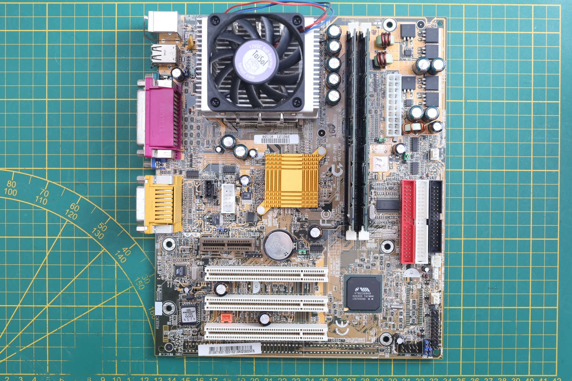
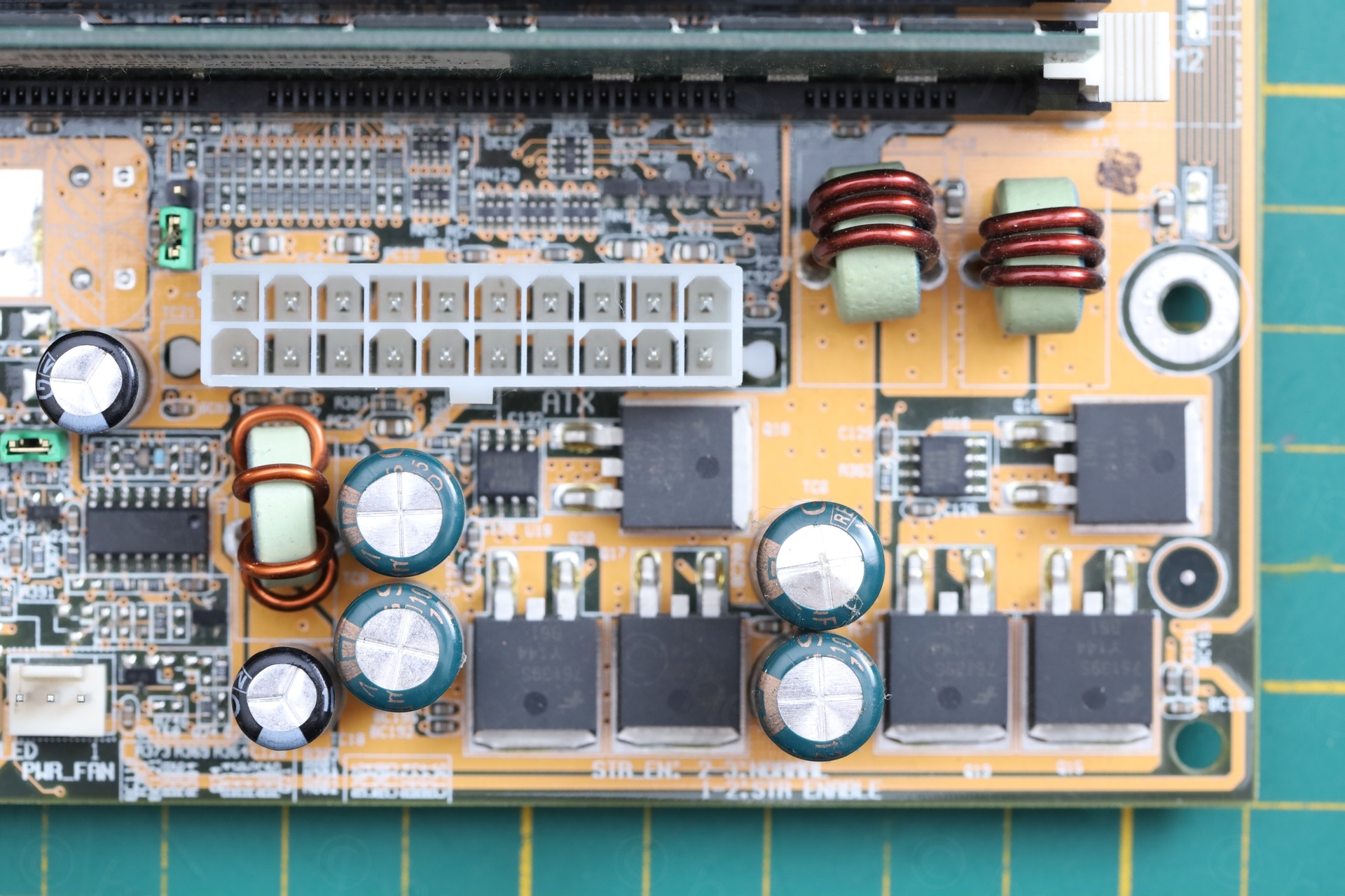
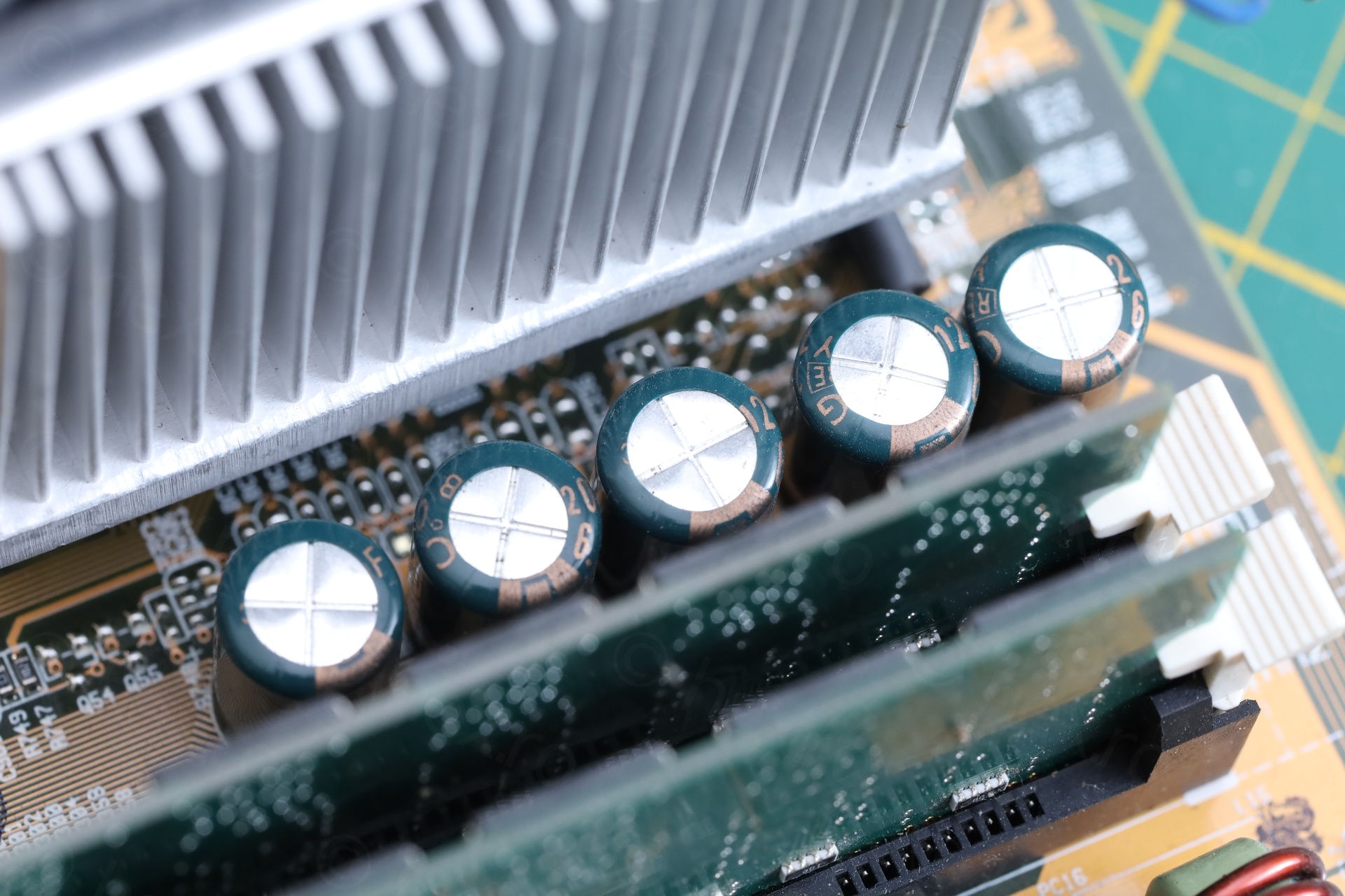
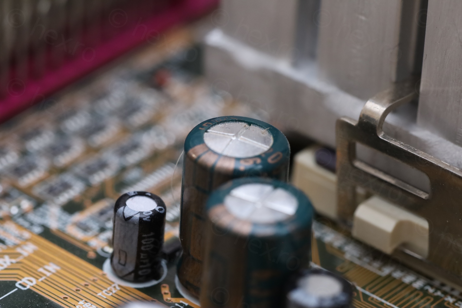
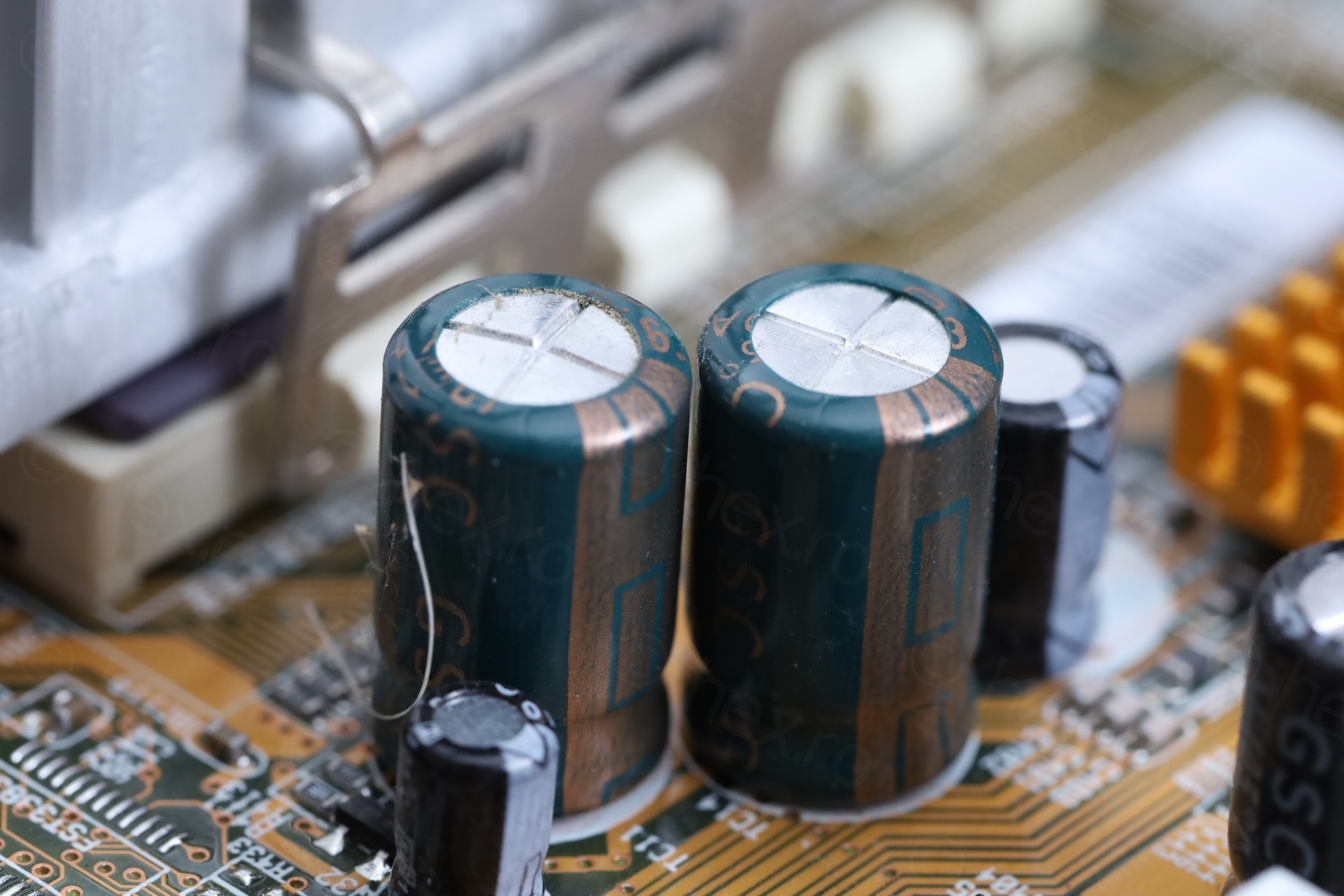
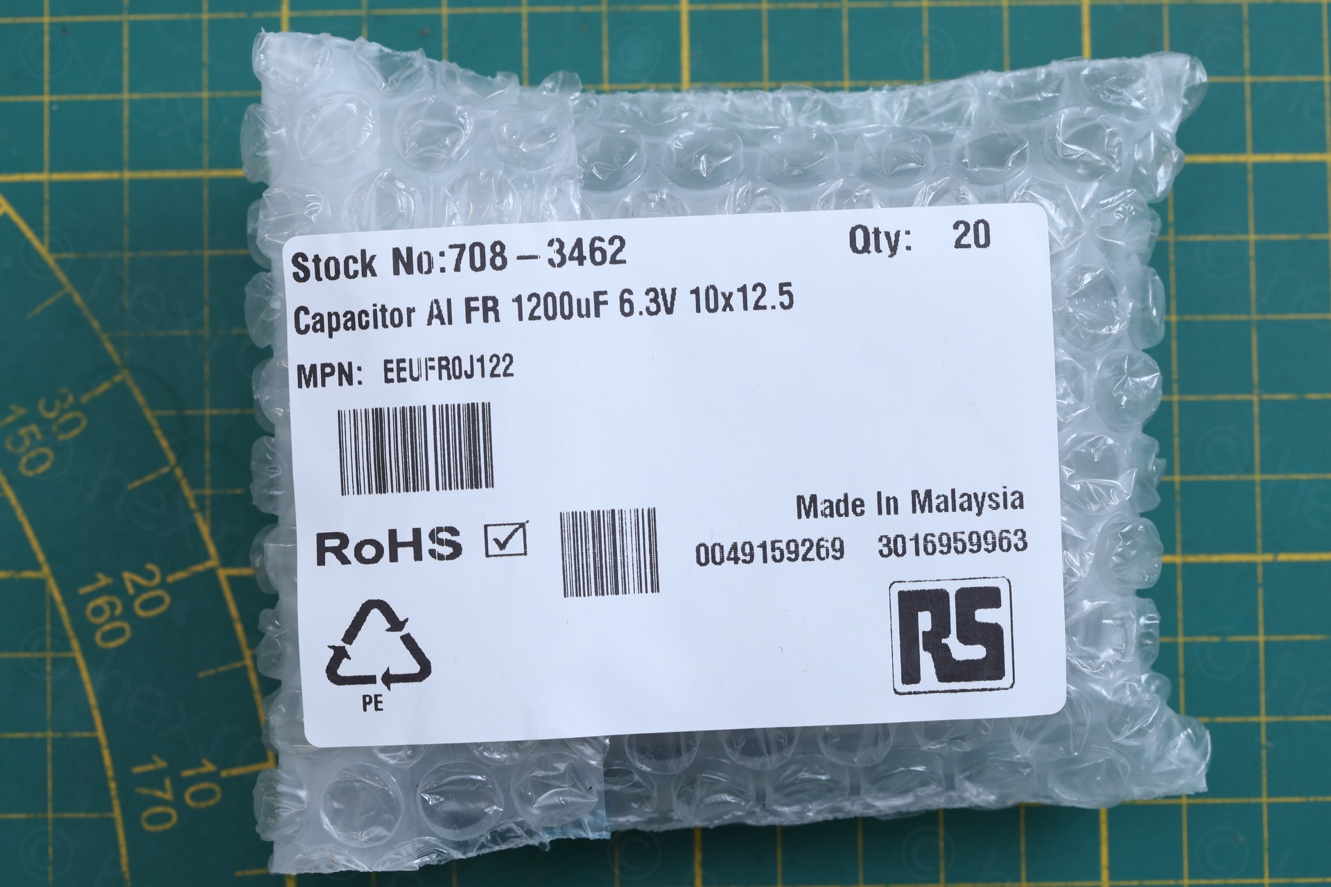
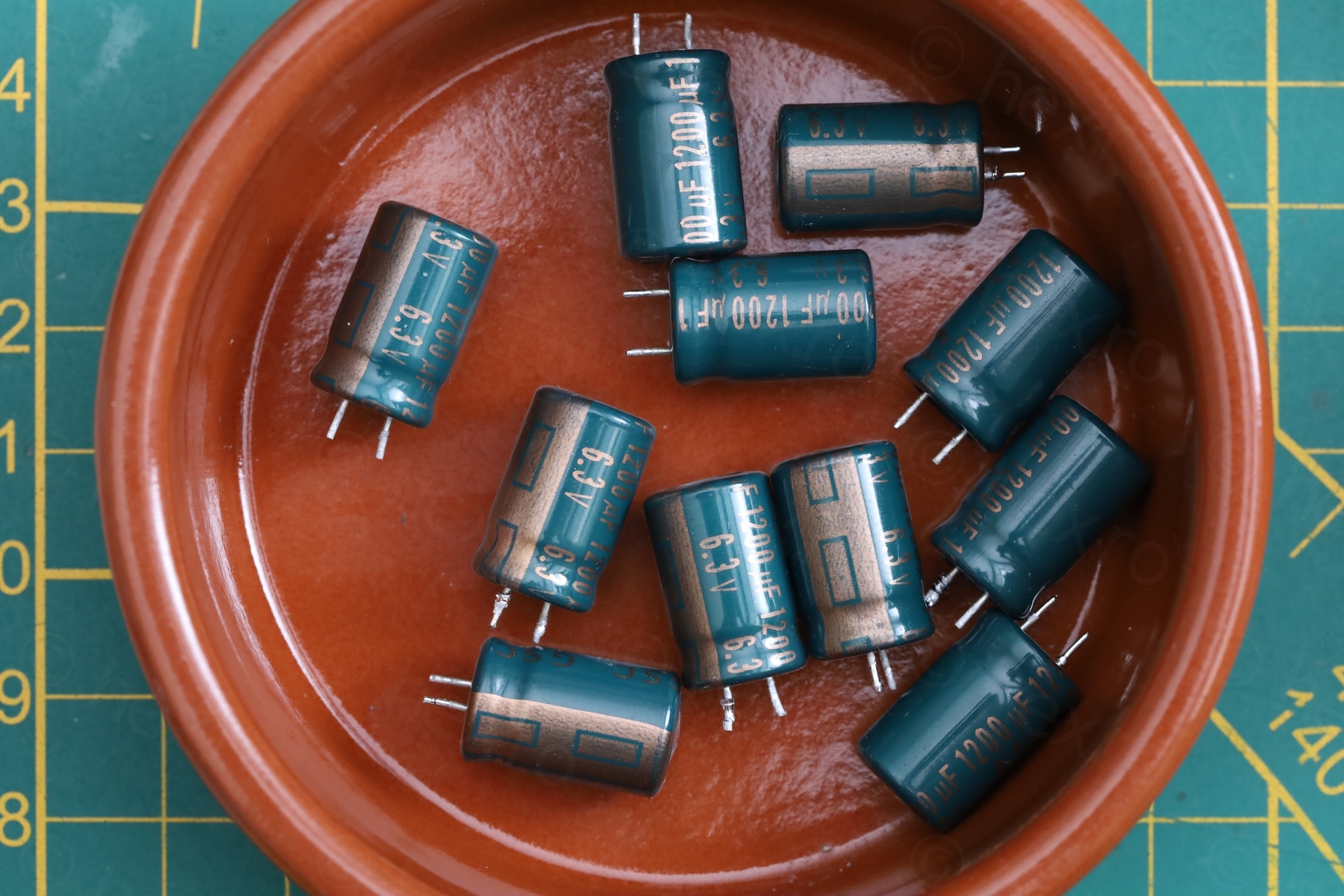
The swollen capacitors were 1200uF @ 6.3V and green. As luck would have it, all the green capacitors were the same spec, and few were already bulging – thus easy decision. I’d have to replace all green capacitors.
I took some measurements (5mm lead spacing, 10mm diameter) and ordered some replacements in the form of Panasonic EEUFR0J122 – 1200uF @ 6.3V, 6000 hours and 10mm diameter.
The Extraction
It was difficult to replace them – the goal was to try not to scar the motherboard.
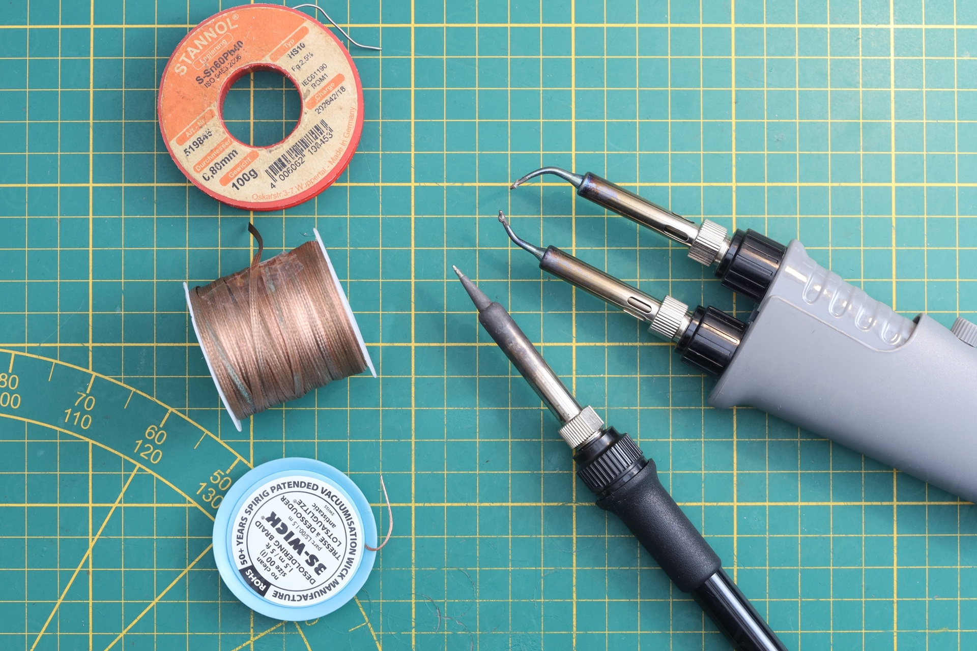
I don’t like to use the electrical vacuum solder sucker on modern motherboards. The round metallic hot tips are wider than the pins and they scar the circuit board, as it is very tempting to do the circling moves around the lead.
Thus, enter the solder braid, the de-soldering tweezers and the standard hot iron:
There were challenges.
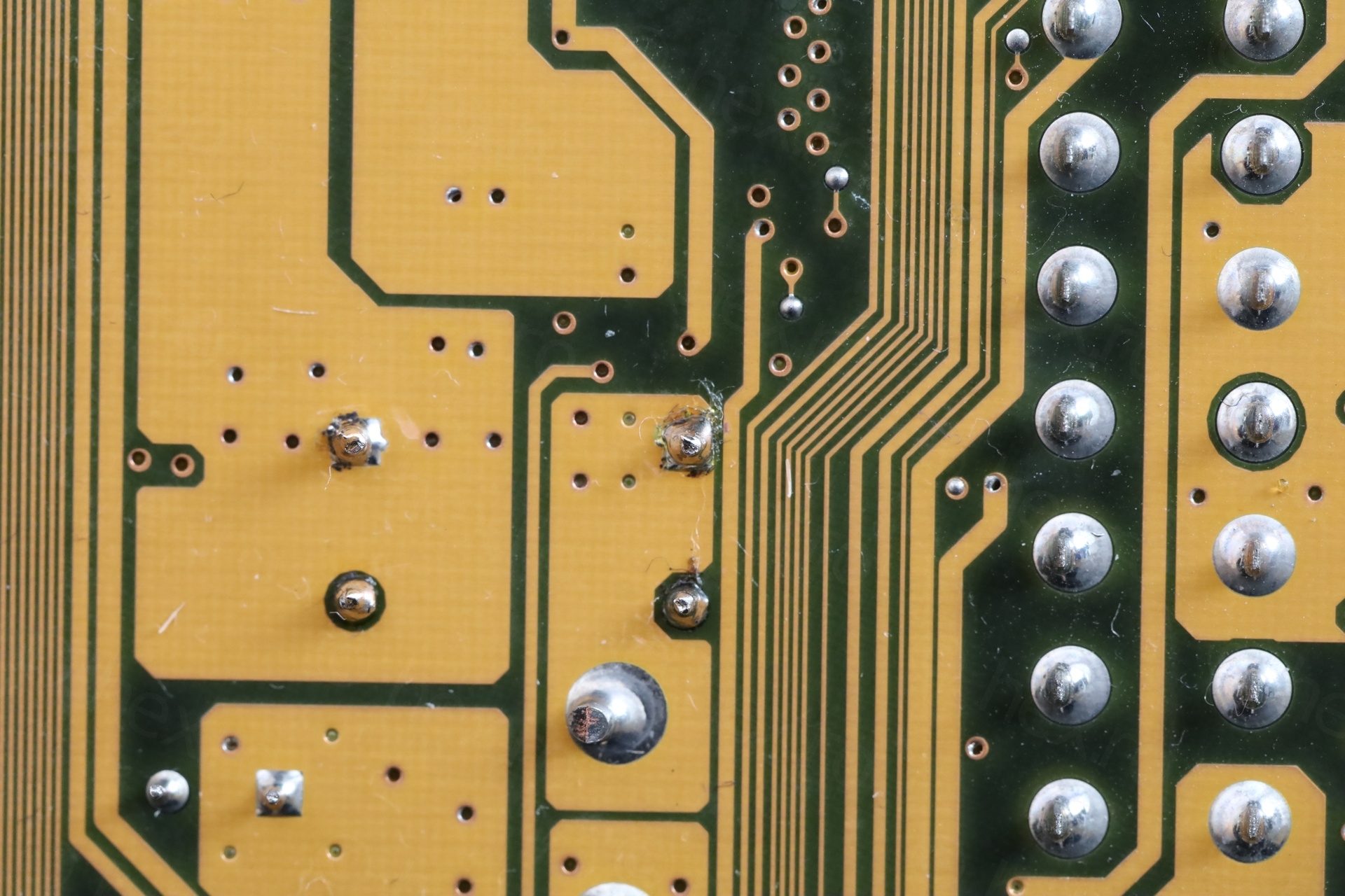
The holes / VIAs tolerances were too tight: some solder was stubborn and stayed inside the VIA – not being absorbed by the solder braid irrespective of how much flux I used. Adding more solder to make it easier to re-de-solder didn’t seem to help.
The next option was to pull the capacitor by hand while applying heat to both leads the same time. Problem ? The de-soldering tweezers are made for SMD components and not very powerful. The motherboard is capable of absorbing a lot of heat especially via the GND lead of the capacitor. Thus, it took “forever” to wait for the GND lead solder to melt and by that time the capacitor itself was burning hot to touch and pull. The tips of my fingers hurt for few days..
Third step was to use the normal de-soldering iron to clear the VIAs. Since the de-soldering iron is 90W, this went smoother and I was able to clear them easily with the solder braid and flux. Only few turned out to be a bit more stubborn – and I had to spend a bit more time to clear them properly.
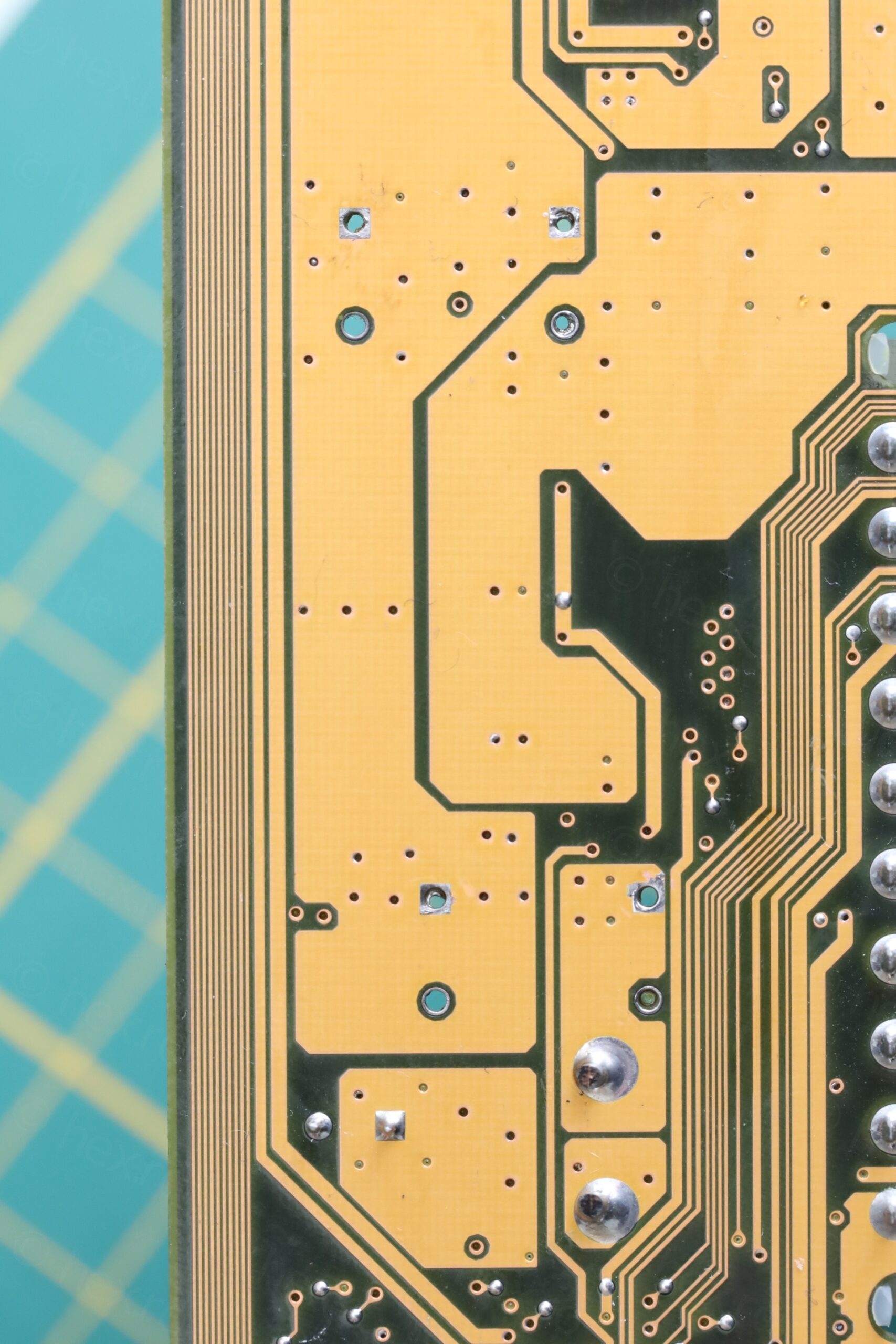
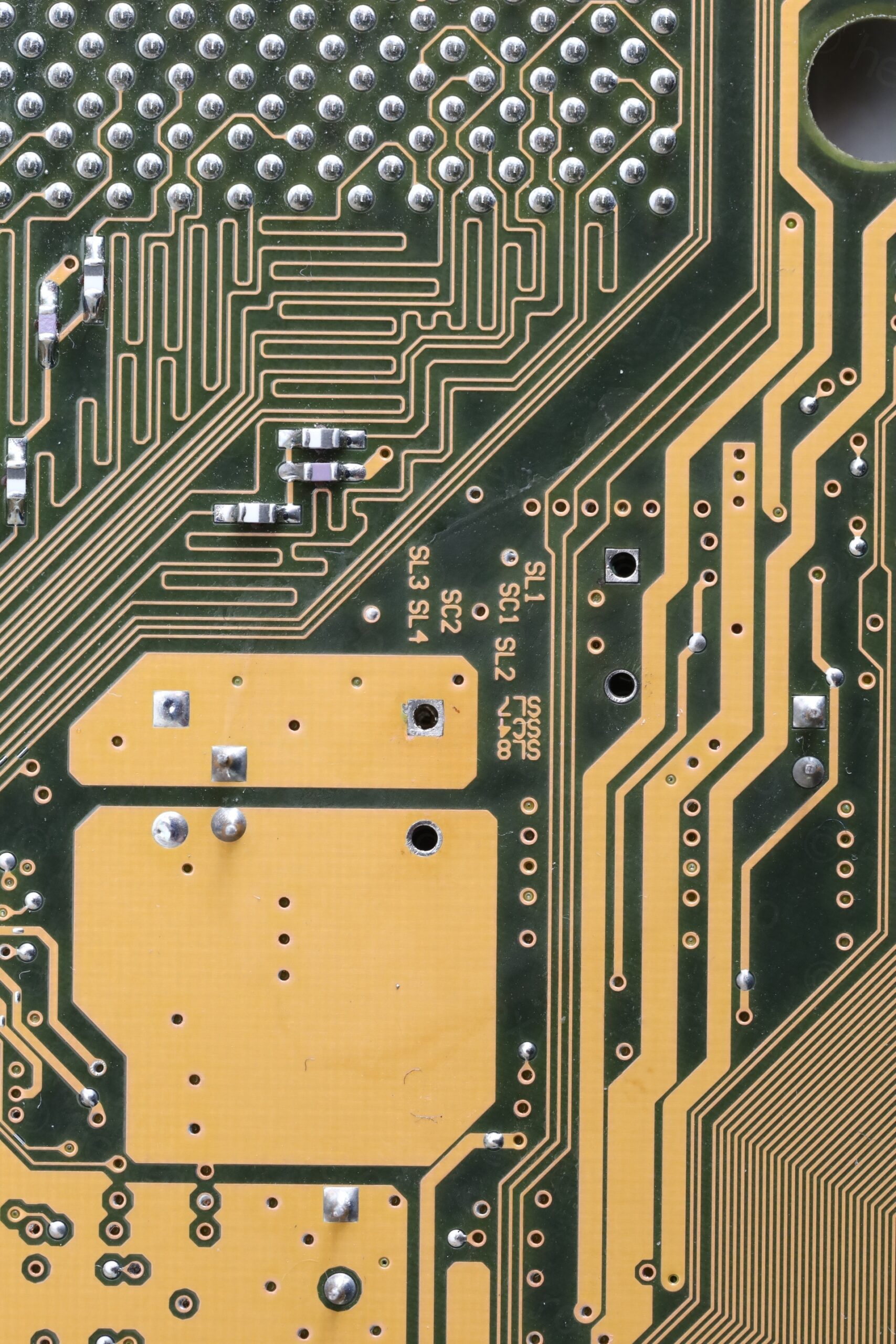
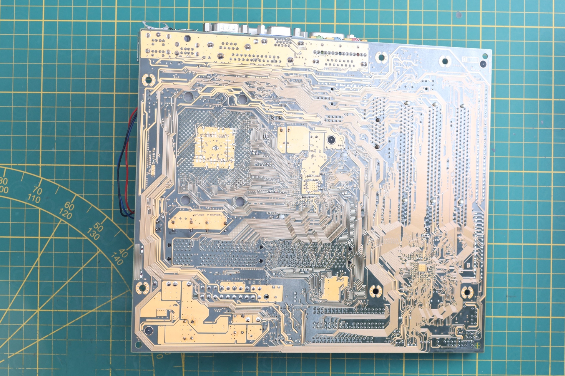
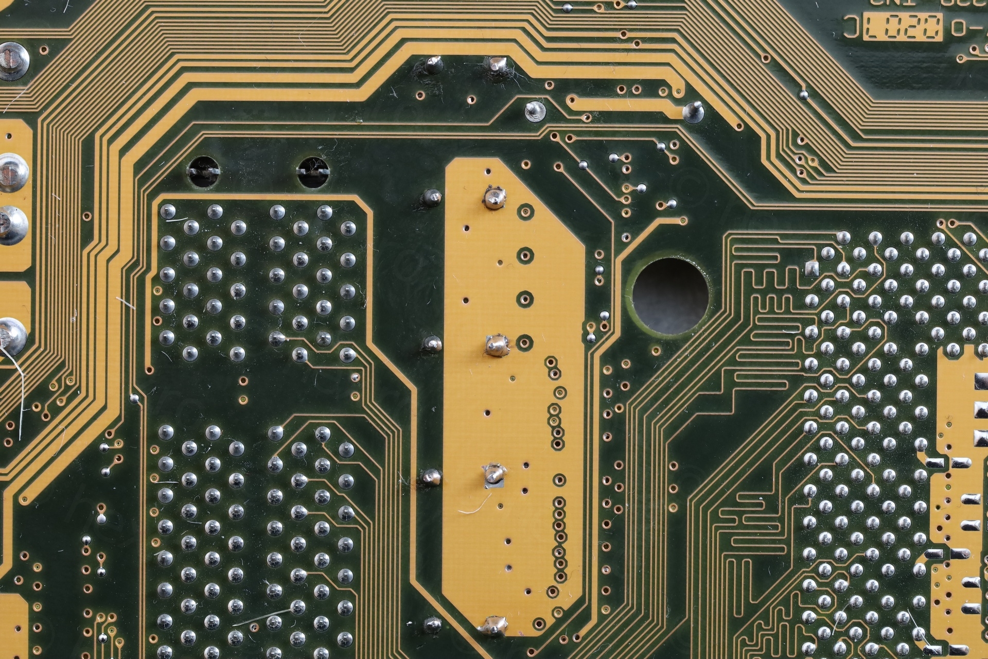
A closer look:
The Rescue
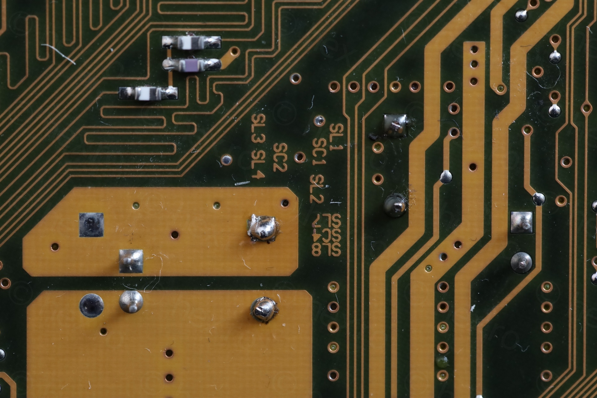
Installing the new capacitors was a breeze, helped by the polarity markings already present on the motherboard. I did have photos, but it was easier with the markings.
A closer look:
The Boot
I didn’t want to start the board with swollen capacitors or mess with the heatsink until I knew if the board worked.. It is a thankless job to replace capacitors just to find out it wouldn’t boot due to some other dramas going on.
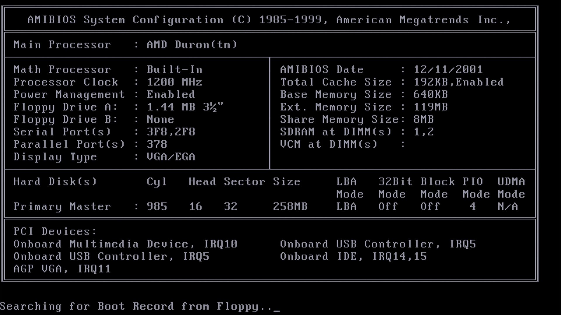
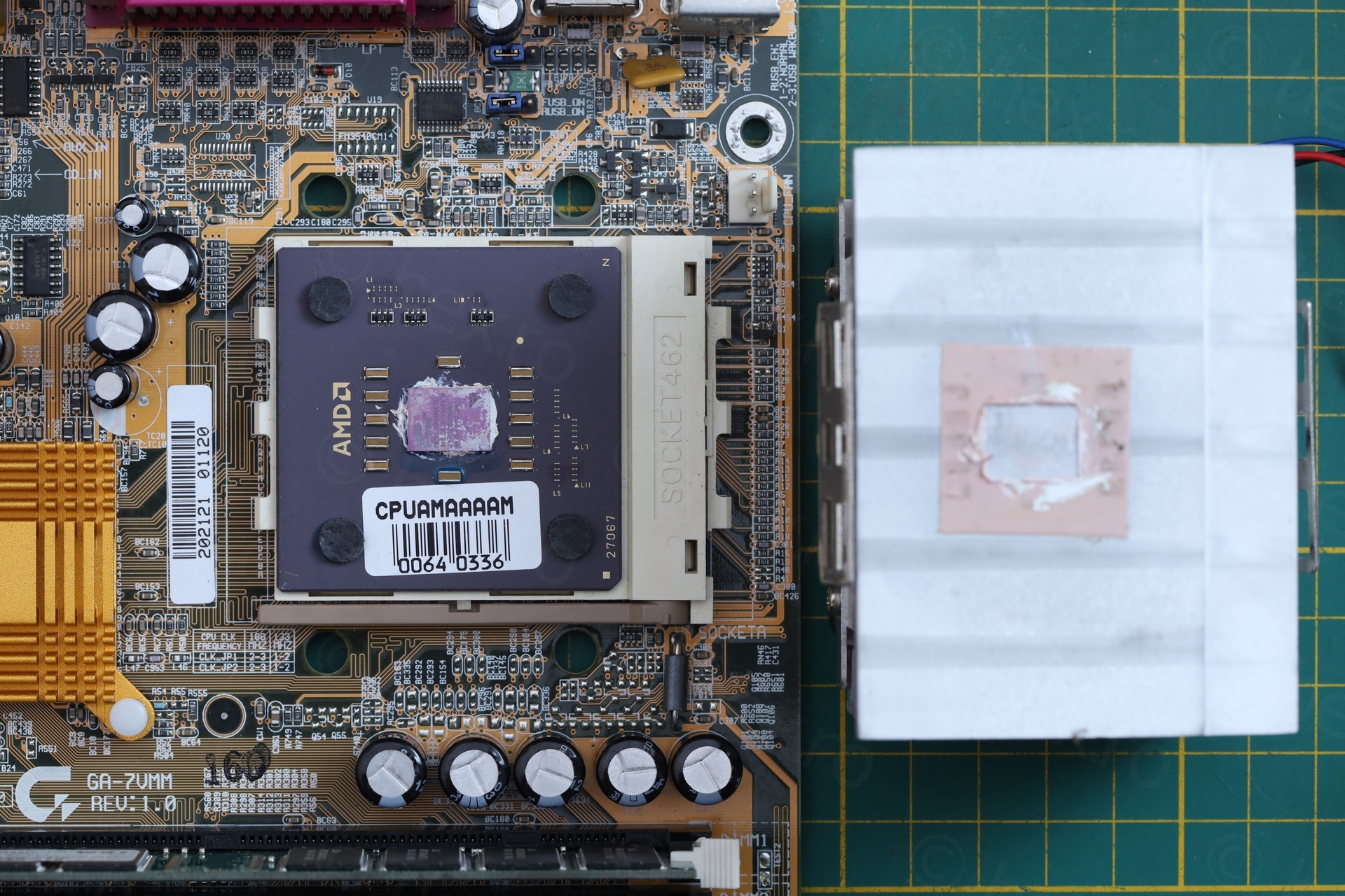
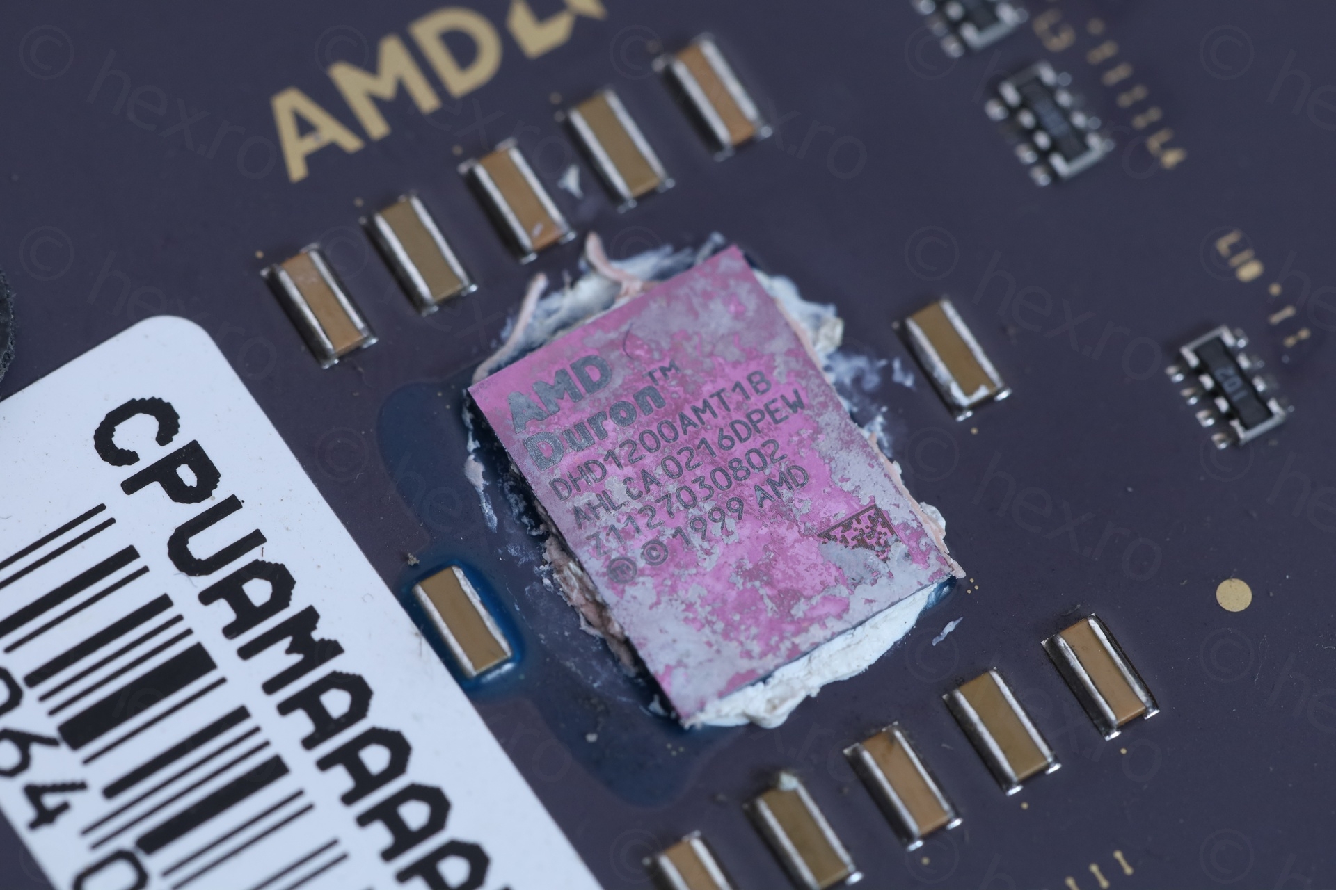
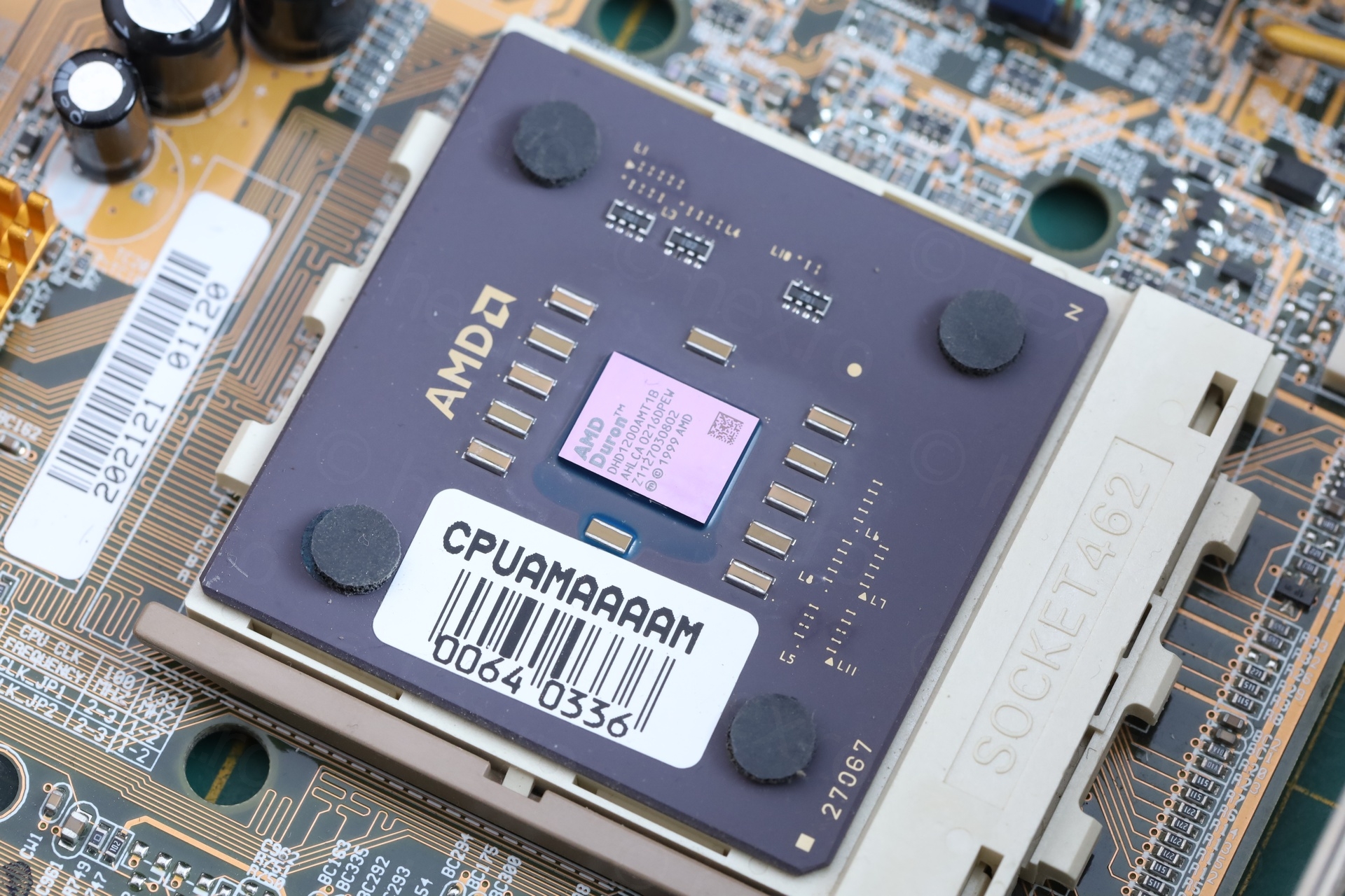
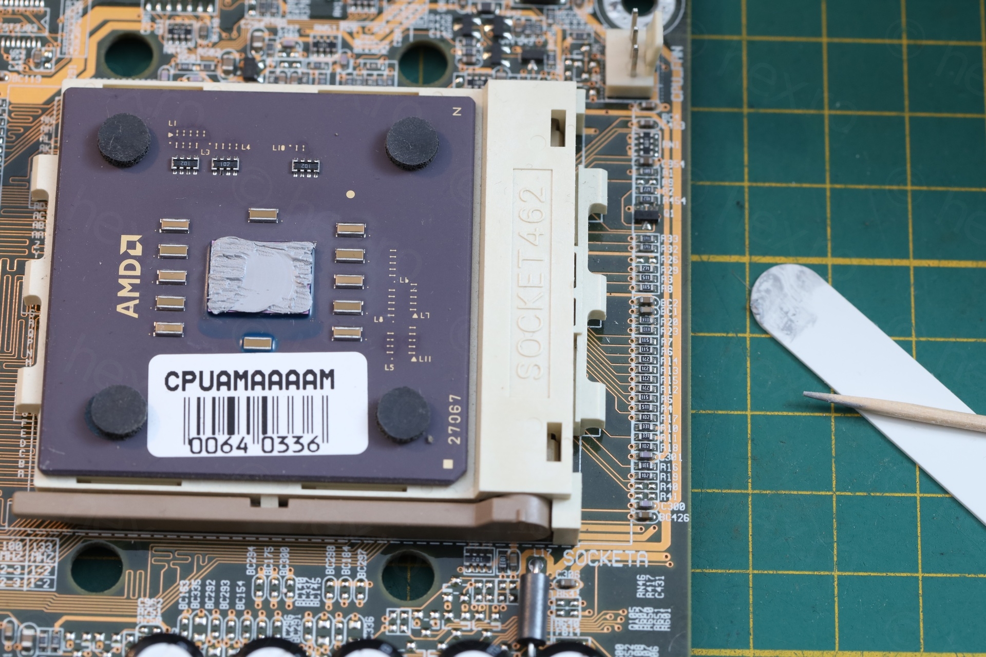
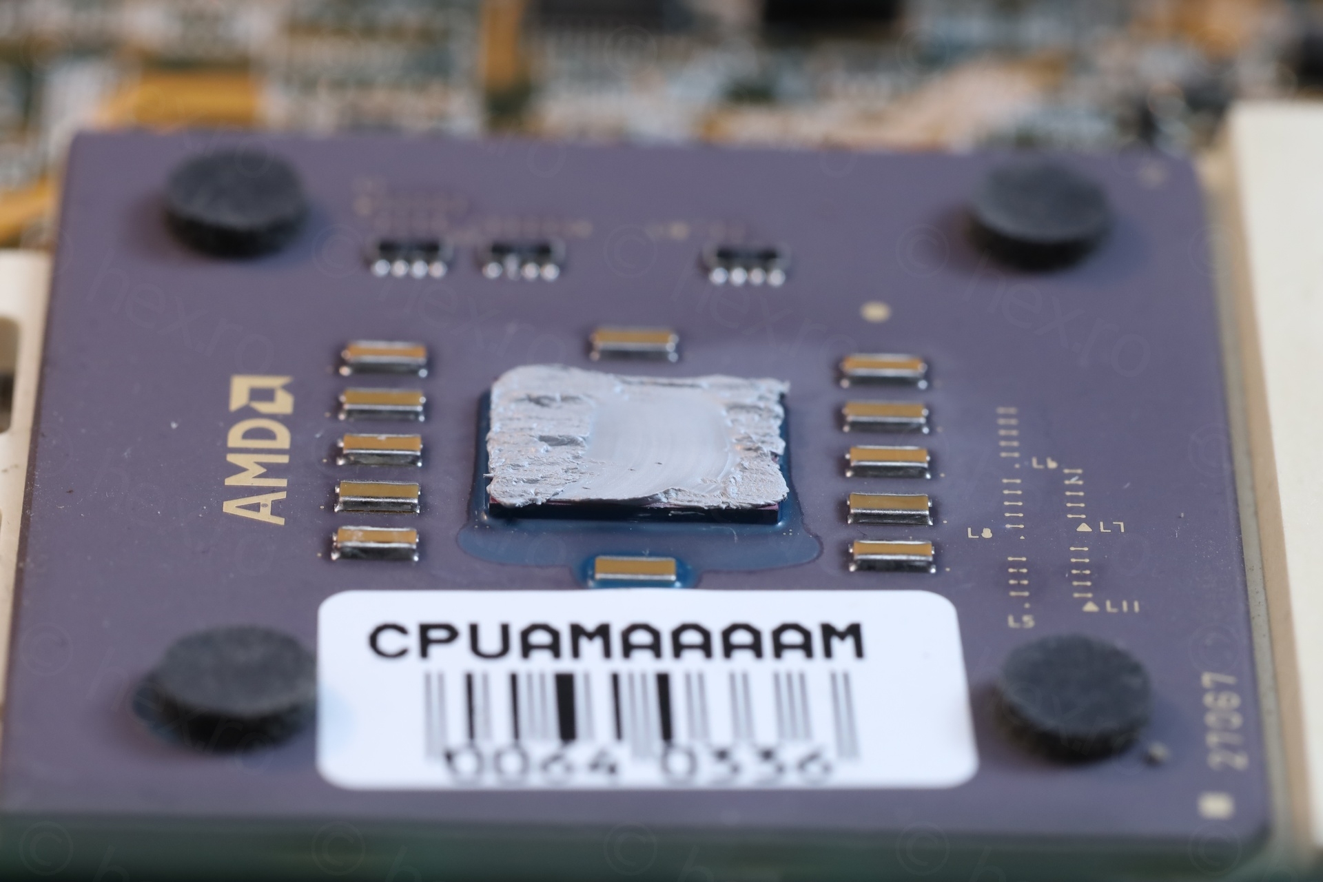
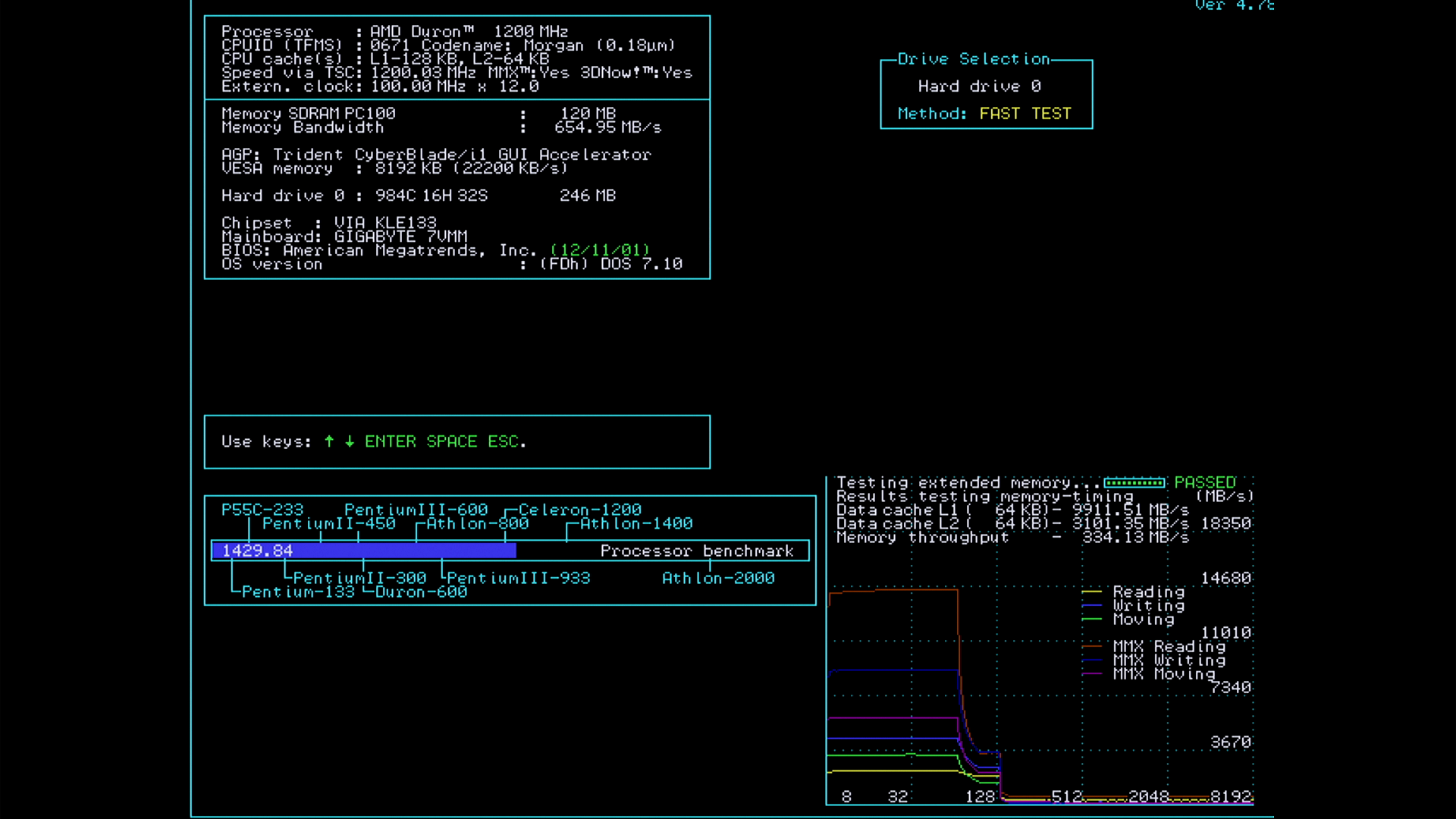
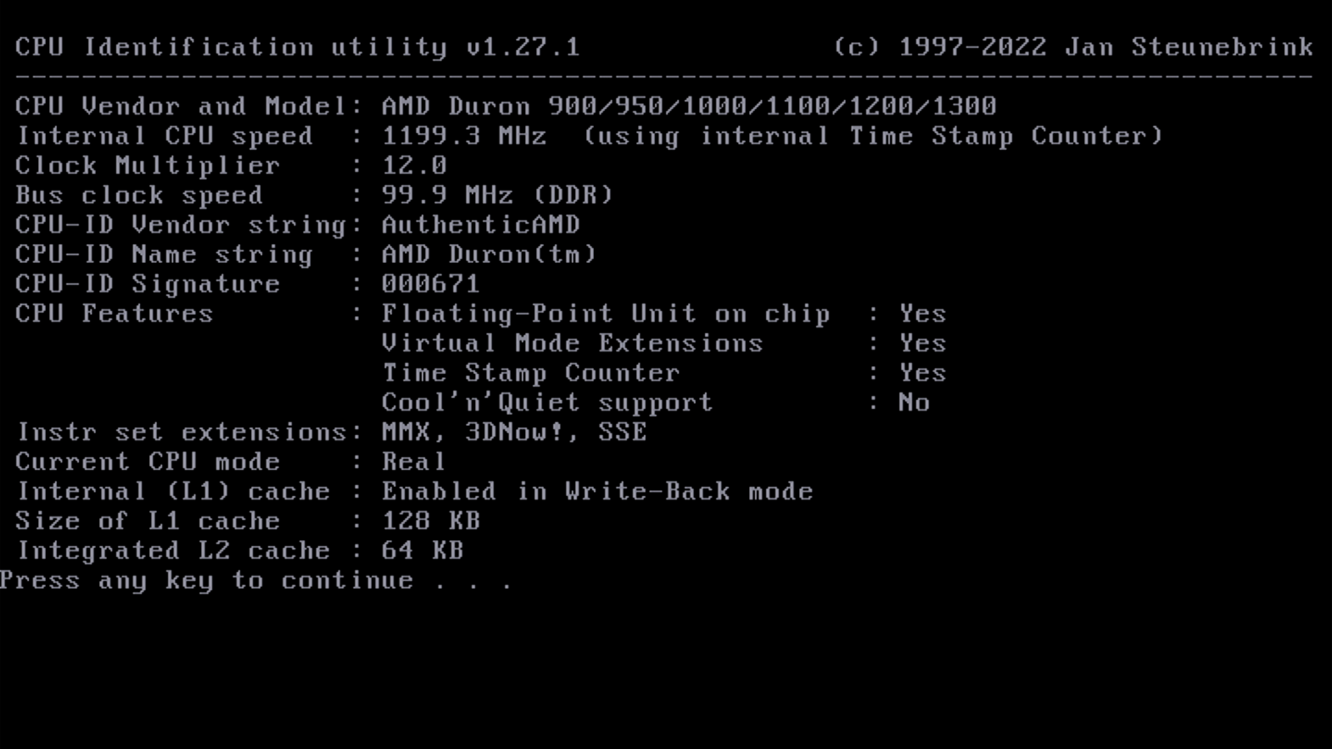
However, it did boot 🙂 and I had a mini reveal party – the CPU! An AMD Duron at 1200Mhz:
The Details
The Re-Paste
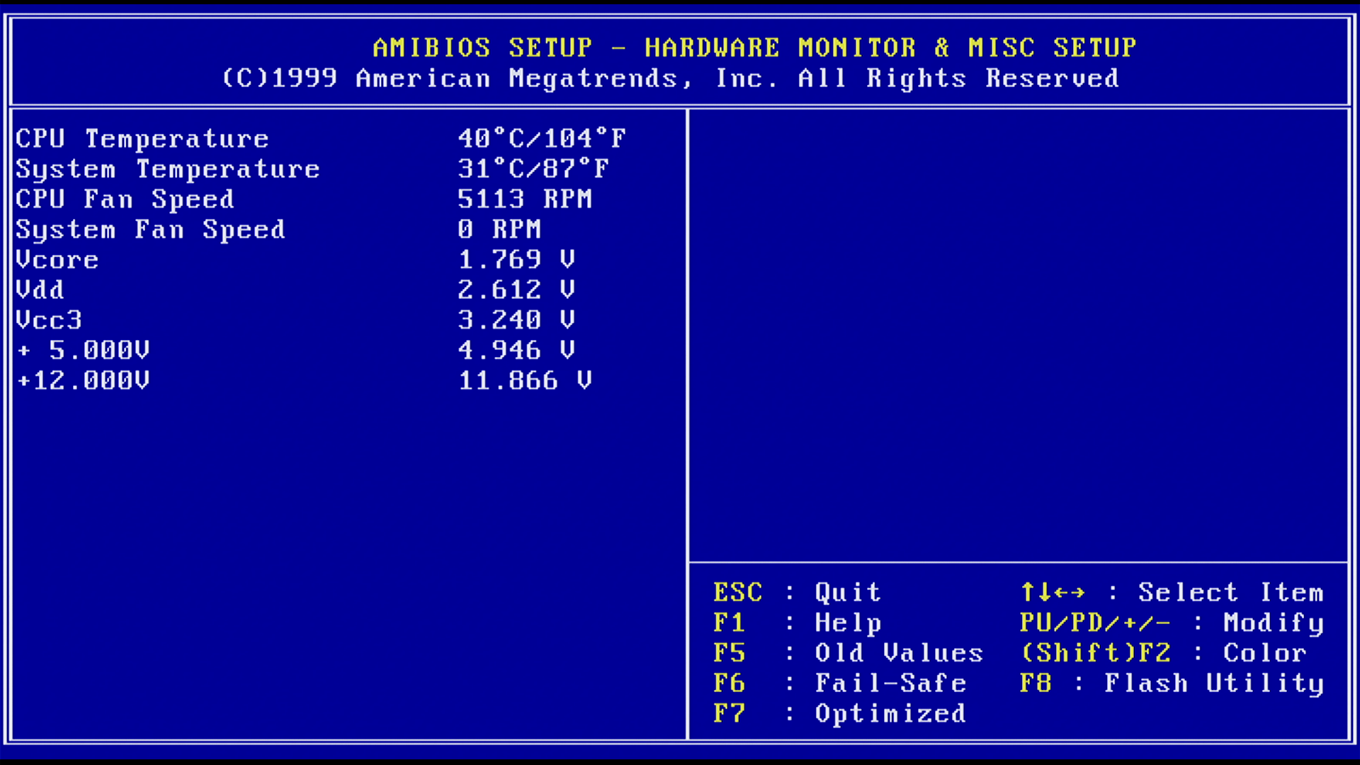
The annoying thing with the motherboard is that the CPU fan runs at 5100 RPMs while the computer is idle. I thought they already had PWM control by this time – the fan does have the 3rd control pin. The motherboard drives it at 5100 RPMs, even if the CPU is sitting at 49C in BIOS. Maybe is normal and I forgot, or maybe the PWM drive is faulty ?
Nostalgia came back – the era of noisy PCs and finger braking heat-sink clips.
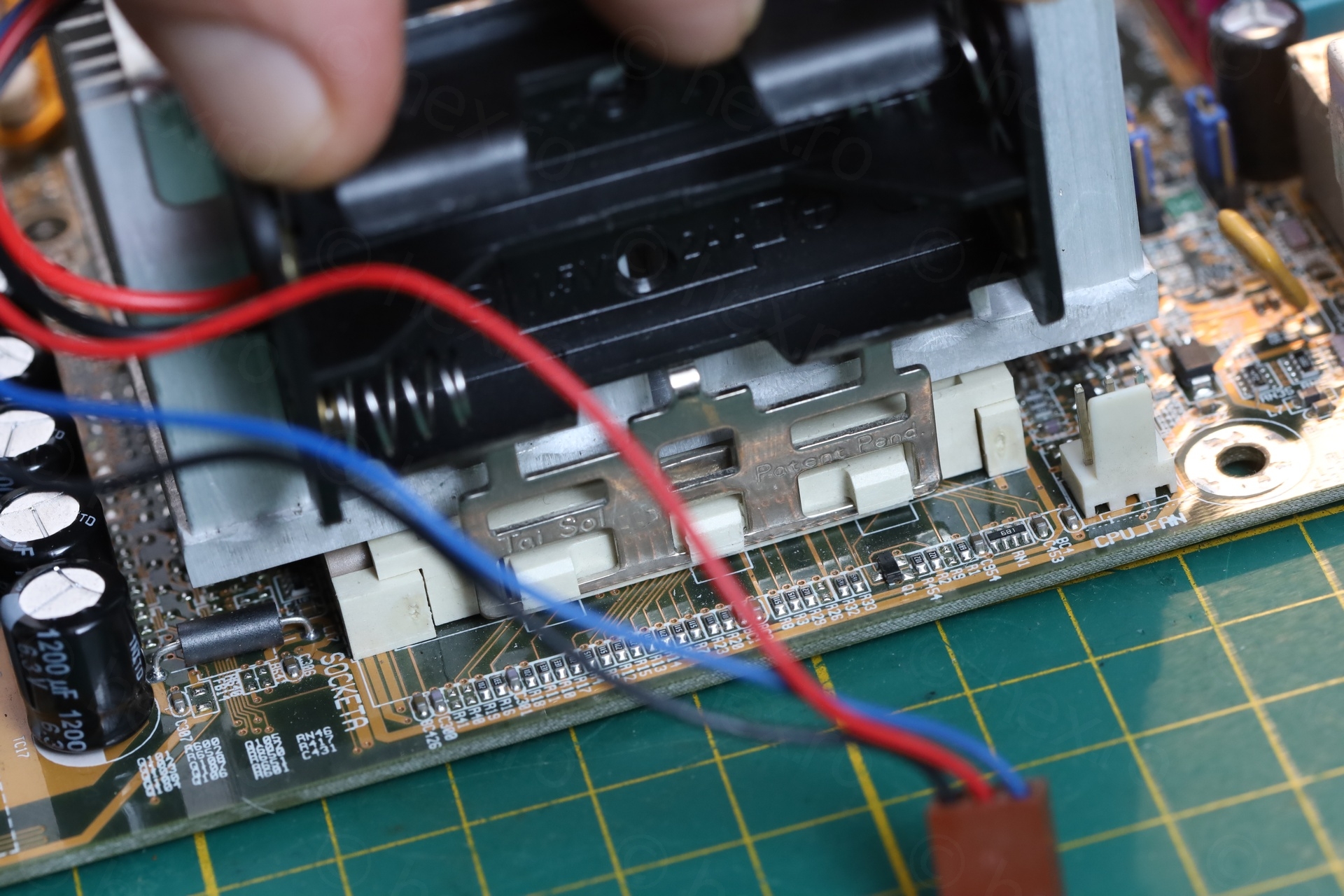
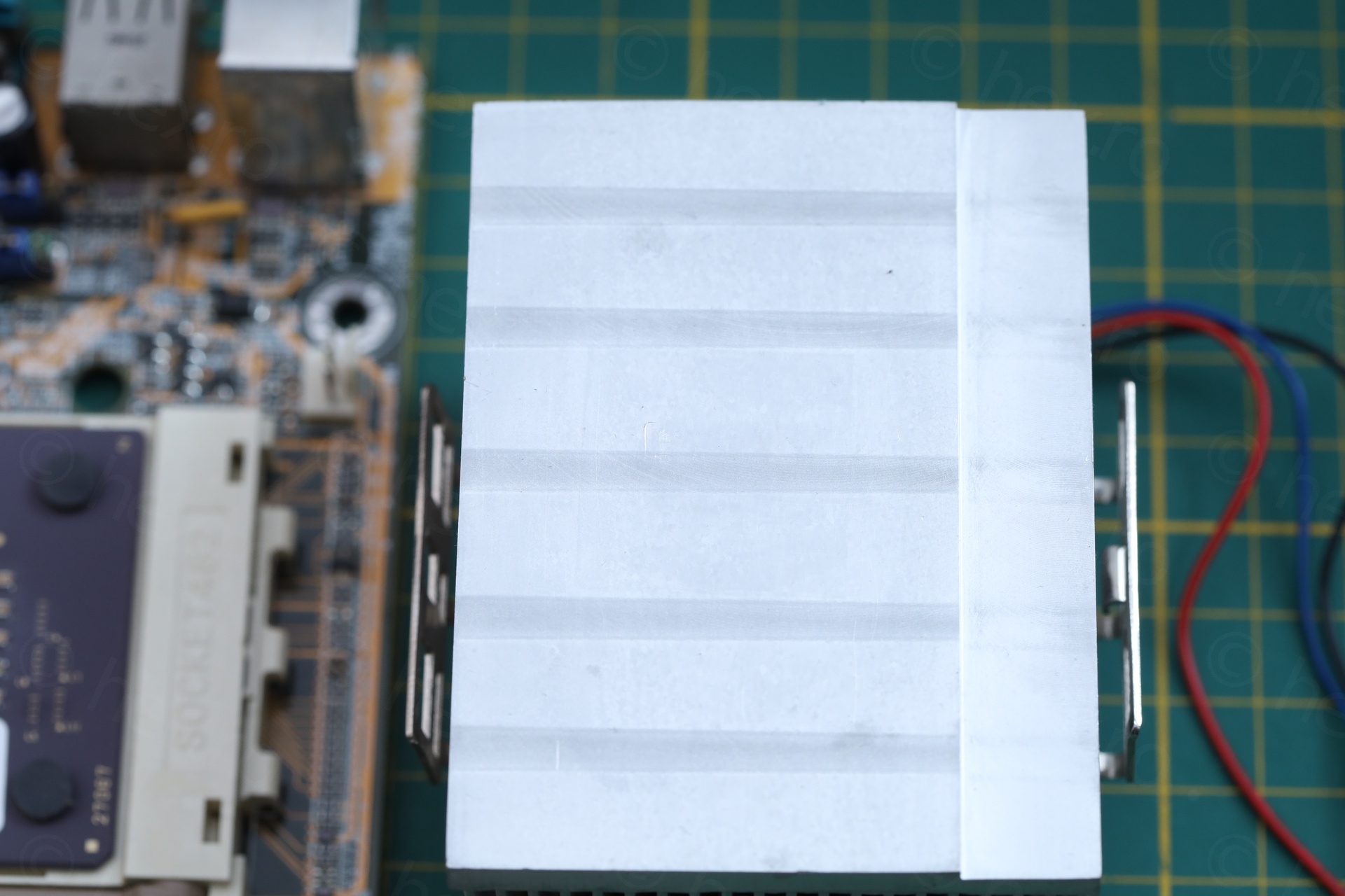
I used a 2xAA battery holder to put a lot of down pressure on the clip. The clip is so rigid that a slight imbalance will not allow releasing it over the 3 plastic hooks at the same time. While applying a lot of pressure for the metal to reach the bottom, you have to gently use a screwdriver to maneuver it around the plastic hooks – mindful of all the small components on the side of the motherboard:
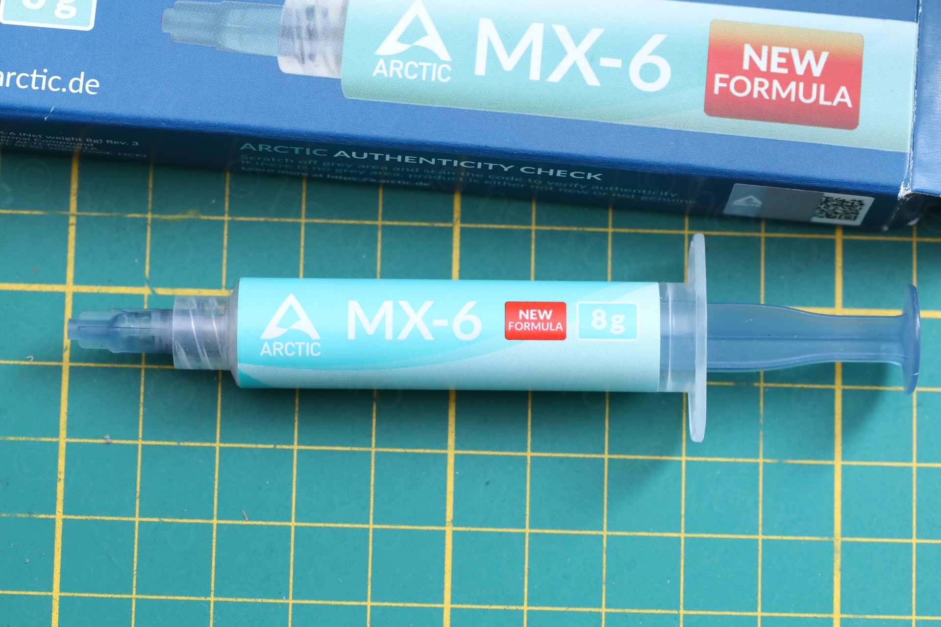
The paste was the original one. It was so hard, I had to use a Label Peeler to get it to melt first, followed by Isopropyl Alcohol to clean all the oil. Decided to use Arctic MX-6 Thermal paste as replacement. It is very viscous and hard to spread thin – for sure I put too much of it.
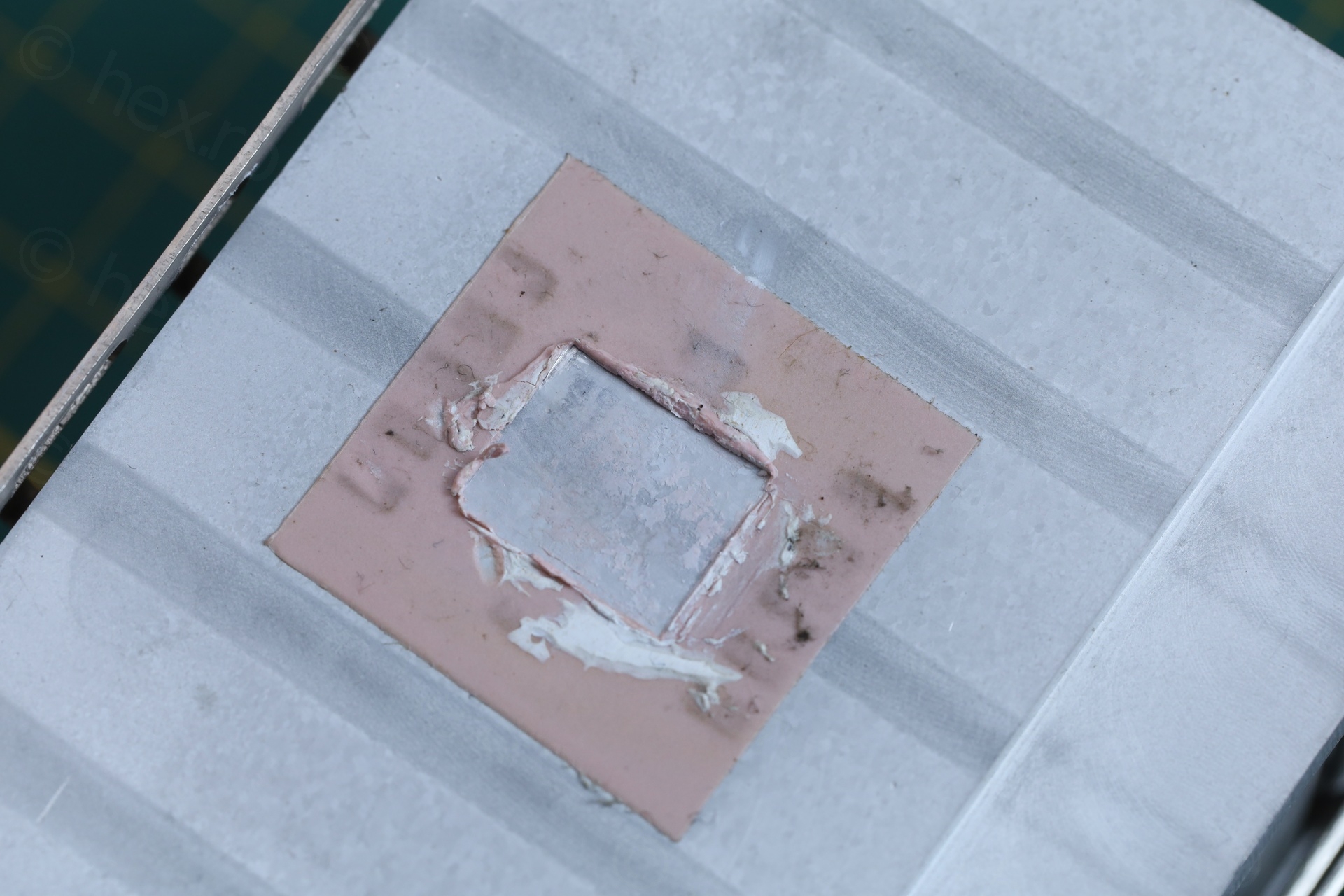
I realized I put too much as… just after after the re-paste, the BIOS was showing the same 49C ? I was confused – was the original paste so good after all these years ? A week after I found some time to stress test on the board. I discovered that CPU was at 40C just sitting in there BIOS. Most likely, it took a while for the viscous paste to be spread even thinner by the heat-sink pressure and it settled. 9C win.
This didn’t quiet the fan though, it is still happily running at 5100RPMs. Technological advancement is impressive in the last 25 years – modern fans are inaudible / off when computers idle.
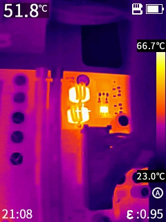
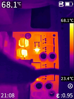
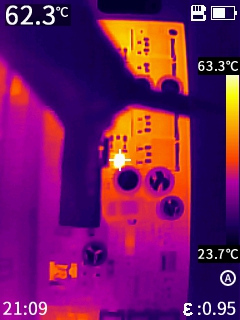
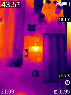
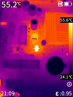
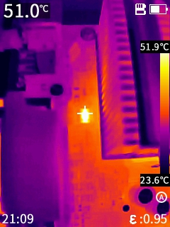
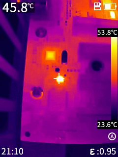
The Thermal Footprint
The boars is not very hot, except the two inductors plus two HIP6601ACB MOSFETs in the top right corner:
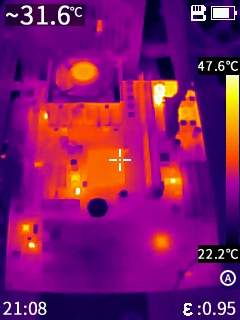
Close ups:
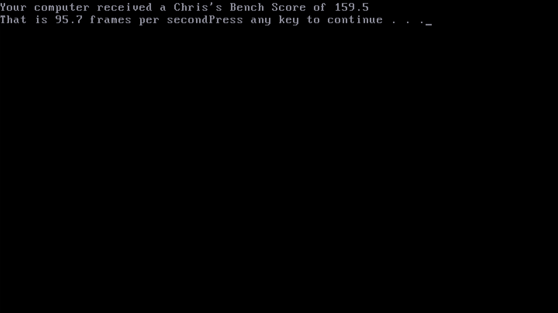
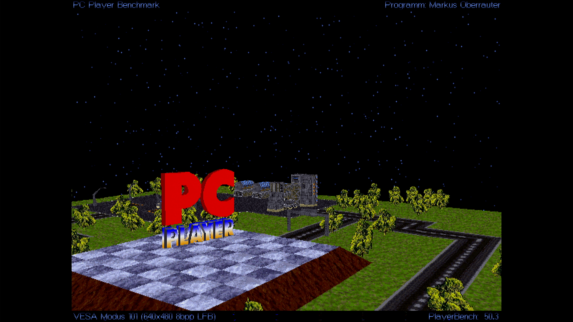
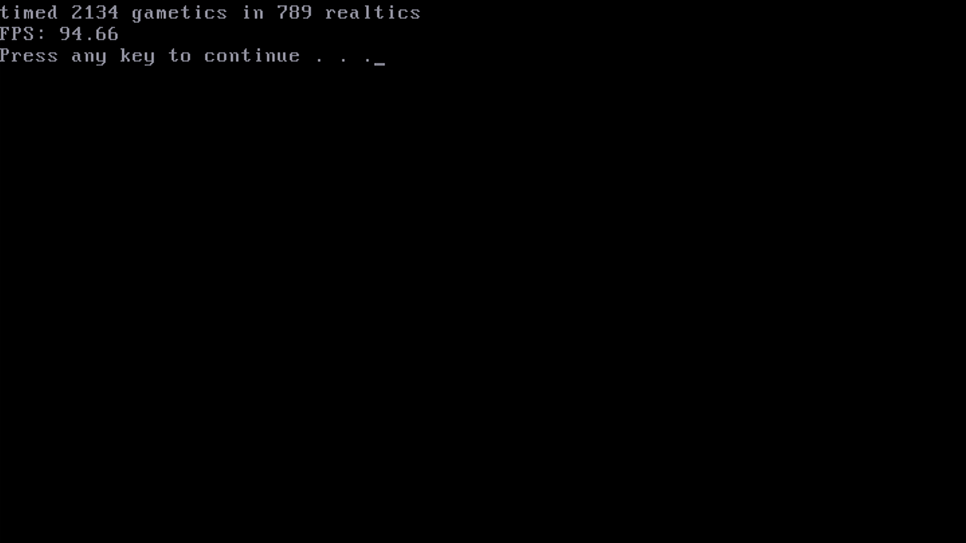
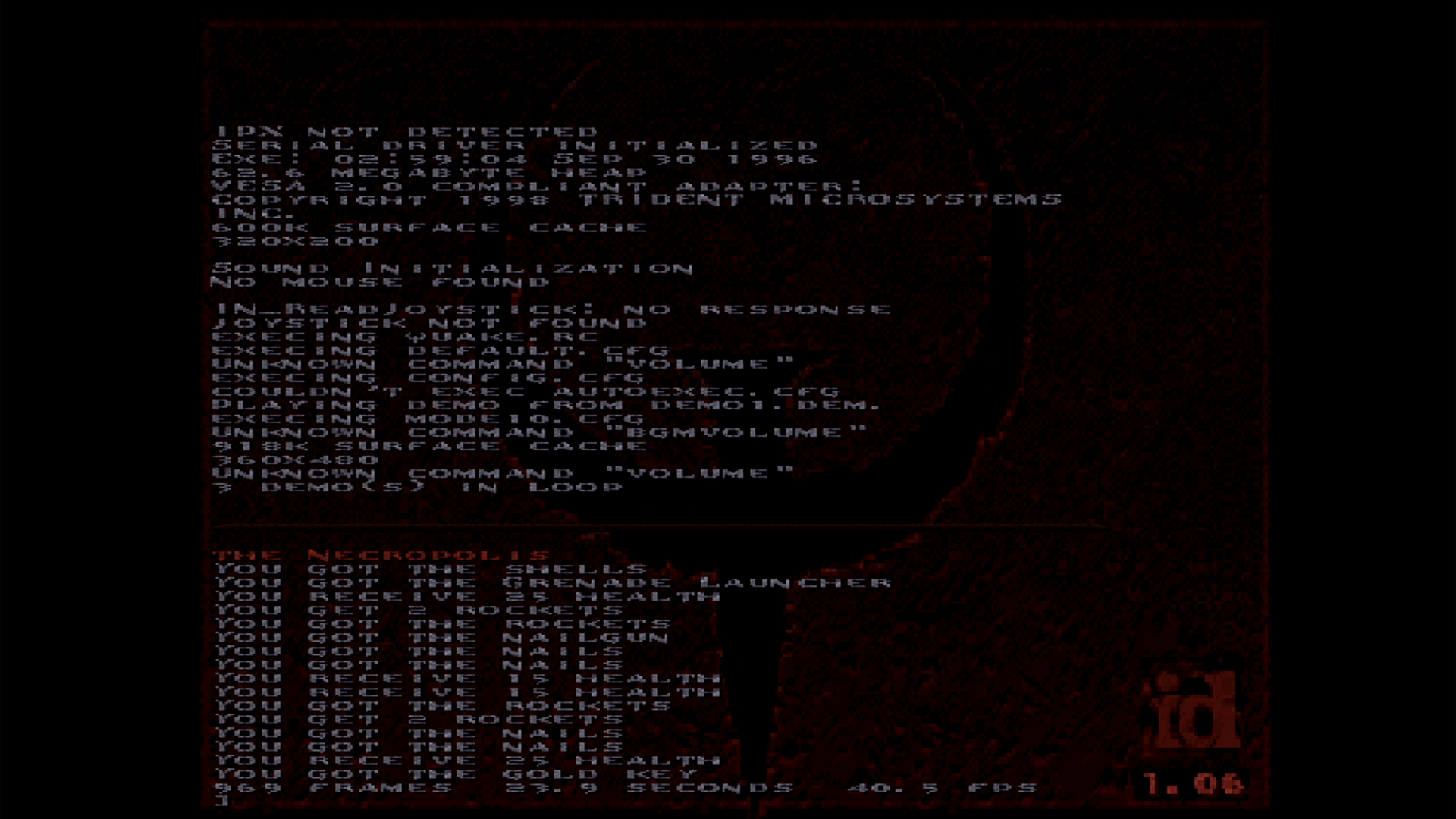
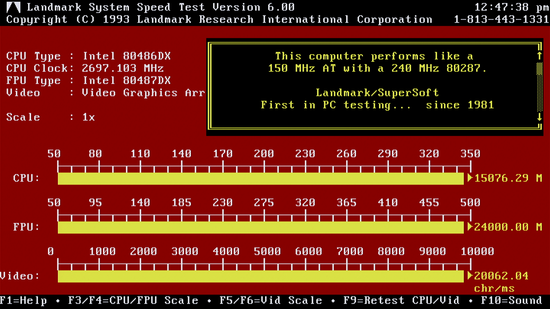
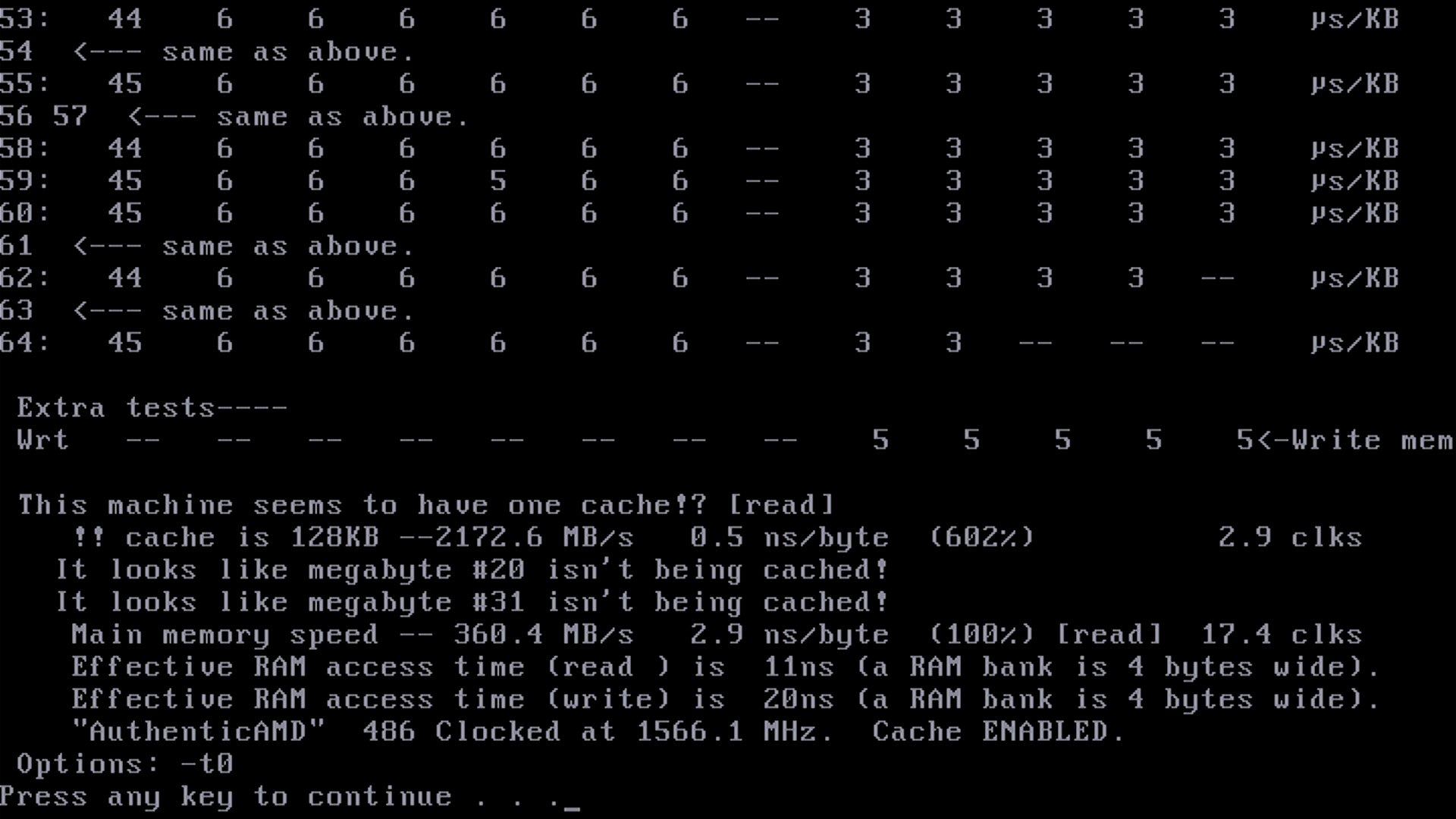
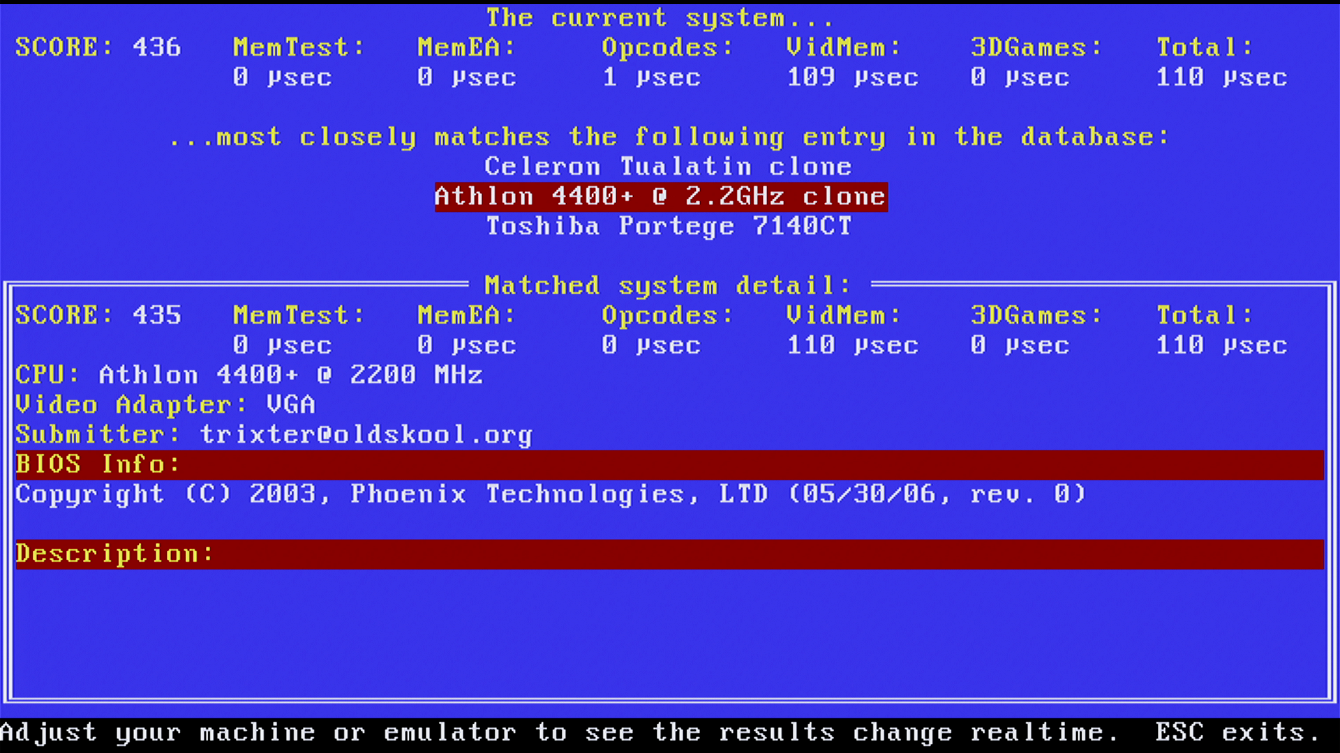
The Stress-Tests
I used FreeDOS + DosBench suite to gather some statistics / performance metrics from the system. The manual indicates that the Video card is a “Trident Blade 3D Graphics Controller in VT8361”:

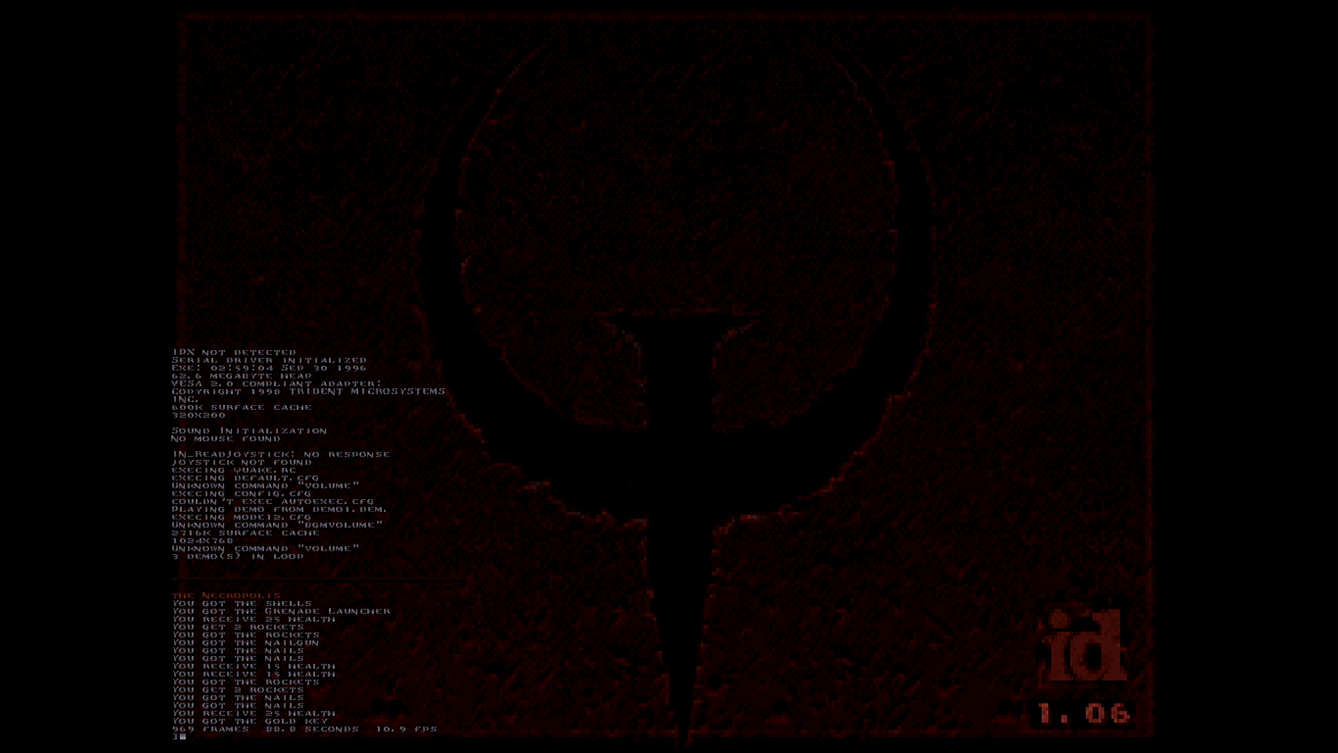
Although I did try the “Load Optimized Defaults” and system behaves faster according to the tests – some tests did not benefit much and the system was a lot more unstable (hard freeze, sometimes just after the boot screen).
Conclusions
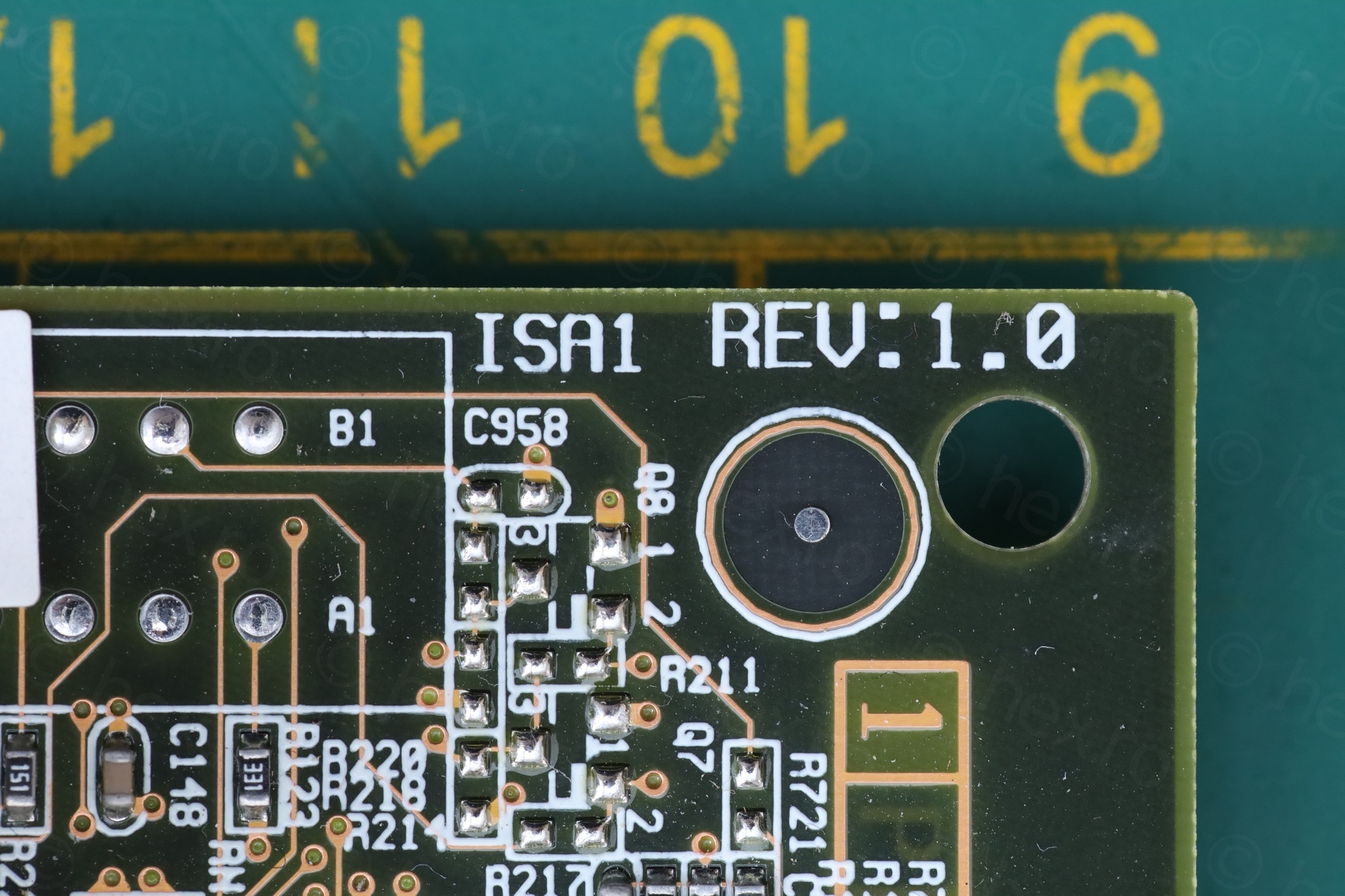
There is an ISA Slot, but … I have other motherboards with ISA Slot and it didn’t make sense for me to try to max it out. I should order one though, just in case.
I have also resisted the urge to upgrade the memory. If I would use the board, it would make sense to have more RAM. I did it in the past with other boards that ended up not being used – and it was just wasted money. The goal was repairing it.
Thus, happy that the board still works fine after all these years. Hats off to Gigabyte for having the motherboard page still up after all these years.
Leave a Reply