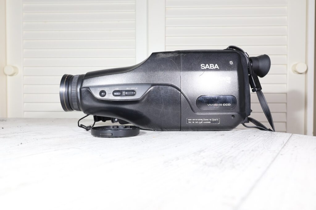
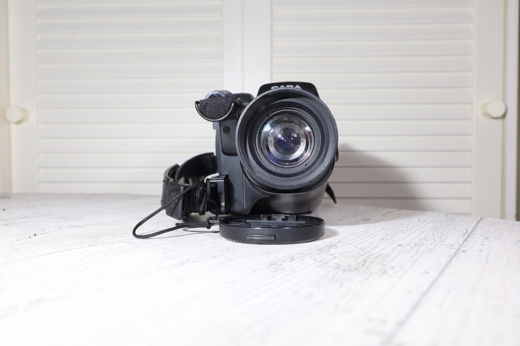
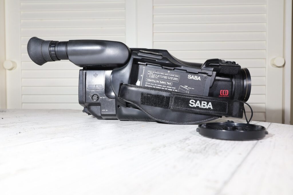
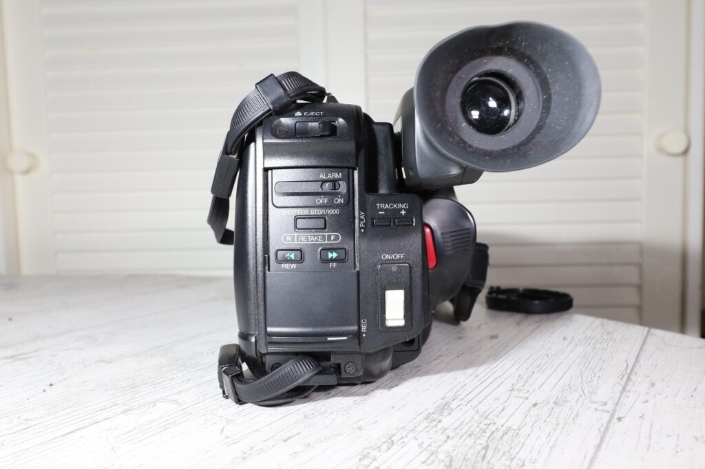
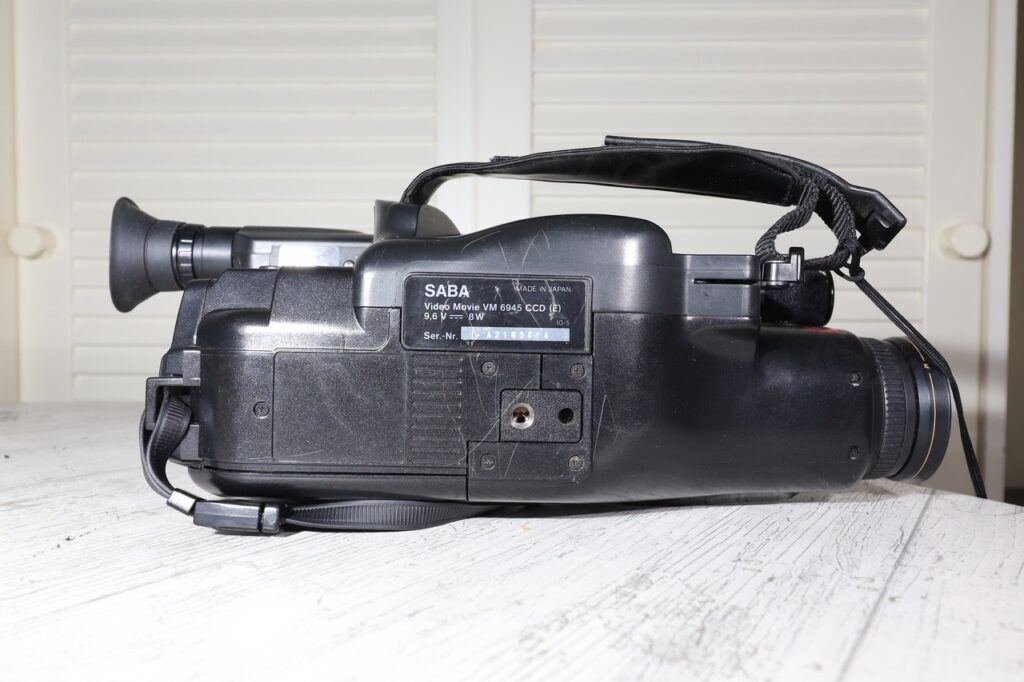
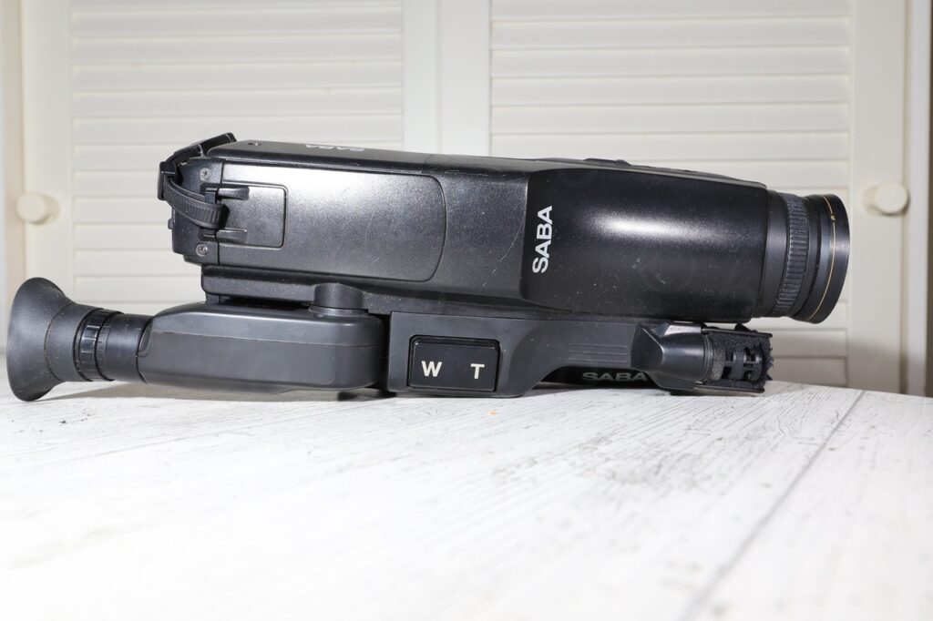
Found this CRT inside a SABA VM6945 CCD camcorder that I got at a flea market.
Camera
The camera itself was in good looking condition, however, it only partially worked when powered with external supply. Eject worked, the CRT would come on but stay gray – and nothing else.
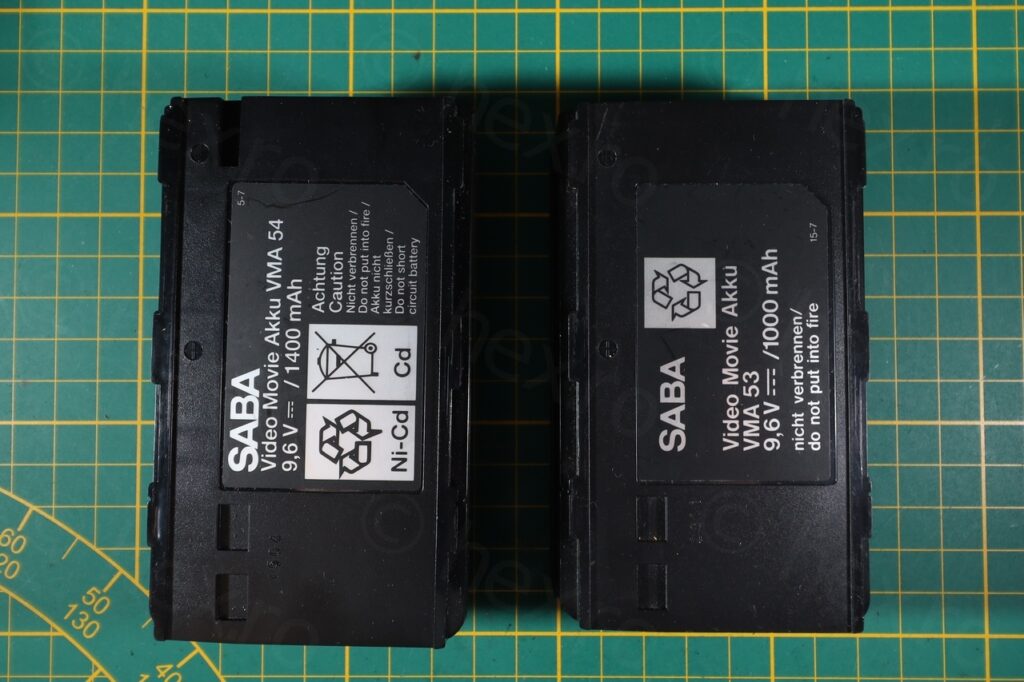
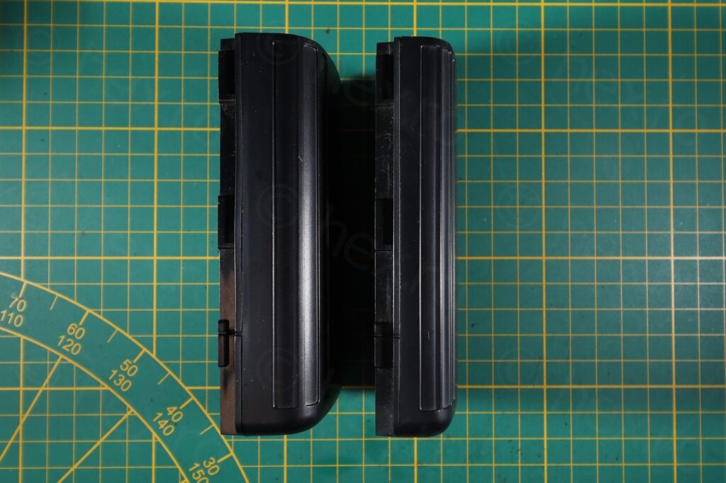
Camera was sold with two batteries, but I do not try to charge a 30+ years old batteries.
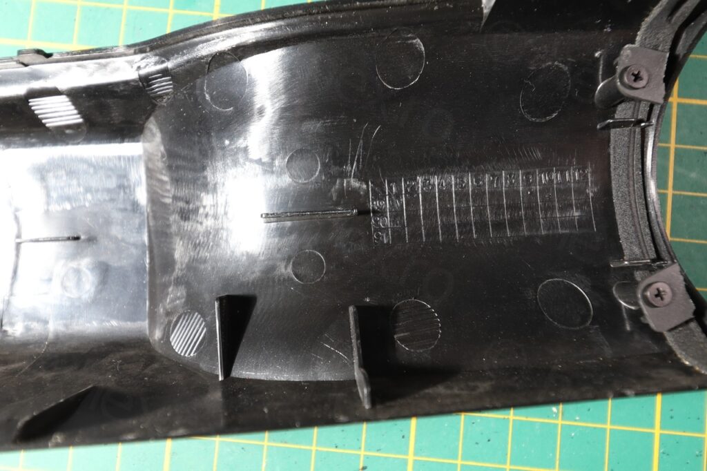
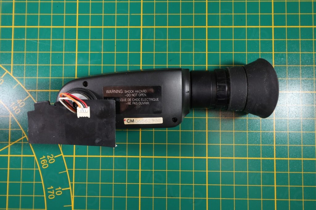
Opening the camera was rather easy and the first good sign is that the EVF unit is attached to the motherboard with normal 4 wire cable:
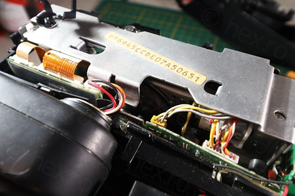
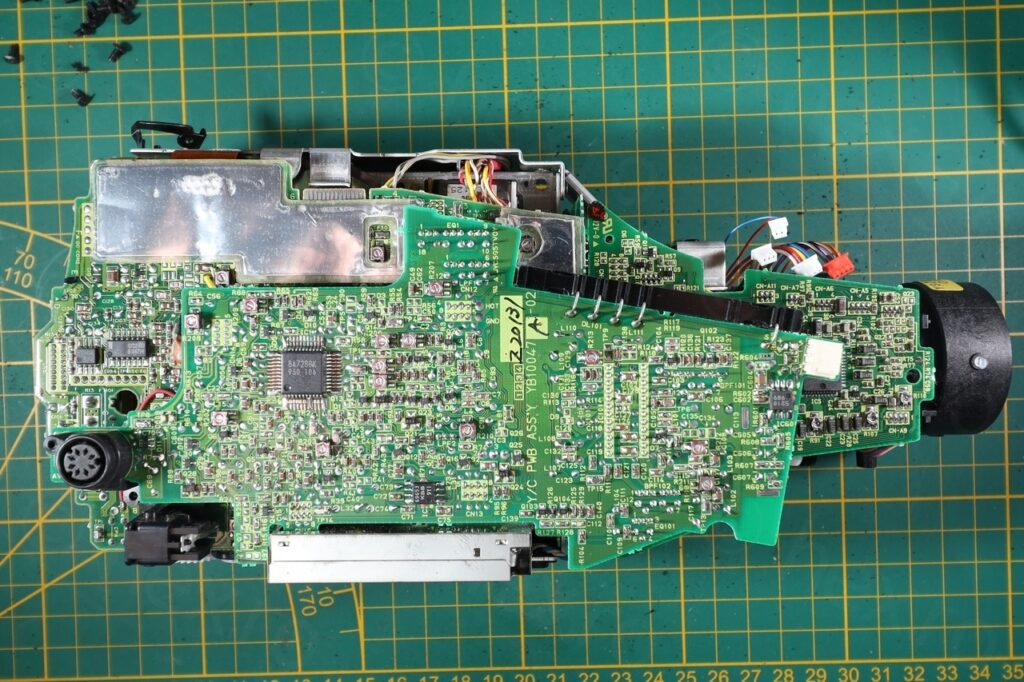
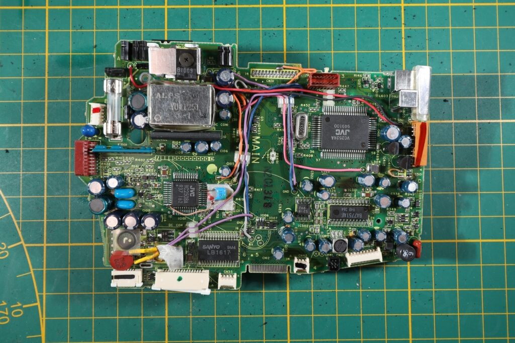
Date codes on various parts indicate end of 1989, beginning of 1990 as production year of the components:
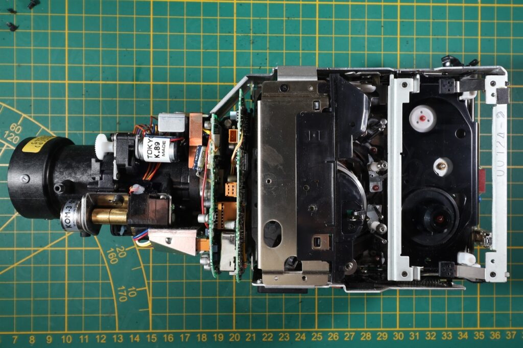
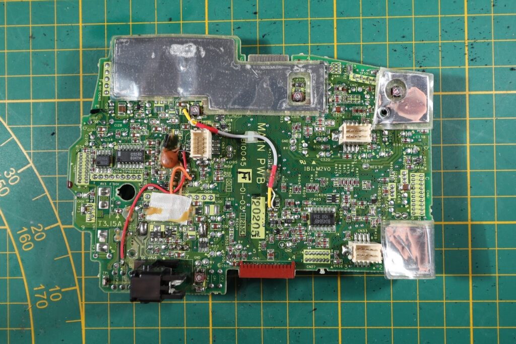
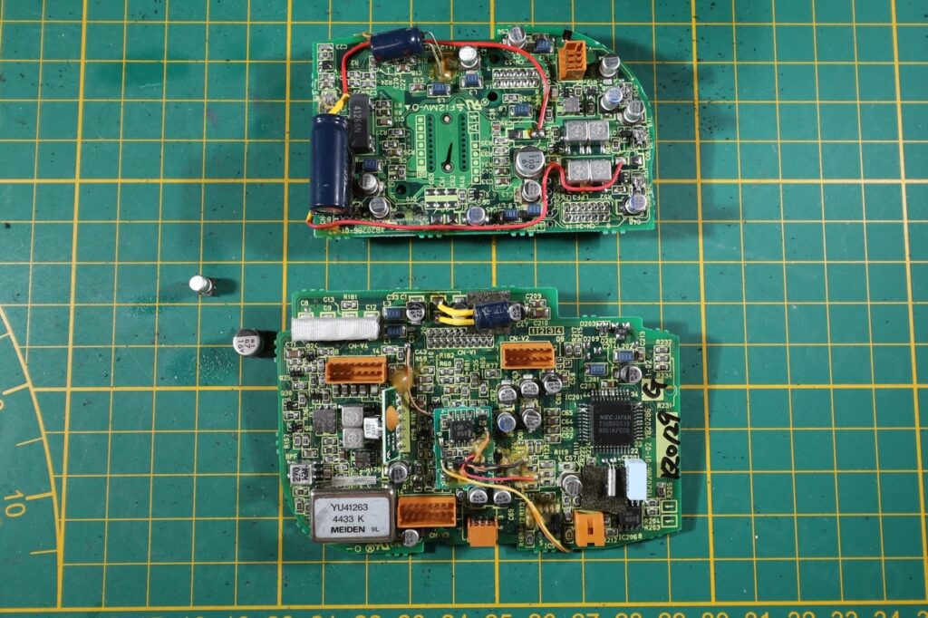
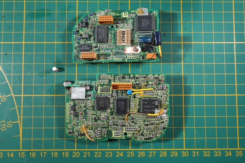
The internal construction was nice, a sandwich of boards, but I did find many bodges. In one of the photos you can see some capacitors even fell out just from the pressure of prying apart the boards – this explains why the camera only partially worked:
Electronic View Finder
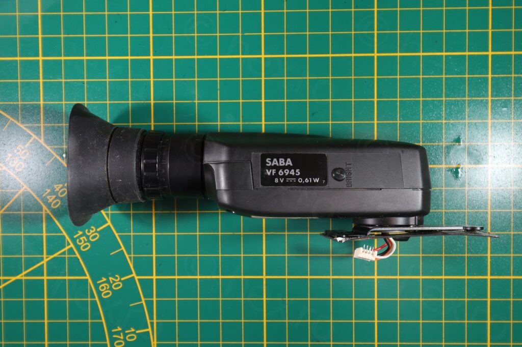
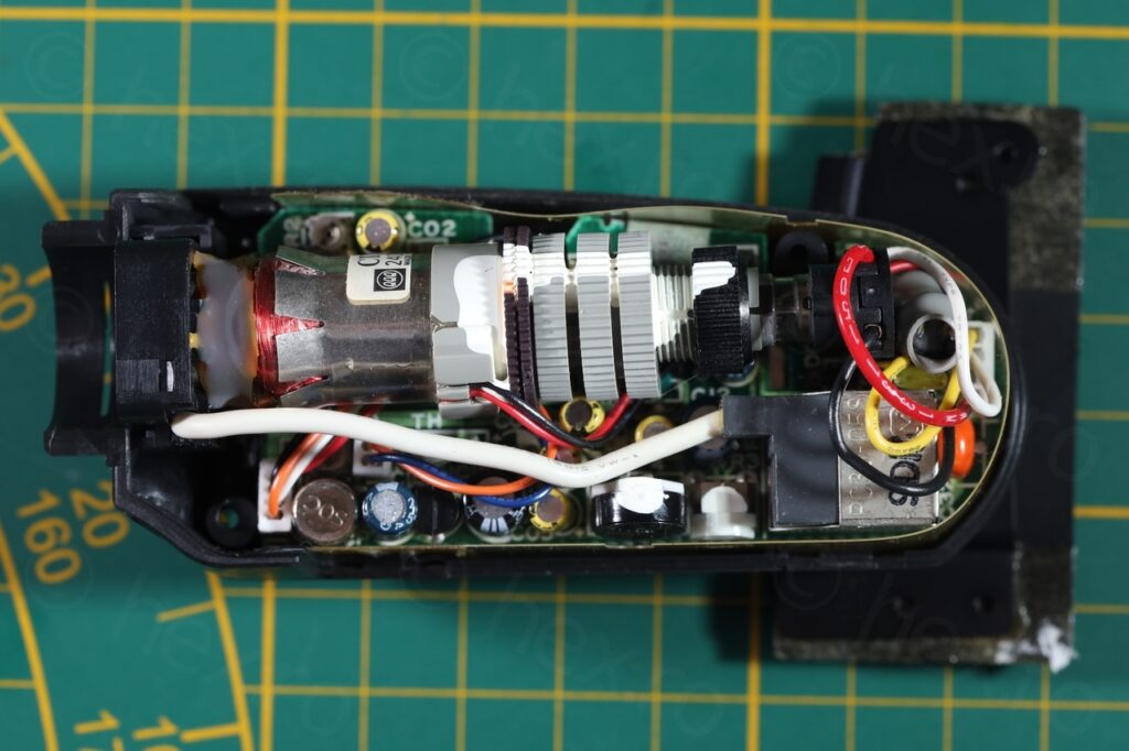
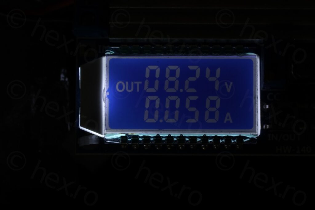
Since the CRT was briefly turning on when external power supply was applied to the camera, I had hopes it would work. I proceeded to open up the EVF enclosure. Voltage required for the module is 8V according to the sticker on the side. Inside, the electronics are arranged in a ‘breathable’ space, nothing too crammed:
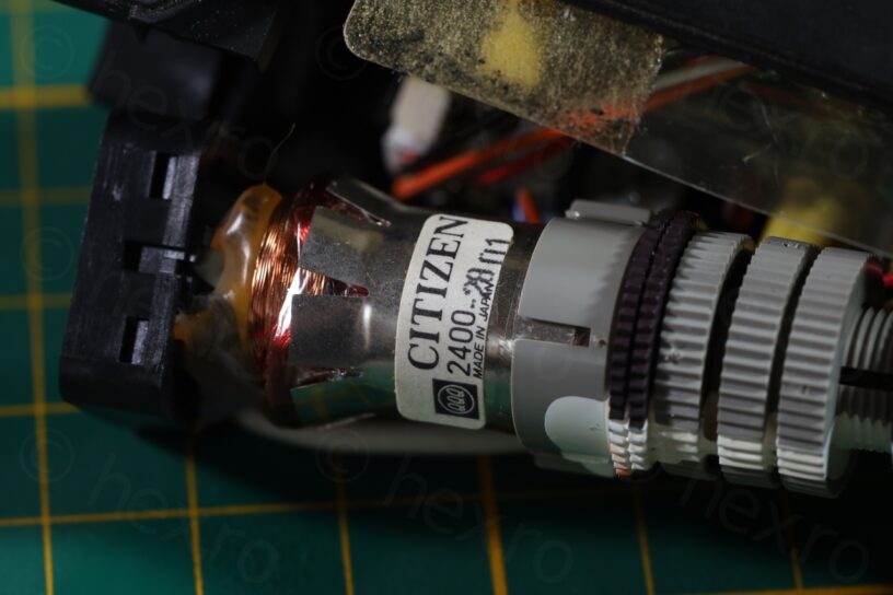
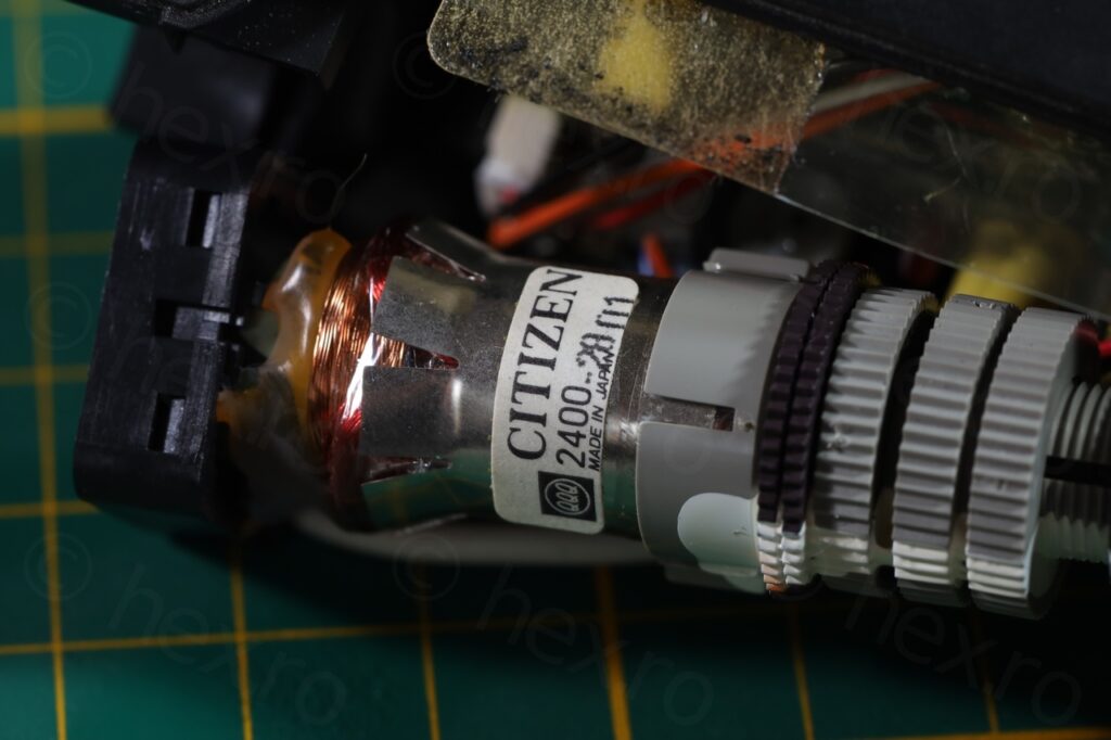
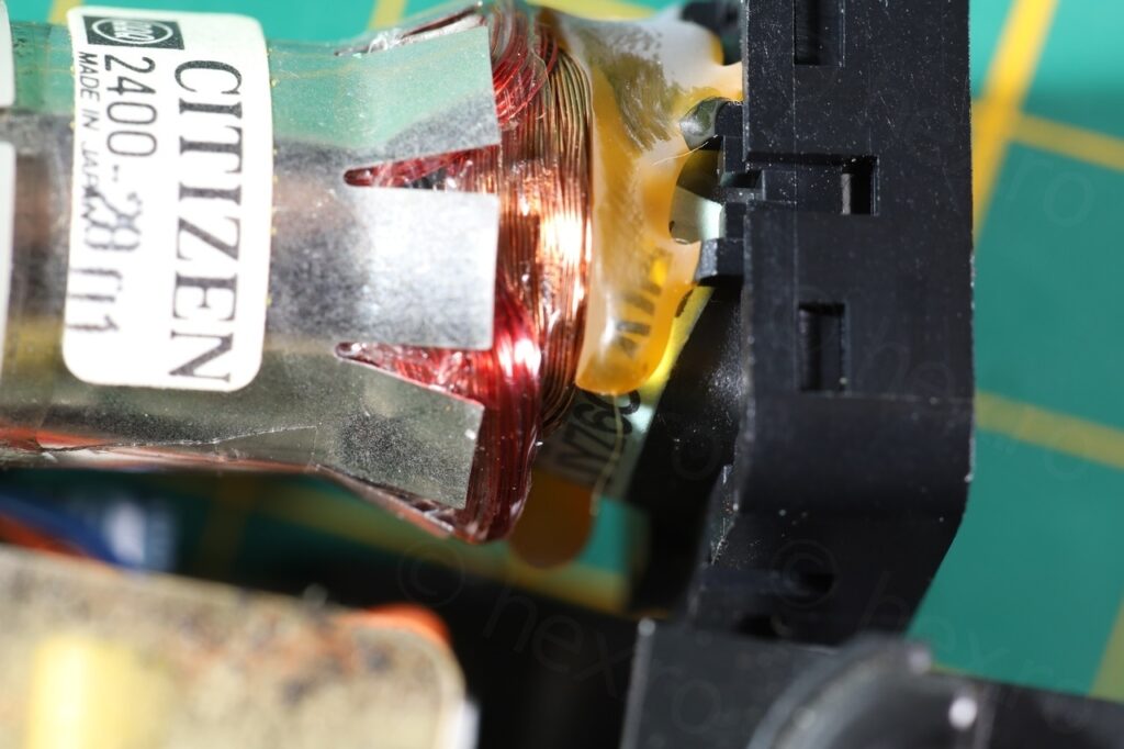
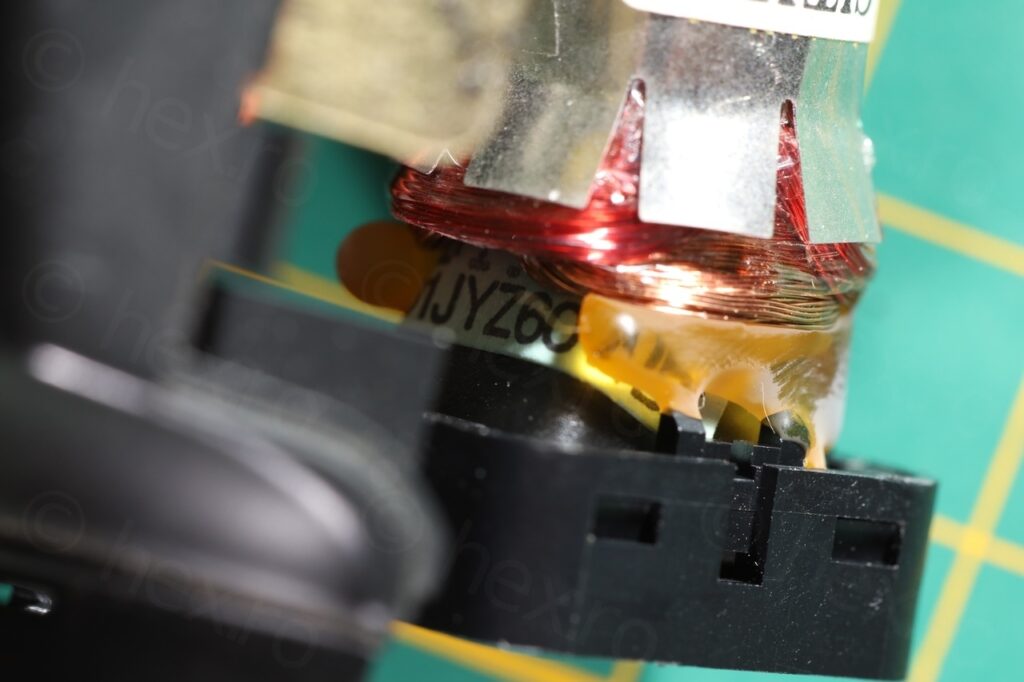
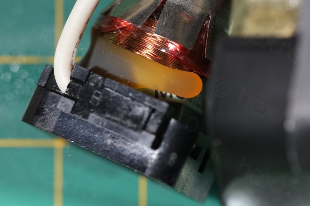
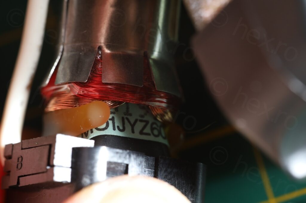
One of the confusing is what model the CRT itself is. I thought that the labels attached to the CRT have a correspondence with the other model number that sometimes is found on the glass tube. As you can see, the white label states CITIZEN 2400-28 01, however, the other blueish label states MO1JYZ70WB:
The trouble is that I encountered MO1JYZ60WB also on a CRT where the white label said CITIZEN 2400-10 (see here). Thus, the hypothesis that the two labels match does not hold. Another wierd thing is that in all the Citizen / Miyota CRTs, the second number is also stamped with the same font, but here, the white label says CITIZEN 2400- and the second number “28” is stamped differently. There’s also a “01” afterwards.
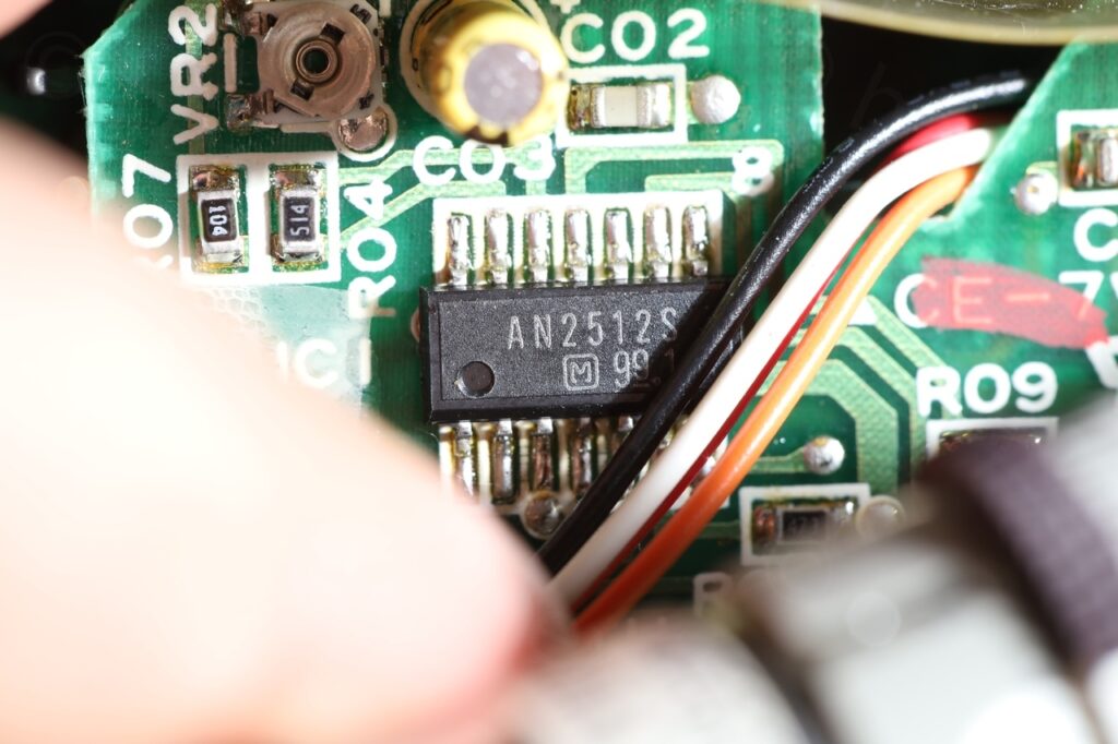
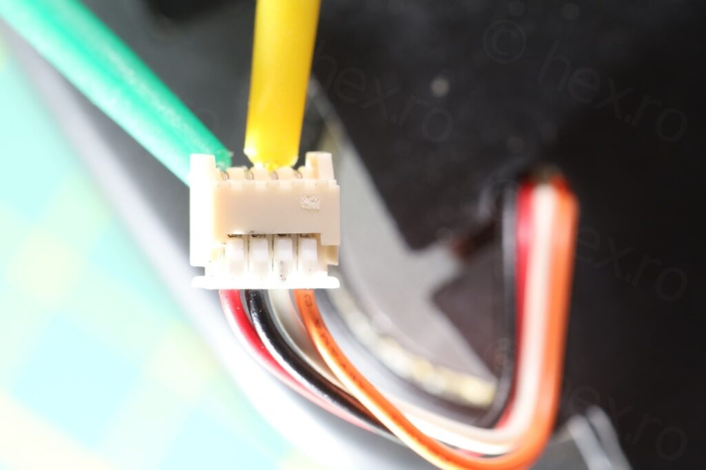
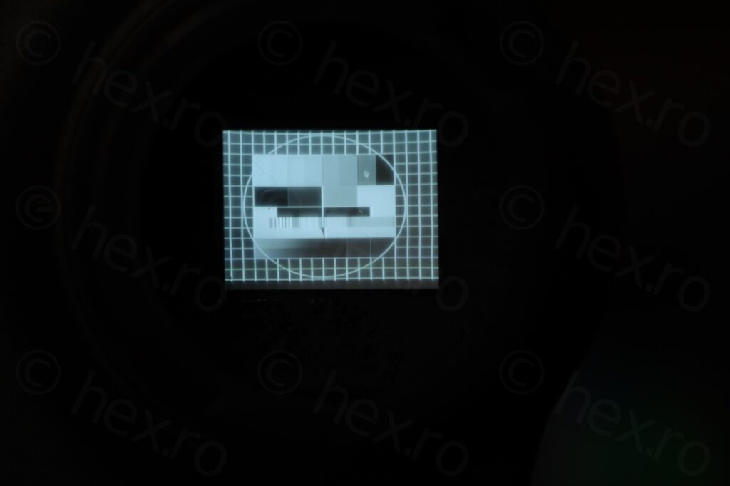
Having to leave aside the numbering, the CRT does work. Identifying the signal pins was easy. GND is the connected to the case of the Fly Back Transformer and is the black cable on the connector. The red cable on the connector shortly beeped when tested for continuity, meaning, it was most likely VCC, as these boards have a capacitor between VCC and GND which is empty, and continuity meter detects it as a short until capacitor charges. The Video IN is the white cable. I have also de-solder the connector from the motherboard, to make it easier to attach clamps to the EVF unit:
This was an easy dismantling, and I was lucky the EVF board worked given that some of the SMD electrolytic capacitors just fell off when I was handling the camera boards.


Leave a Reply