Found this mini CRT inside a Sony CCD-V800E camera that I have bought at a flea market. Camera was sold with the bag and some accessories which is always a plus. To me it means the owner took good care of it – enough so that it made its way through as is to the sellers.
Table of Contents
Camera bag and accessories
Few photos of the package, as sold. There was a lot of fine dust spread throughout which dirtied the work area while taking the photos.

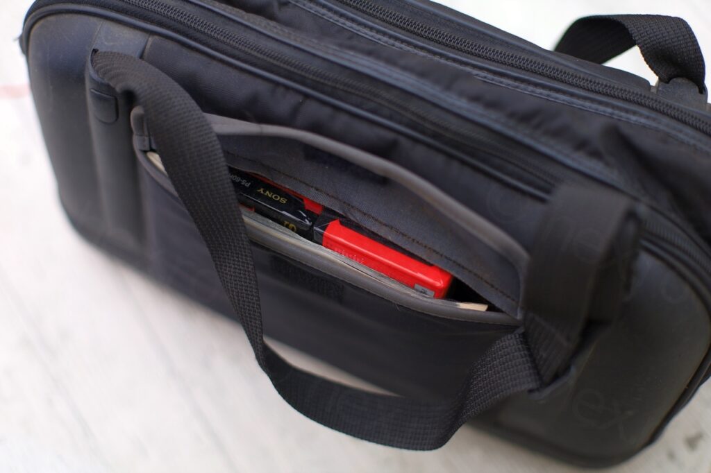
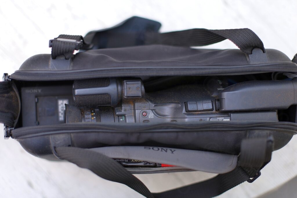
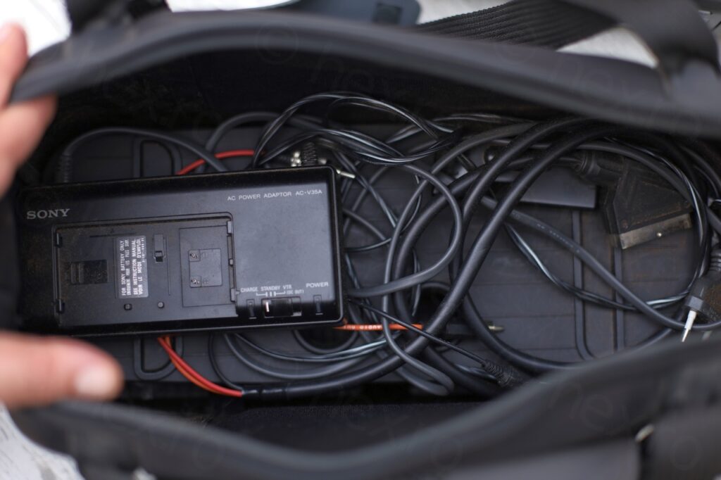
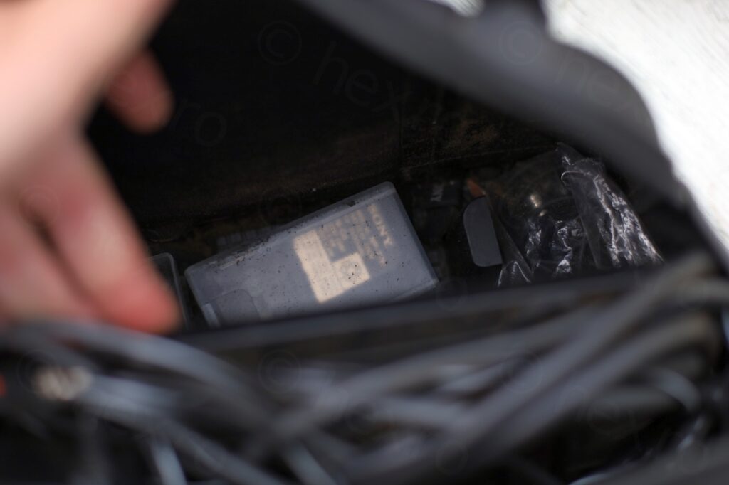
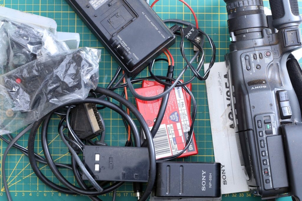
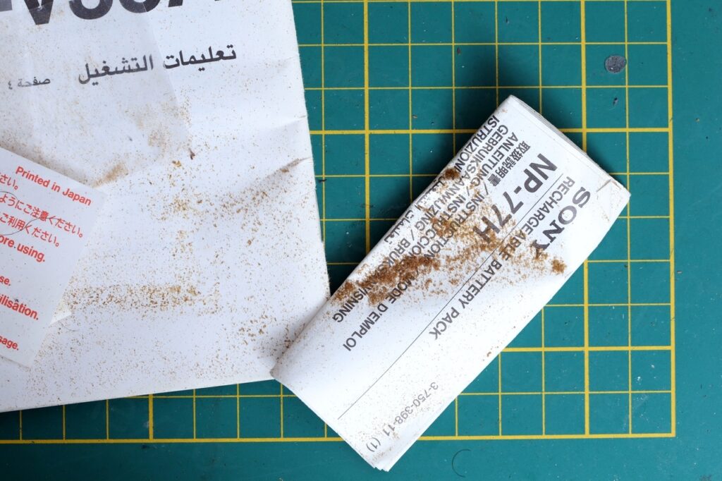
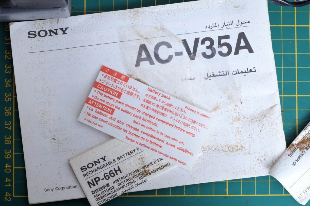
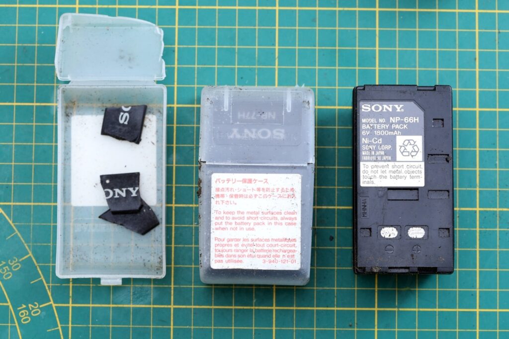
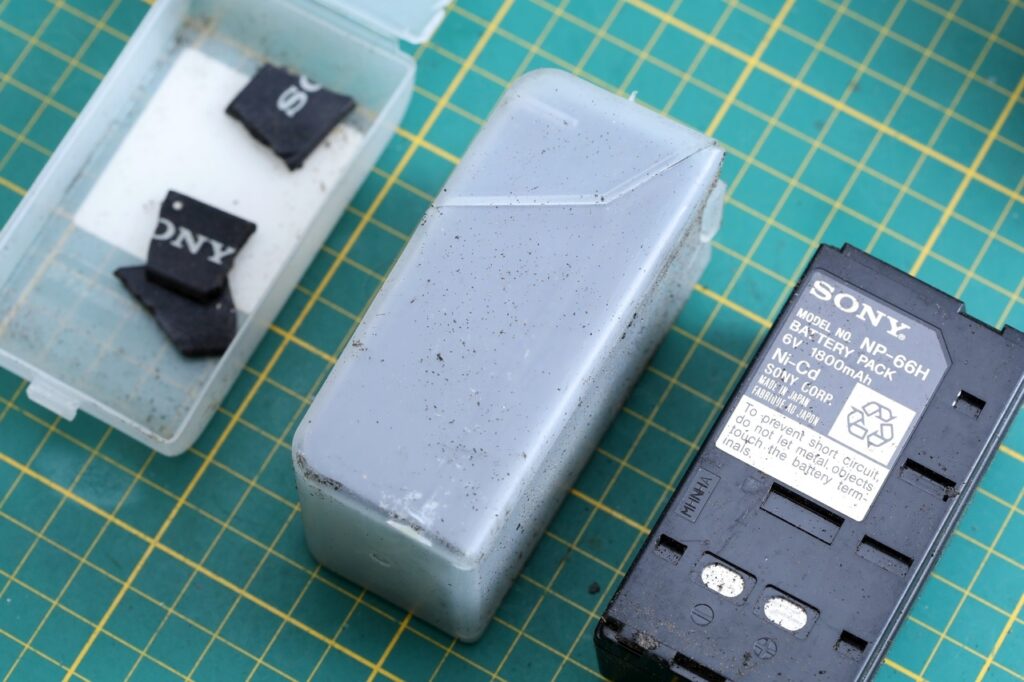

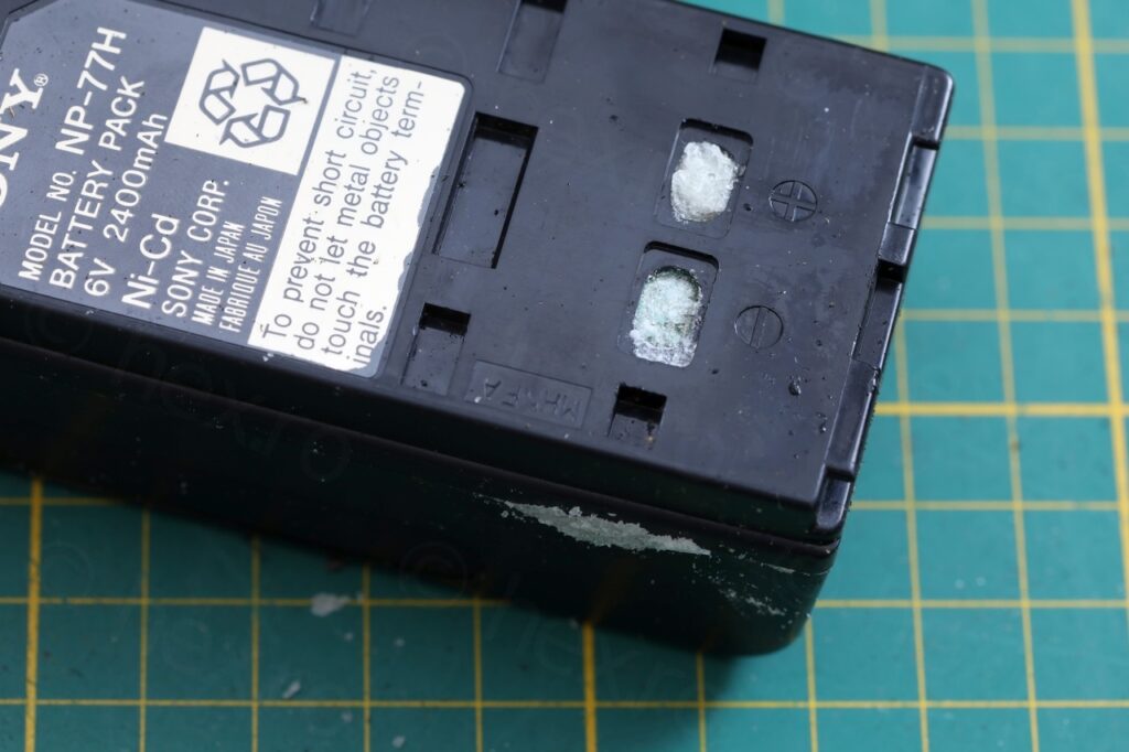
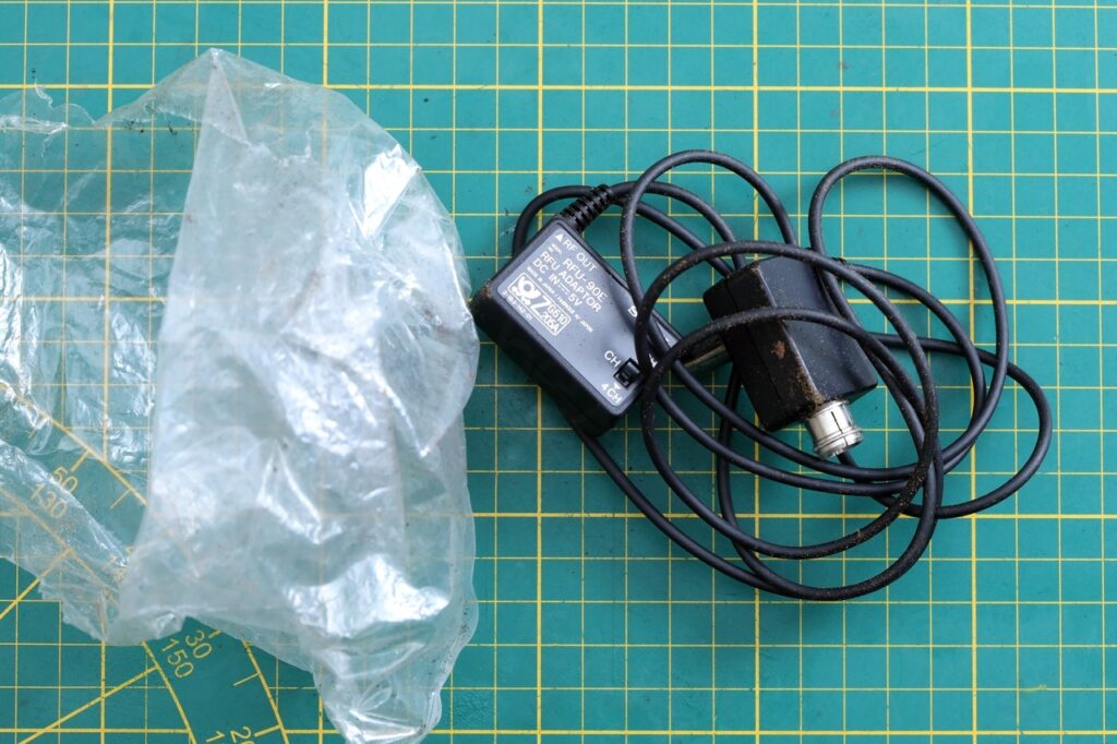

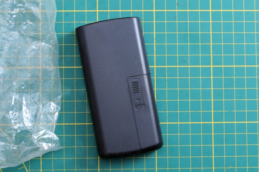
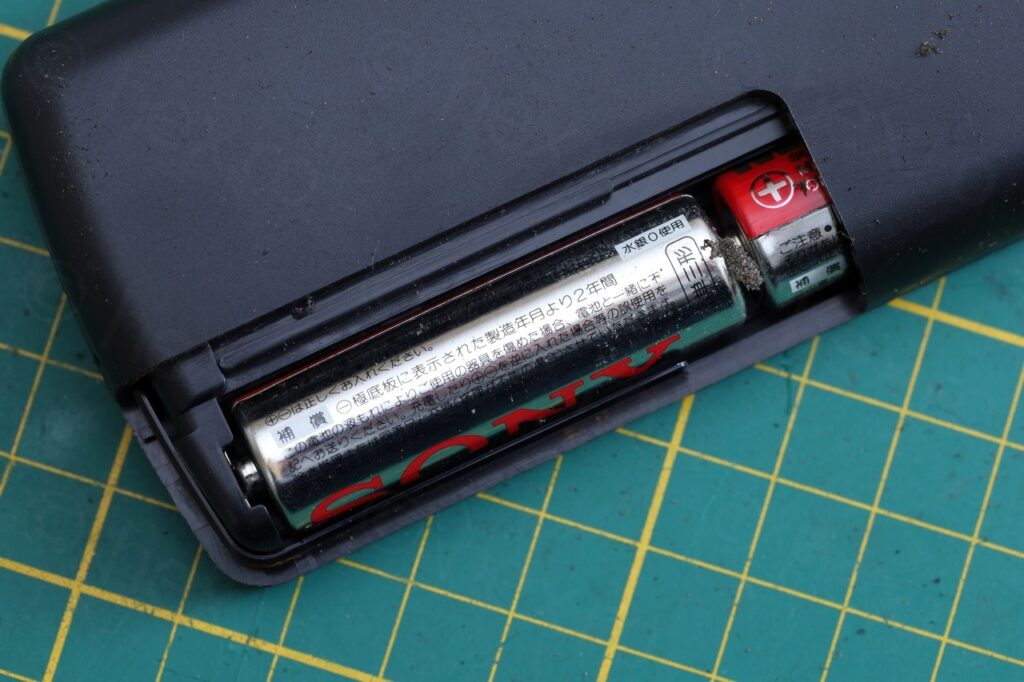
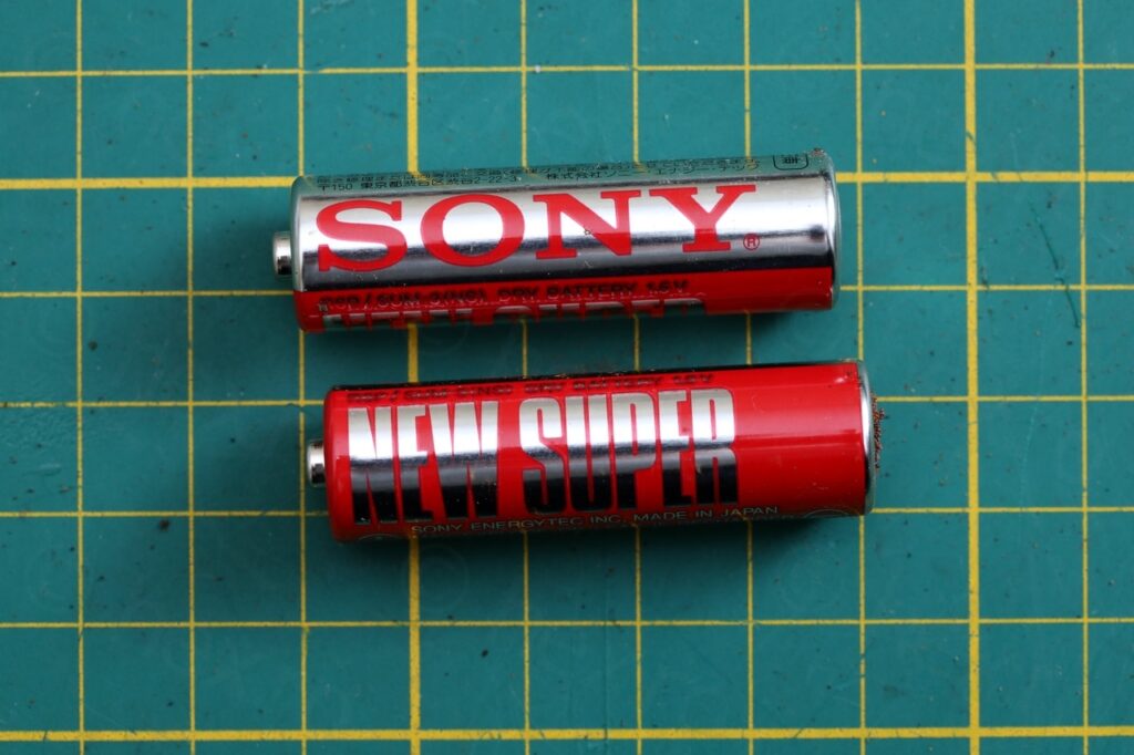
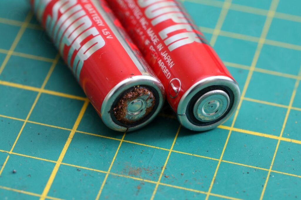
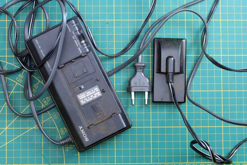
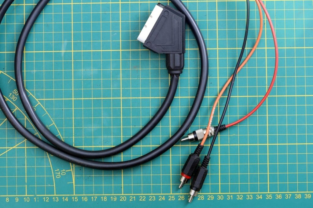
I had hopes to get the Electronic View Finder to work quickly – if something looks taken care of, somehow I have the expectation that is also “as new” inside, but …
Closer look at the camera
I took some photos of the camera itself:
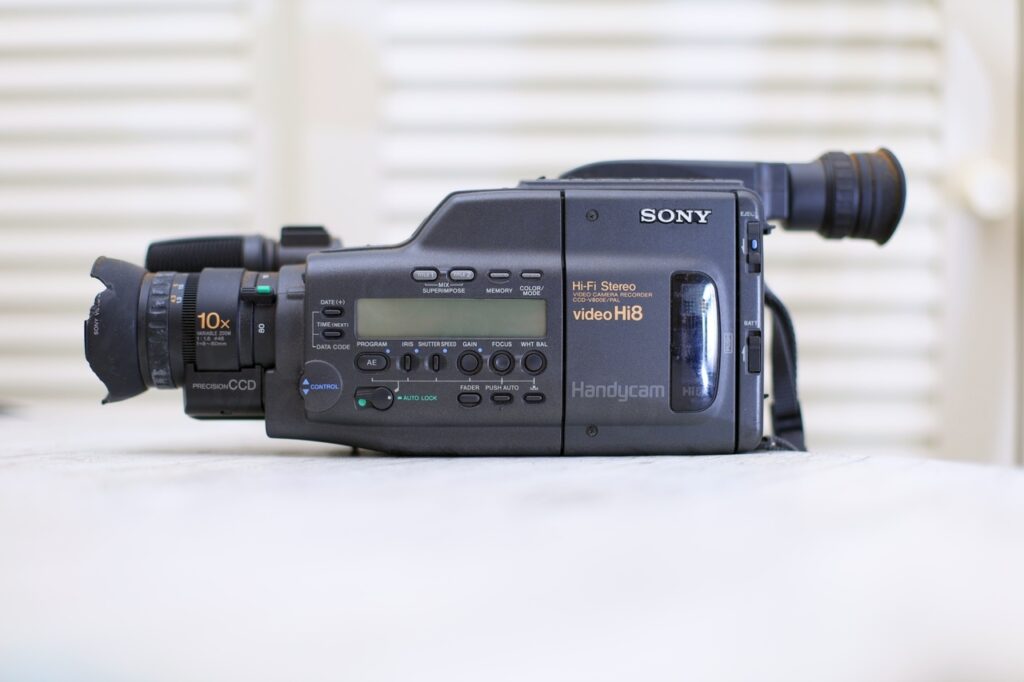
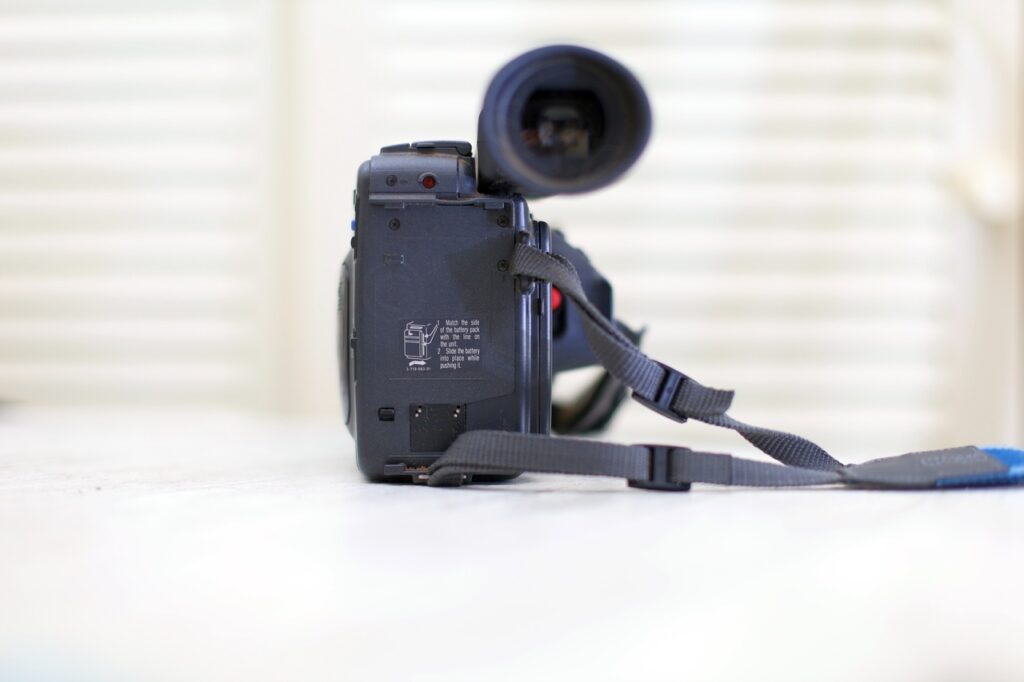

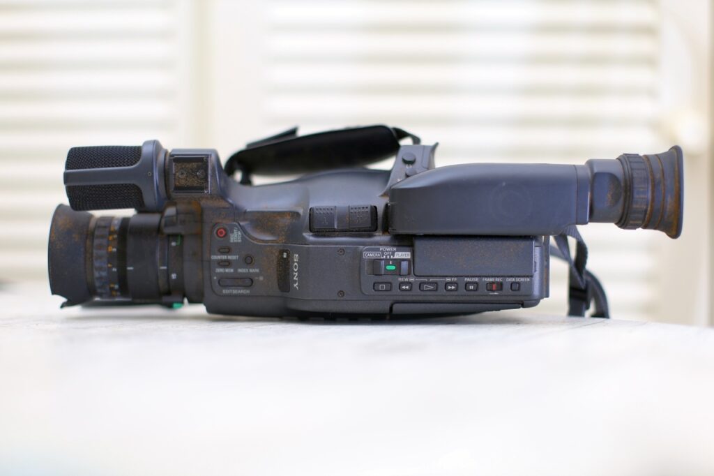
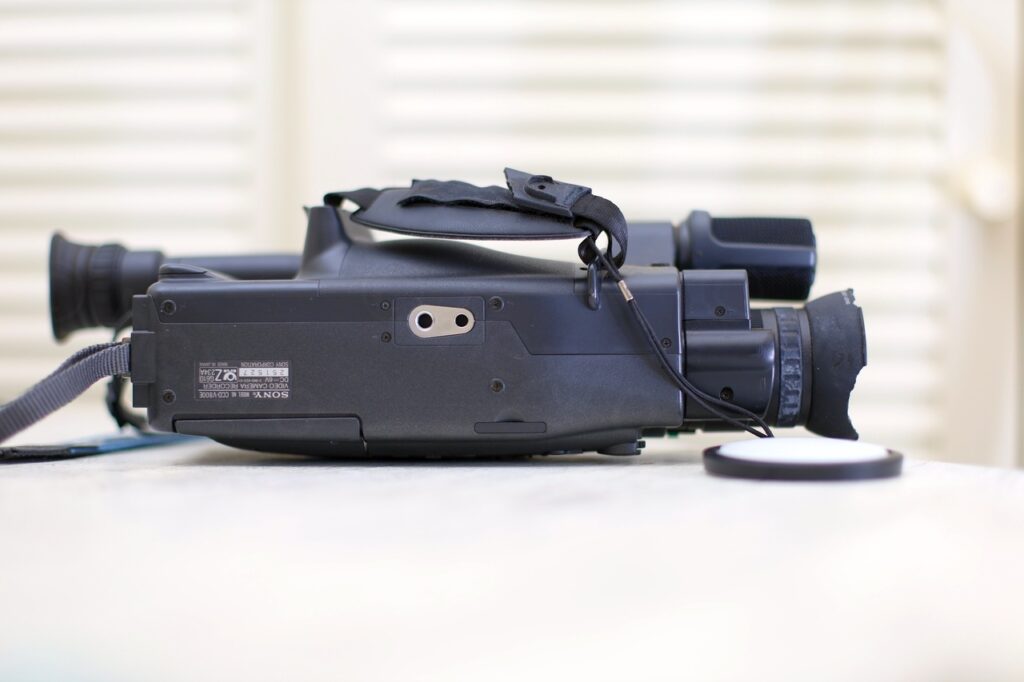
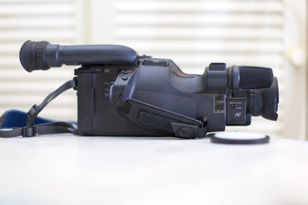
Except a problem with the lens hood which was cracked, camera did look well maintained.
Opening up
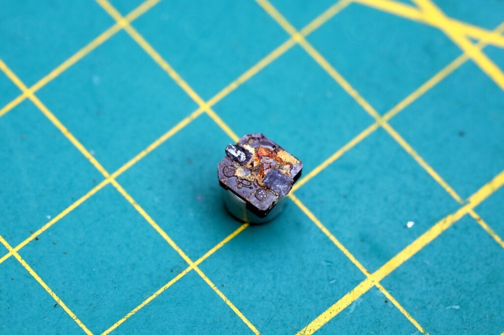
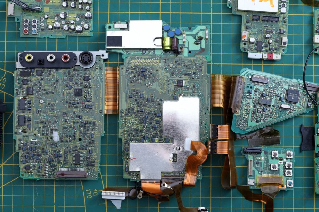
I proceeded with dismantling it (which was rather easy, many screws but no hidden catches). Very quickly I got the first sign of troubles ahead – an SMD capacitor so corroded that it just fell from the circuit board. Ooops.
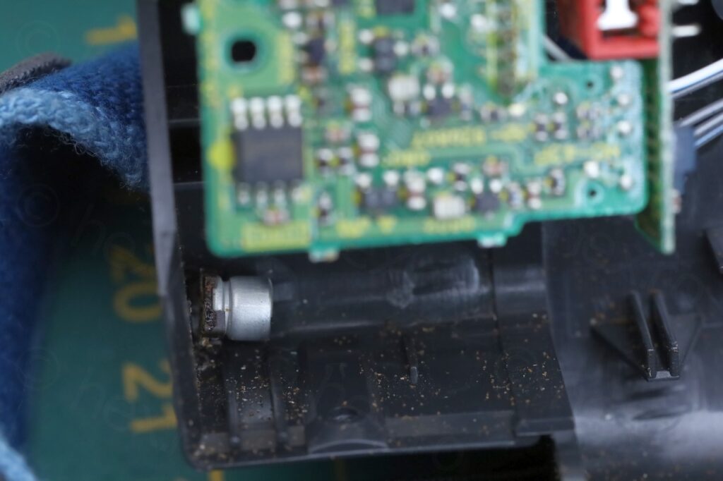
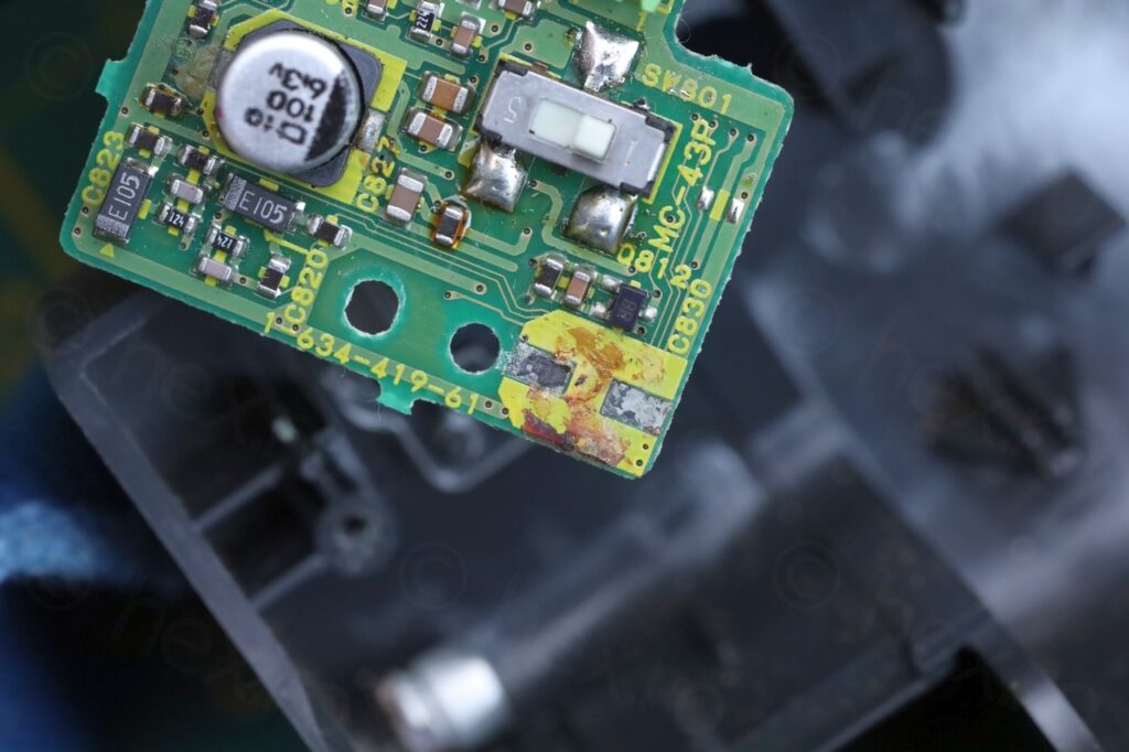
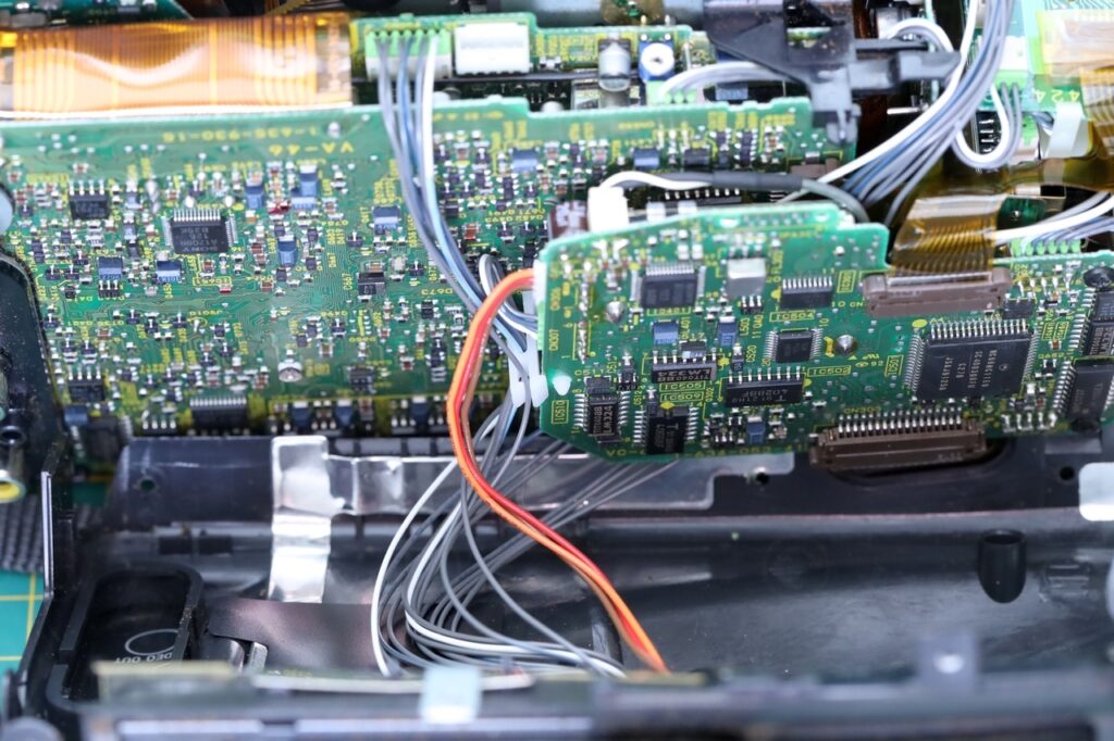
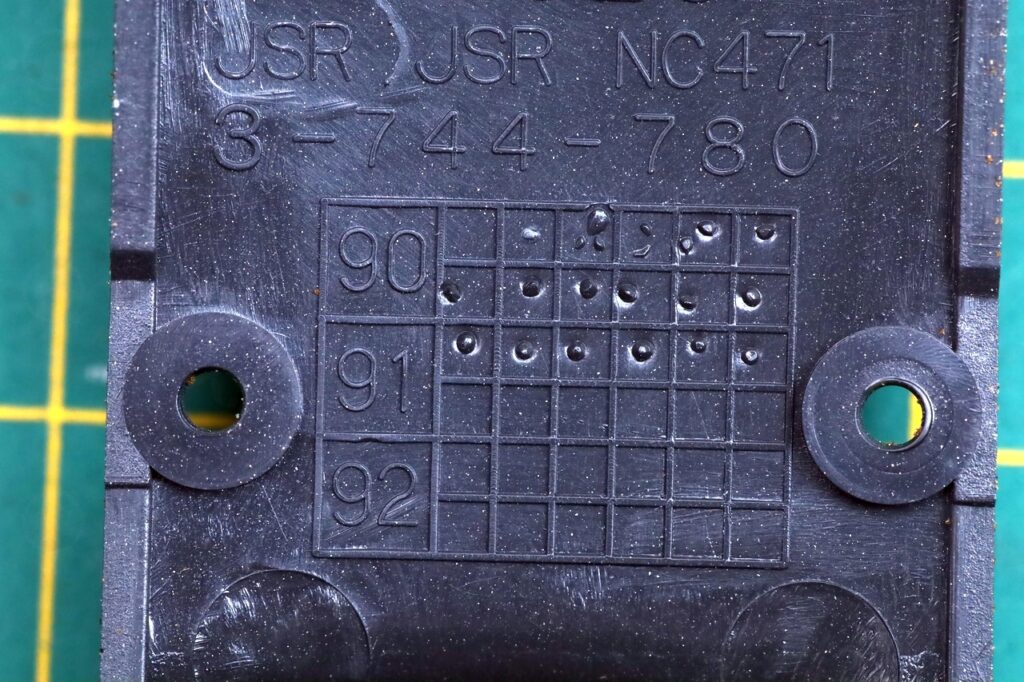
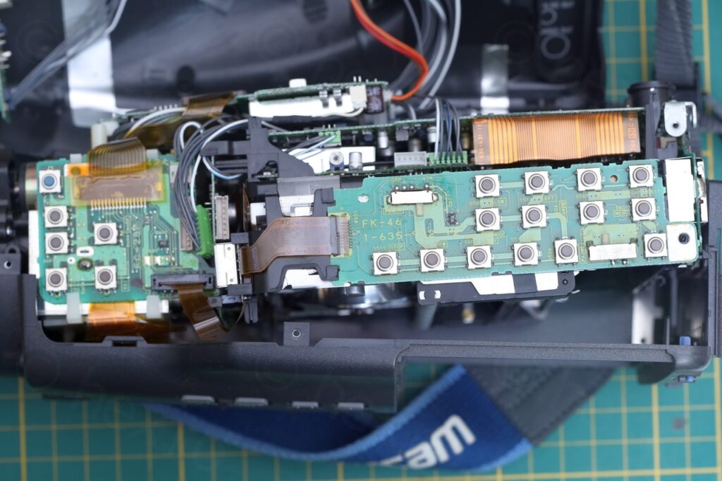
Few more photos from inside, at least there was a good sign, wires connecting the Electronic View Finder unit – instead of flat cables that are a little harder to work with. One of the plastics had manufacturing date stamped to June 1991.
It was time to start investigating the EVF unit.
EVF Unit (VF-27)
According to the service manual, this camera could have contained one of the two VF-26 or VF-27 boards. It turns out that mine had the VF-27 board. Having the service manual is extremely useful in case something goes bad, so I proceeded with some confidence that I may be able to salvage it.
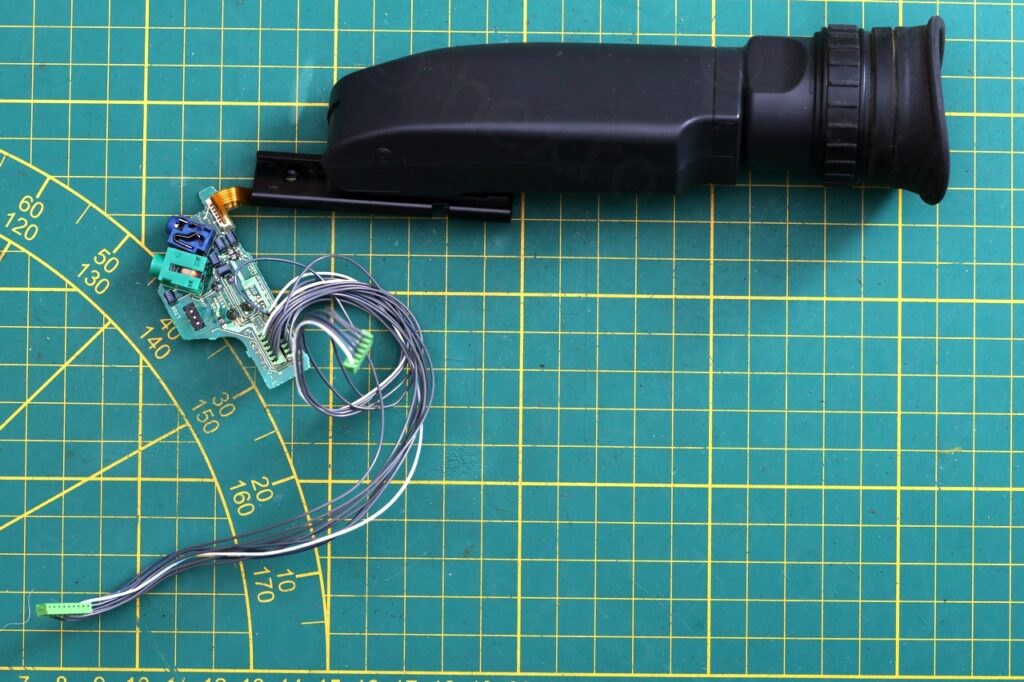
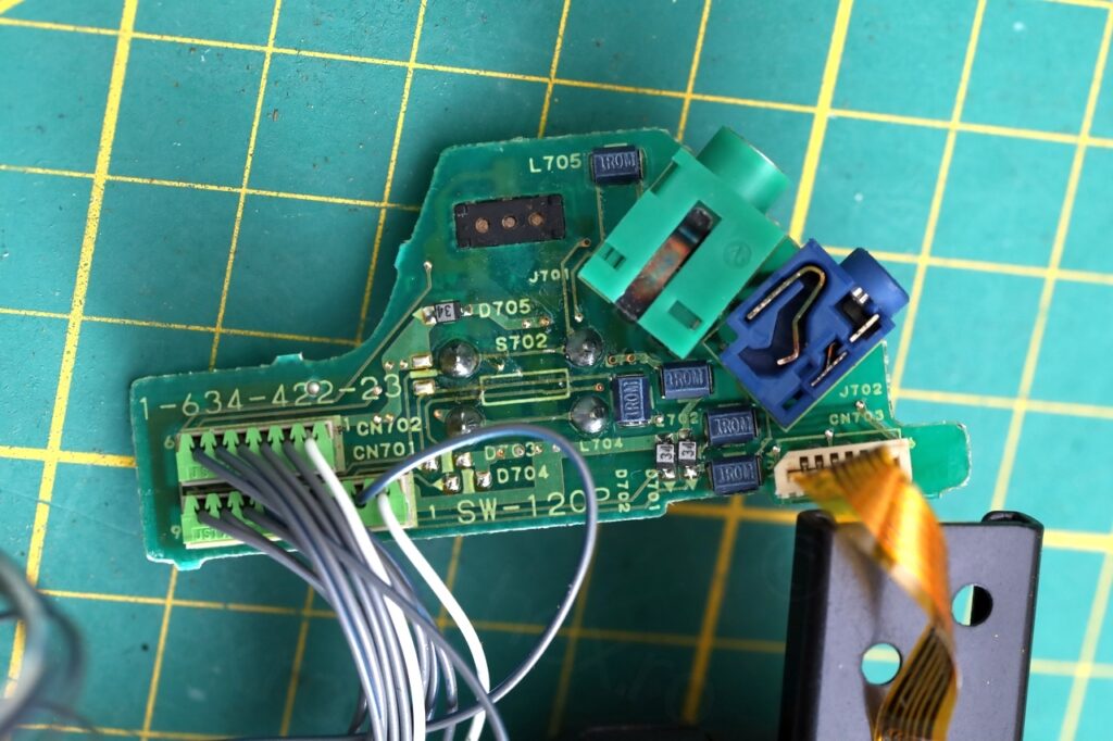
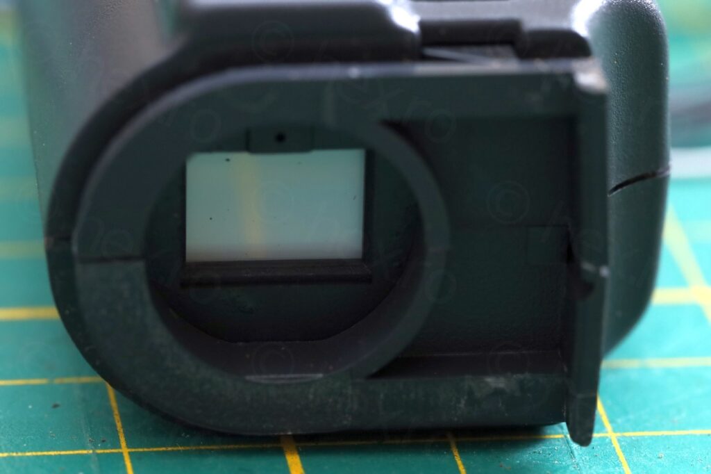
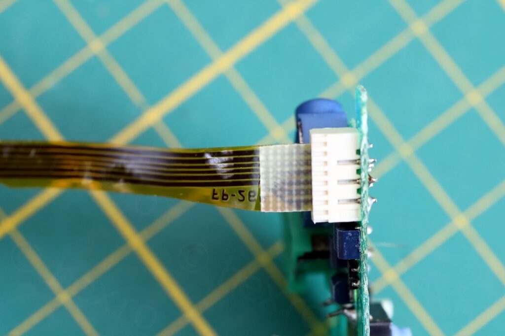
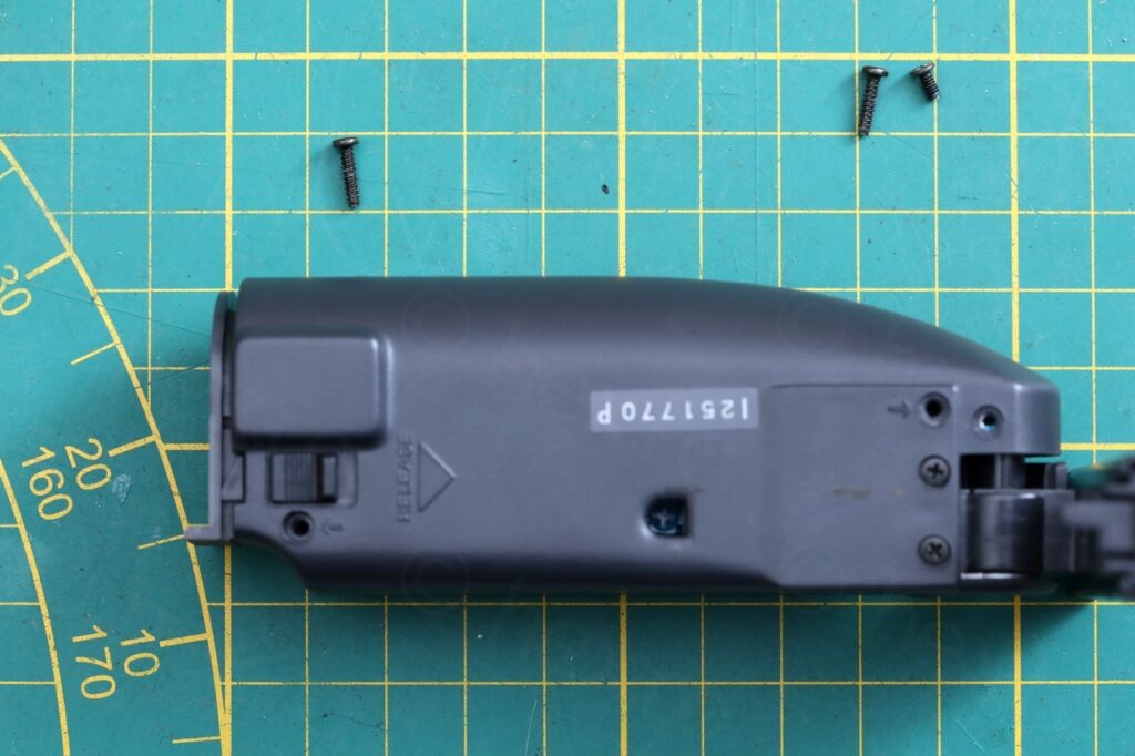
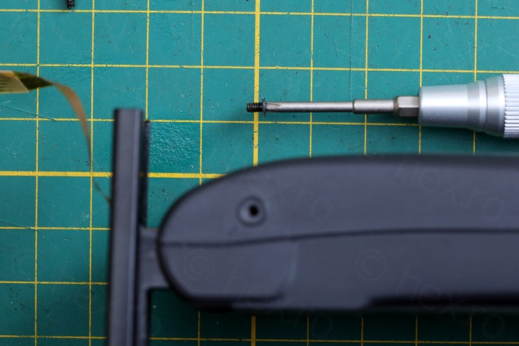
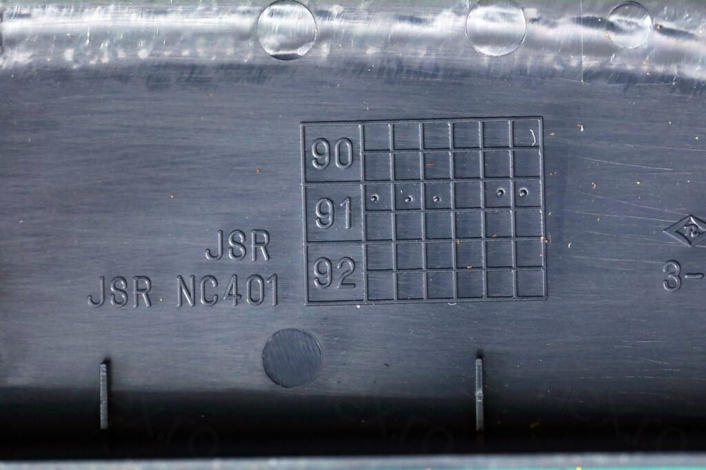
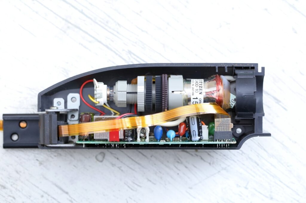
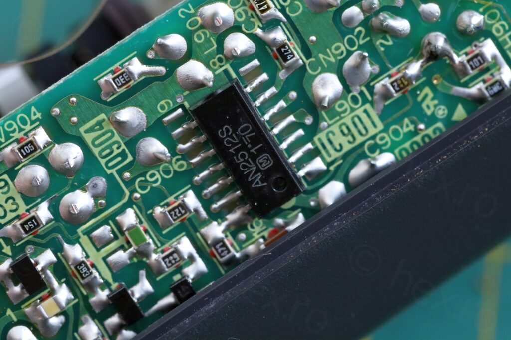
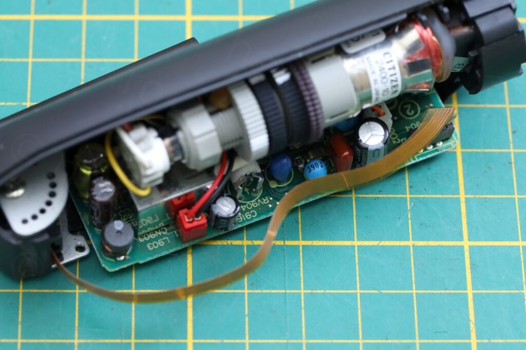

The CRT used is a Citizen 2400-10 which I found in another Sony camera – and surprisingly , the same VF-27 board! I knew then that I will probably encounter the same issue with leaky capacitors.
Flickering CRT
I identified the signal pins with the same algorithm: the case of the FBT is connected to GND, but there are other non-GND pins having continuity to the connector, those are VCC. Some trial and error to identify the Video IN signal.
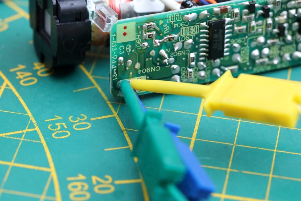
It didn’t work properly. The screen was flickering, was bright and out of focus:
Capacitors swapping
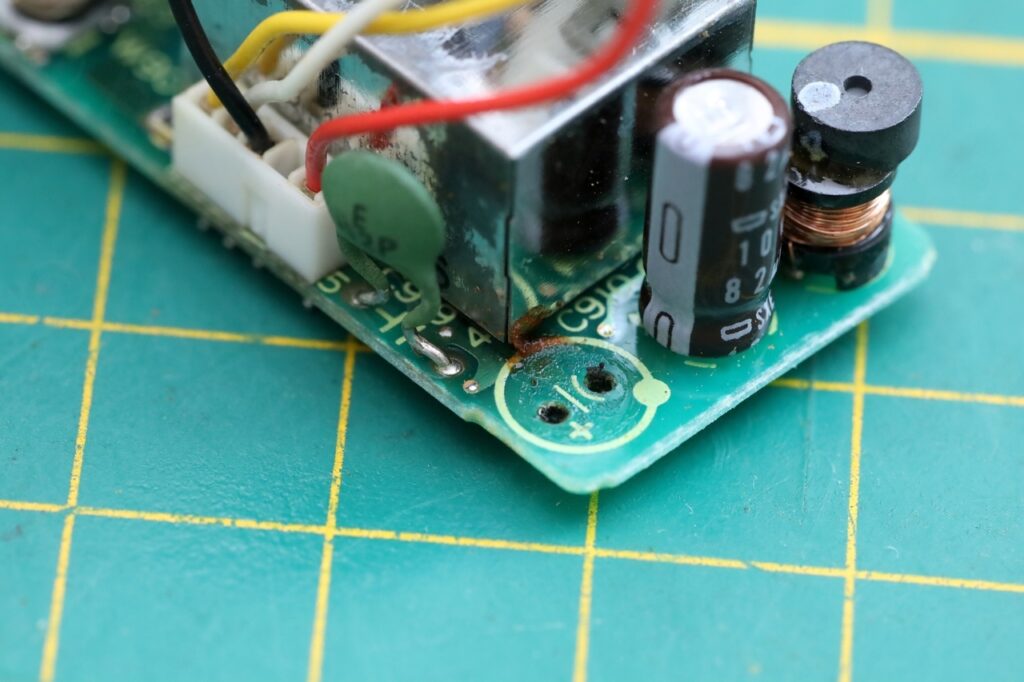
Two of the capacitors were not having a good ESR and on top of it, there was a smell of fish coming from the board – a dead giveaway of leaky capacitors.
I proceeded to swap them one by one to see what impact they have an. Not only that, but I was noting down also the behavior without the capacitor installed.
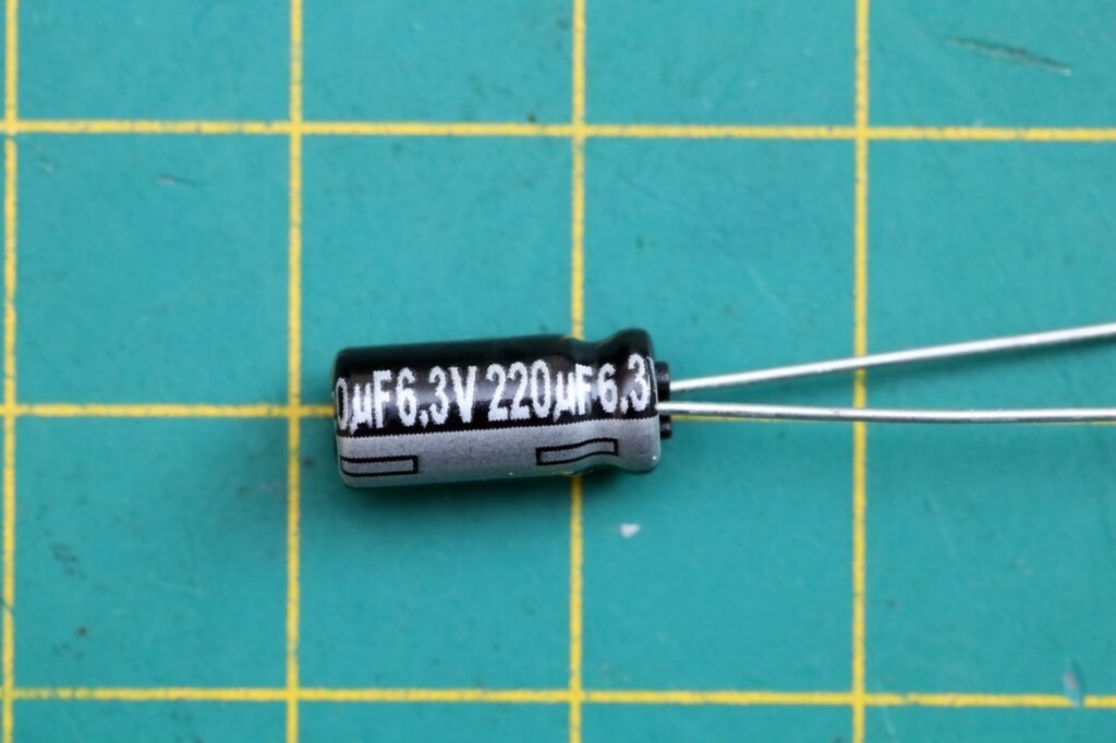
- After replacing the leaked (C910) Elna 220uF 6.3v -> no change, still flicker-y and bright, and stabilizes after a bit. I did not test what happens without it in circuit.
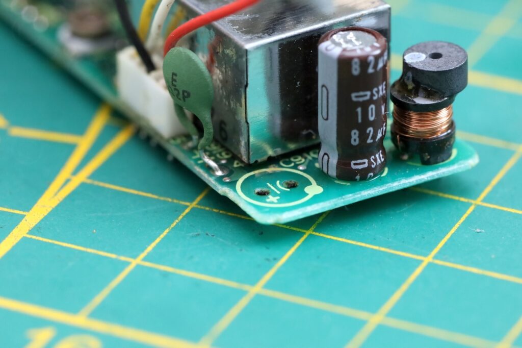
- Without C915 (82uf, 10V) -> bright vertical line in the middle of the CRT (horizontal deflection); After replacing C915 -> no more flicker, but image still very bright.
- C901 (330uF@6.3v) -> no change, and it seems to work fine without it in circuit too.
- R904 (big blue potentiometer) does reduce brightness, but the thing is way too bright anyway, to make a difference.
- C916 was measuring ESR > 40ohm. Without it in the circuit, there is a weird ringing and image looks with many vertical bars. Replaced it, but now it started flickering again, although with moments where the brightness was right.
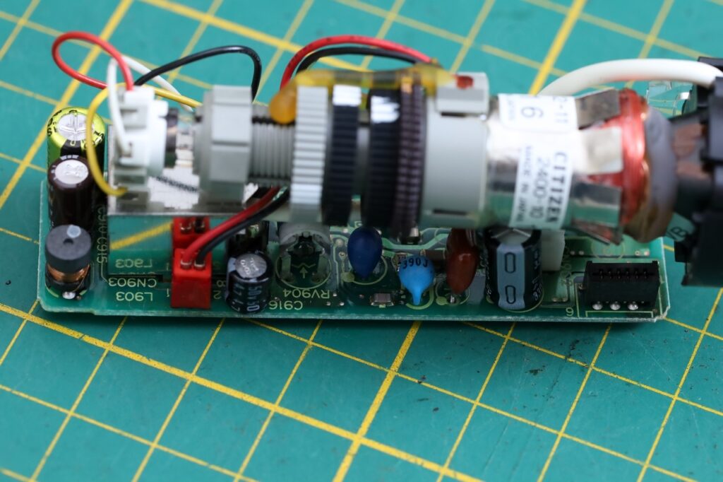
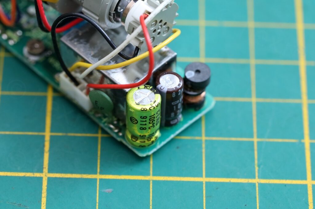
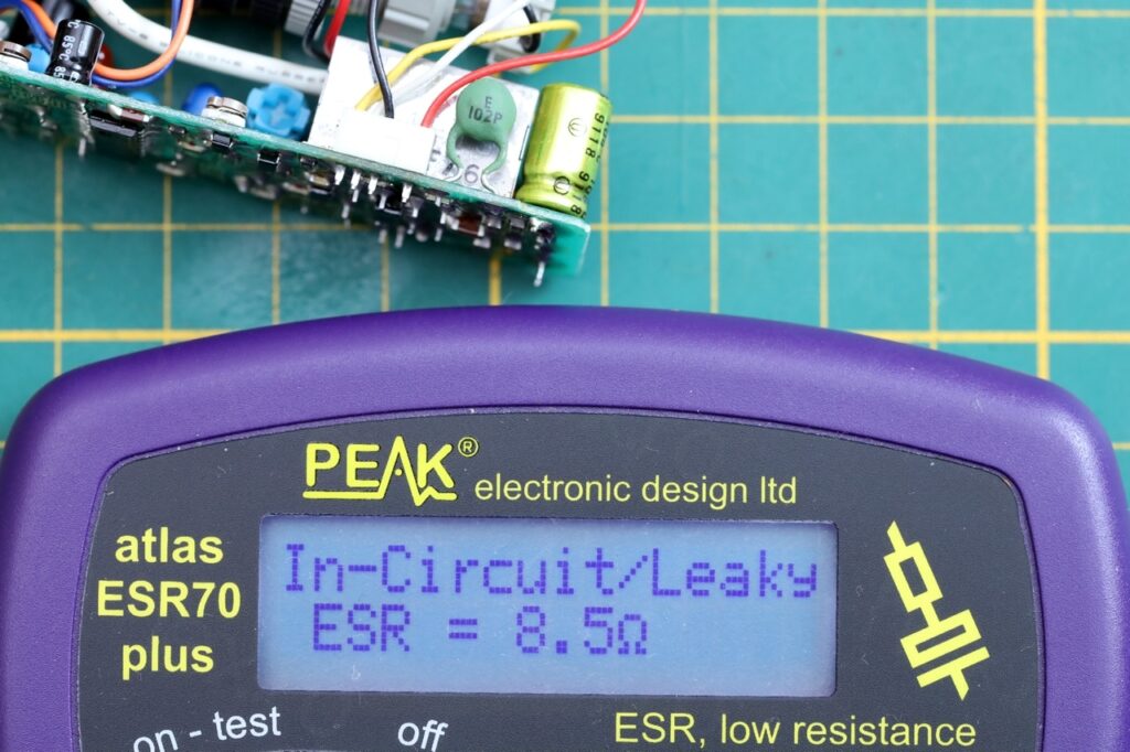
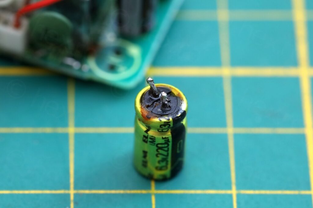
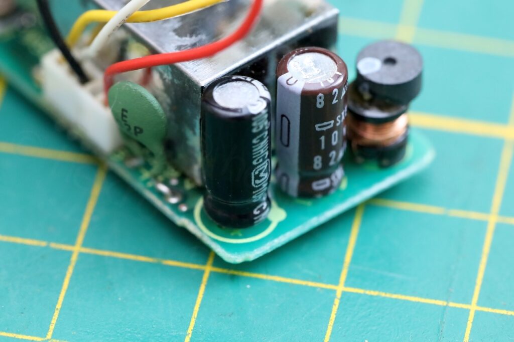
Started to worry about a tantalum capacitor that is there, but hard to read the value.
The other capacitors seem to have a low ERS, not changing them.
W901 connector “shorted” by conductive electrolyte
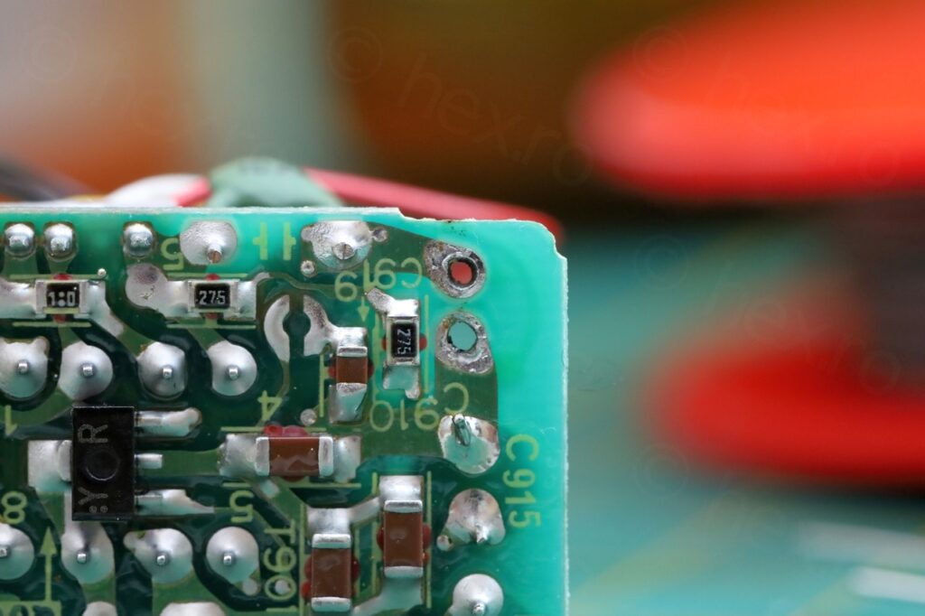
The breakthrough came while pushing the connector W901 towards the FBT, where the brightness seems to recover properly. What if leaked electrolyte got inside the FBT ? There seems that FBT the corner that was dirty hides C911 ..
When re-flowing the 4 pins of the connector, I sensed a strong smell of capacitor leakage. So there was capacitor puss under the connector and the motherboard. Decided to de solder and clean underneath with IPA.
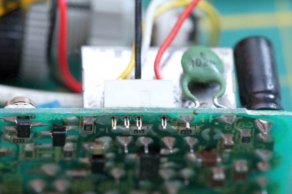
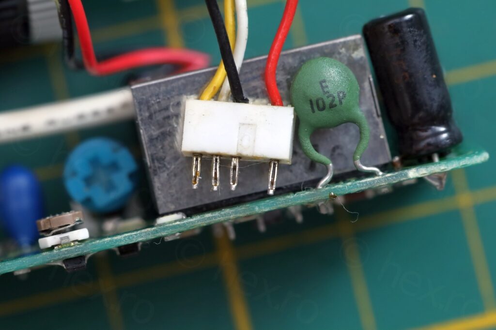
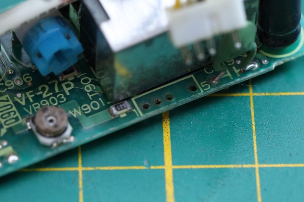
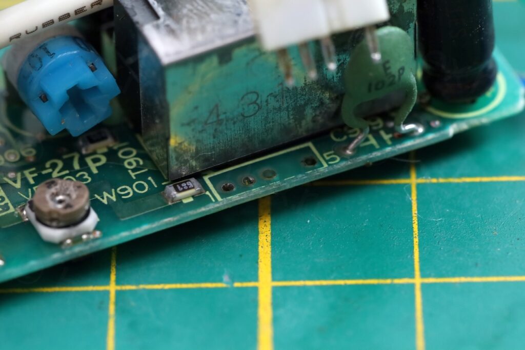
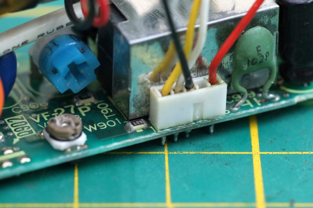
After cleanup under the connector and then re-soldering, everything works now 🙂 this was the final problem.
Not only the image was either overly white (or dark) but it was also totally out of focus (blurry).
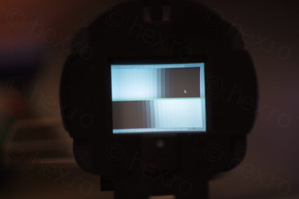
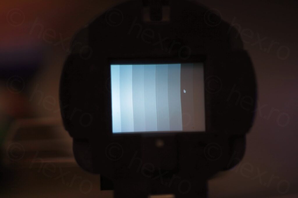
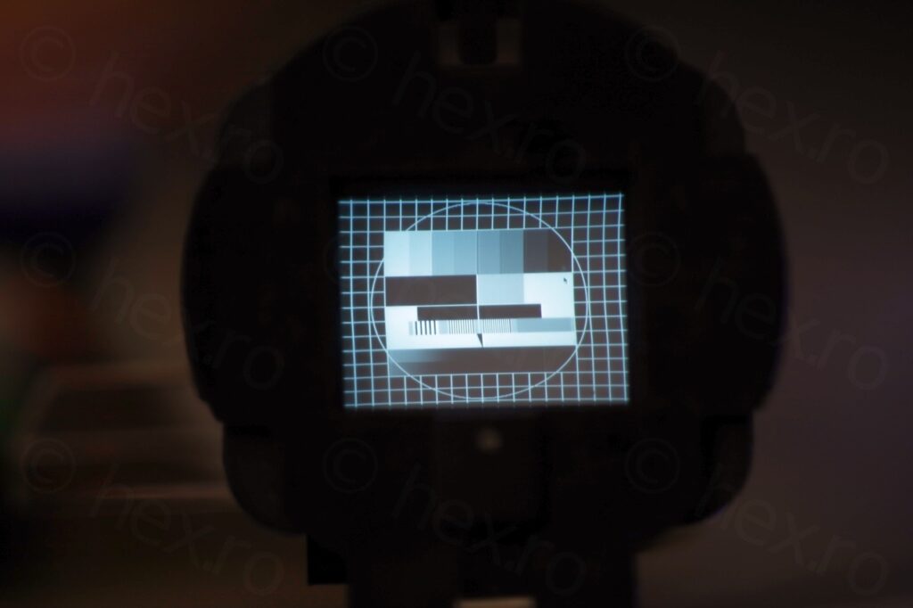
Another challenging board, with electrolyte reaching places I didn’t consider. But it works.
More photos
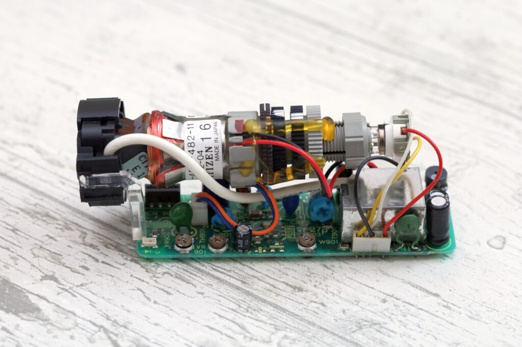
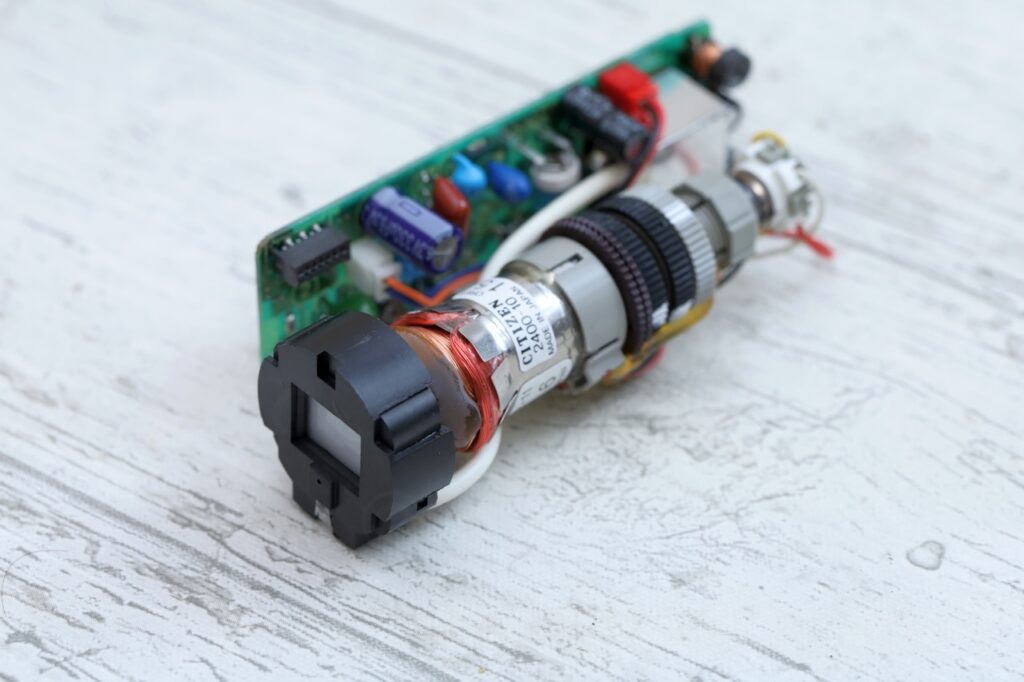
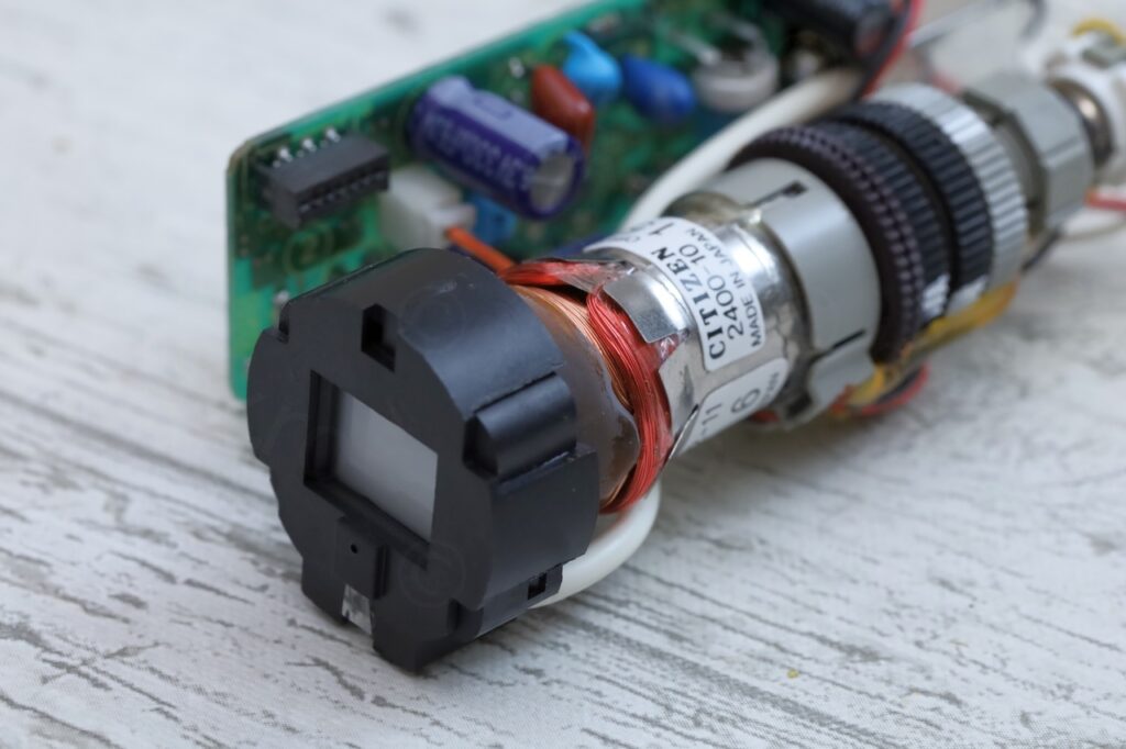

SA4HMR
Hej,
how do you connect something on this pcb?
You have a tv-signal, where do you found this signal?
I am interested in a CRT-Clock (as osci-clock), how can I put the X and Y signals there?
Thank you very much.
Sincerly
Harry.
qf
@SA4HMR
Harry – the driver is intended draw a raster to take a video signal.
Providing XY deflection can be done, but it’s a bit tricky for a few reasons…
XY is usually done with electrostatic deflection – it’s very linear, able to work with high frequencies and is low current, low reactance (tiny capacitance and inductance) so easy to drive – however, this CRT has no electrostatic deflection plates and uses an electromagnetic yoke. Dismantling that would probably affect the HT as the 15kHz scanning ramp is often used to drive the HT transformer – so there’s work to do to separate those deflection coils from the board to drive them yourself… the inductance of the coils might be required to keep the oscillator running to get the HT
🙂
Good luck!