
I discovered that one of my Dell Optiplex 7040 Micro PCs was stuck at 800 MHz.
Table of Contents
Discovery
The source of these computers was various local secondhand shops. I figured that a company had refreshed their IT stock as these PCs popped up almost at the same time in the shops. Initially I got one on account of running a small dedicated server. They didn’t seem to sell though – the shops started to drop the price which encouraged me to get few more. Now the goal was to work up towards a small stash of them, a tiny “datacenter” running Proxmox!
Got them stashed, hooked them up, and, time permitting, setting each one up with Proxmox, and finally configuring the cluster. They didn’t get much use after this .. except setting up the network isolation, the metrics, trying to move a small VM, etc. At one point, I decided to migrate Proxmox to a newer version, an operation I started in parallel on all nodes.
That’s when I noticed that one of the PCs was running much slower than others. And long story short, this article. Now the PC is fixed and stash is running again normally.
Attempts at Diagnosis
BD PROCHOT signal was present but Dell’s RTC reset procedure did not fix the problem. I tried using a different Dell 65 W charger, but CPU was still stuck at 800 MHz:
root@pve3:~# /usr/sbin/rdmsr -a -d 0x1FC
2359389
2359389
2359389
2359389
Trying the suggested online fix …
wrmsr -a 0x1FC 2359388… works fine, and I have even added this to GRUB.
With the software fix, the machine was running perfectly, no thermal spots – nothing getting hot. But I started having a nagging sensation that I must find the fault, otherwise I wouldn’t feel safe leaving the computer unattended.
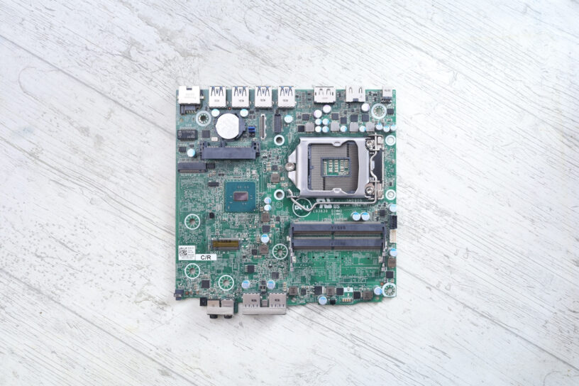
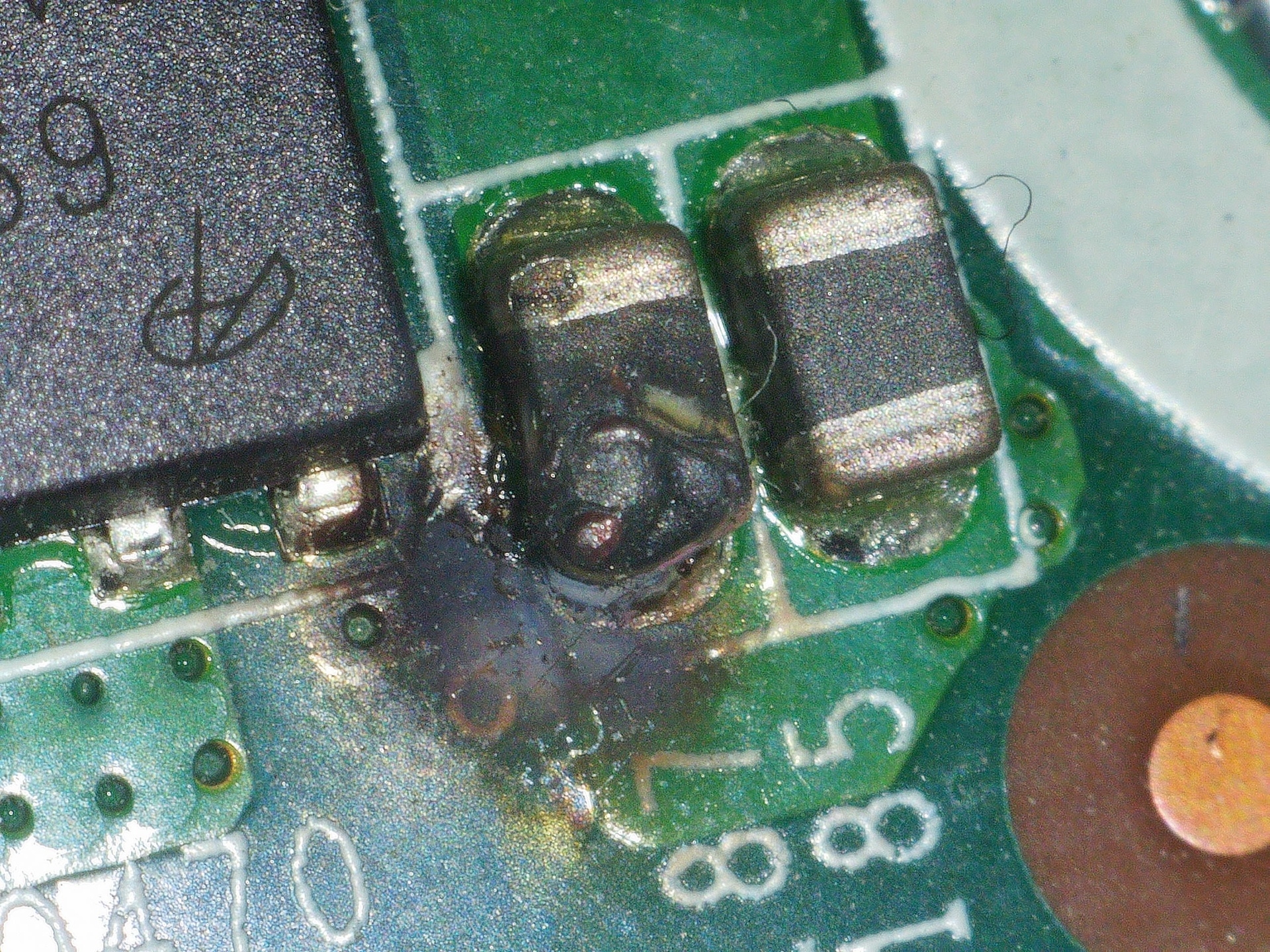
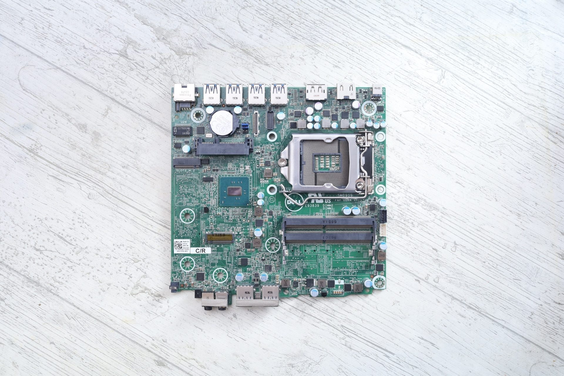
I took the computer out of the stash and tried to look at the motherboard (which, I should have done when I installed them, but I didn’t …), and lo and behold:
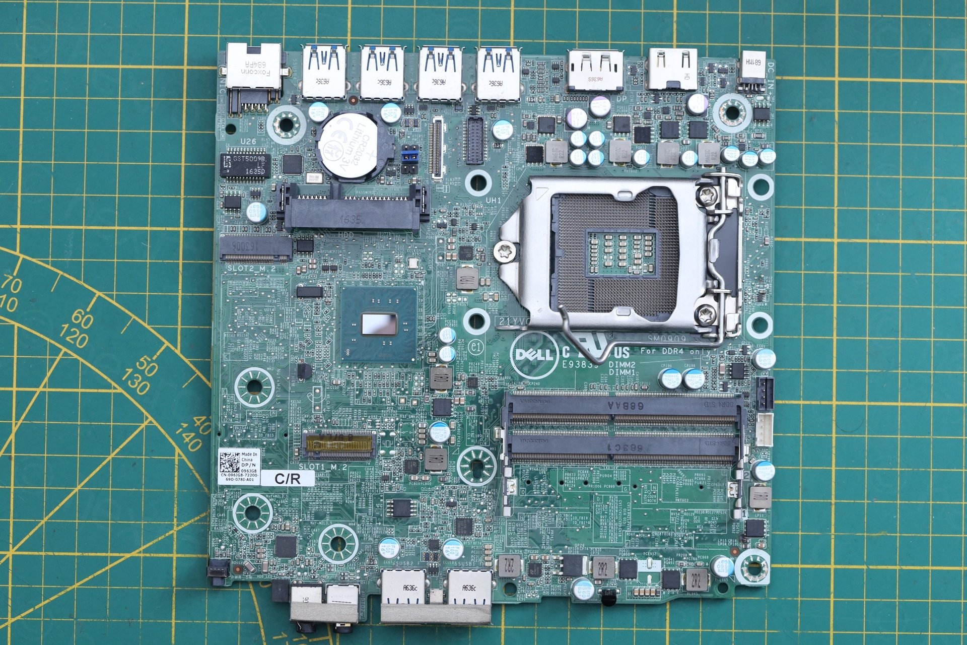
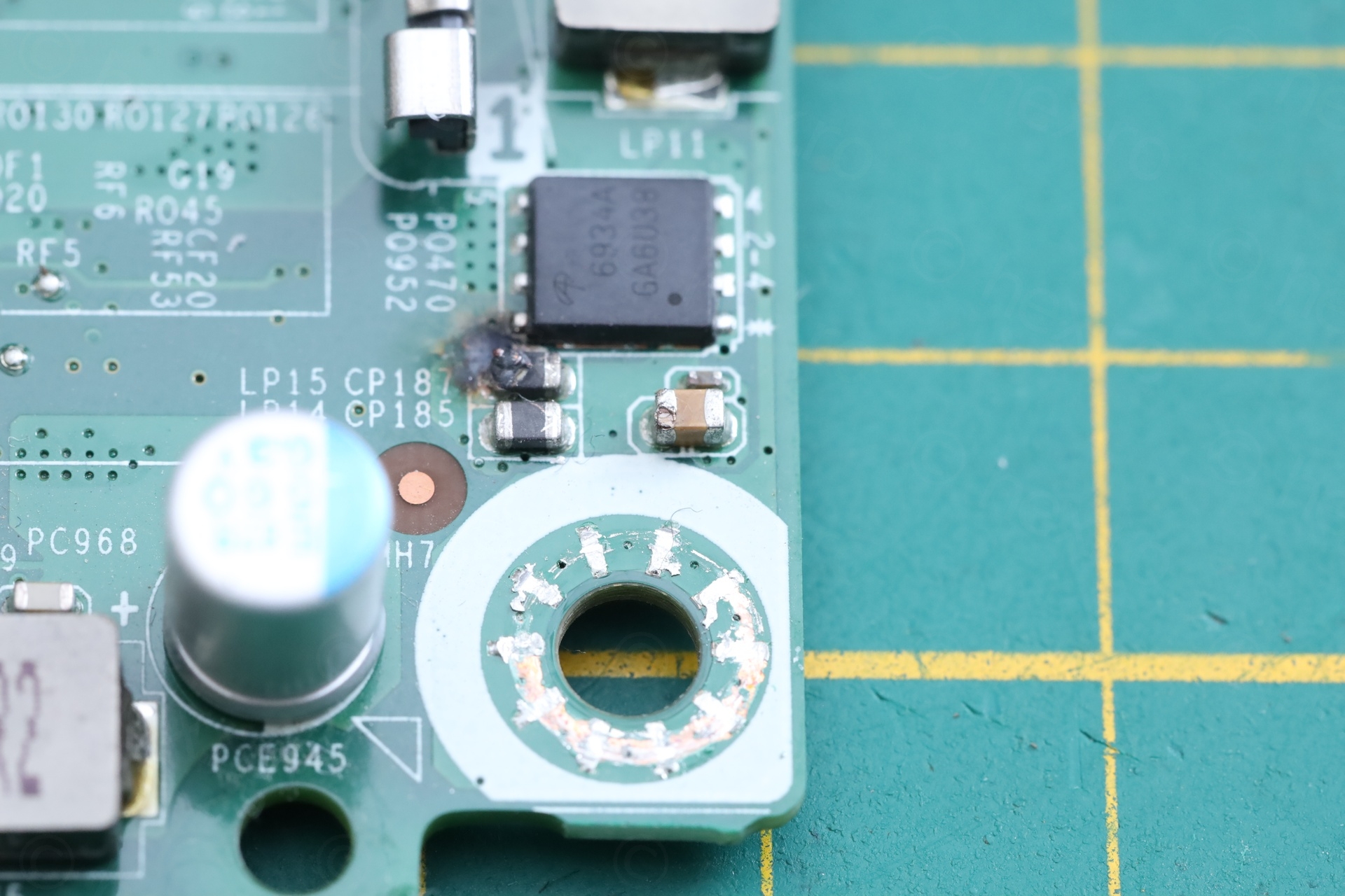
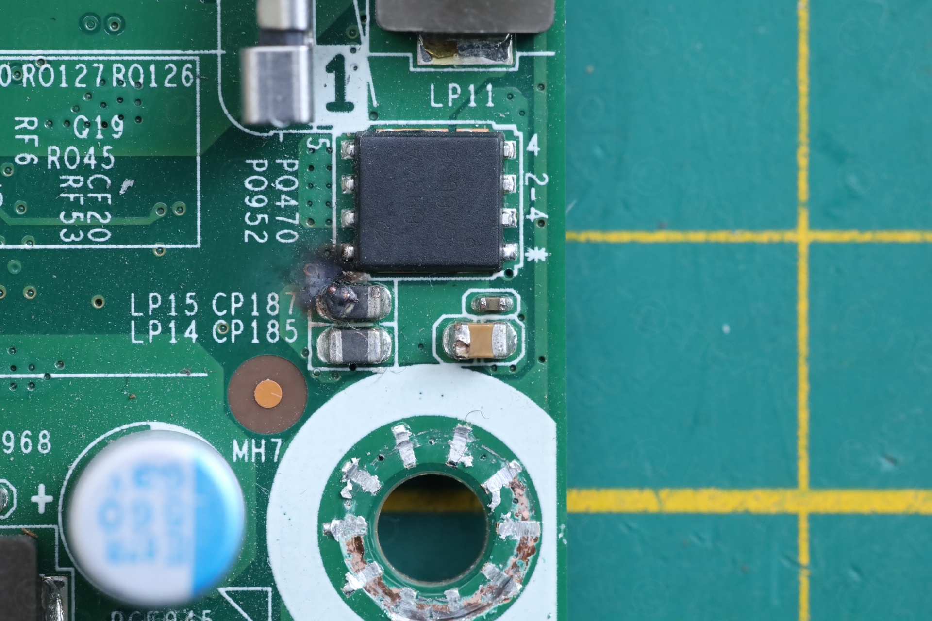
One ferrite bead was burned.
Fixing this board took me a lot of time due to various constraints:
- Was not able to find the schematics / board view for Dell 7040 Micro even if, according to Dell, the warranty expired 7 years ago. I did find the schematics of Dell 3070 MFF and Dell 5050 MFF which, luckily, were very helpful.
- Since this fix required low level board repair, I was afraid of using one of the working ones to compare. What if I slip with the probe and I end up destroy a working one ?
- I went onto few wrong directions before I identified the culprit.
- Waiting for parts and exploring few possible diagnosis paths took time. Meanwhile, I ended up with even more Dell micro computers (found a different shop that had a two broken ones and found few very very cheap – without memory and hard disk – at the local flea market).
- One of these other Dells came with a 90 W Dell official Charger – surprisingly, the board works fine with more powerful charger! This puzzled me a lot, how come ?
I am now convinced that somebody dropped a small screw on the motherboard while assembling the PC – tried to measure here and there, but gave up ..
Is it the ferrite bead ?
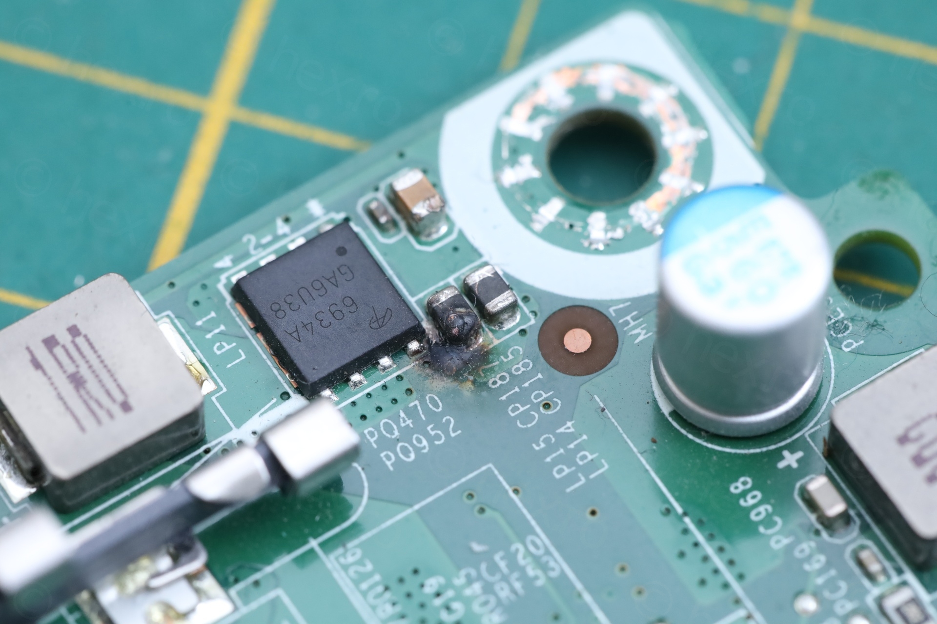
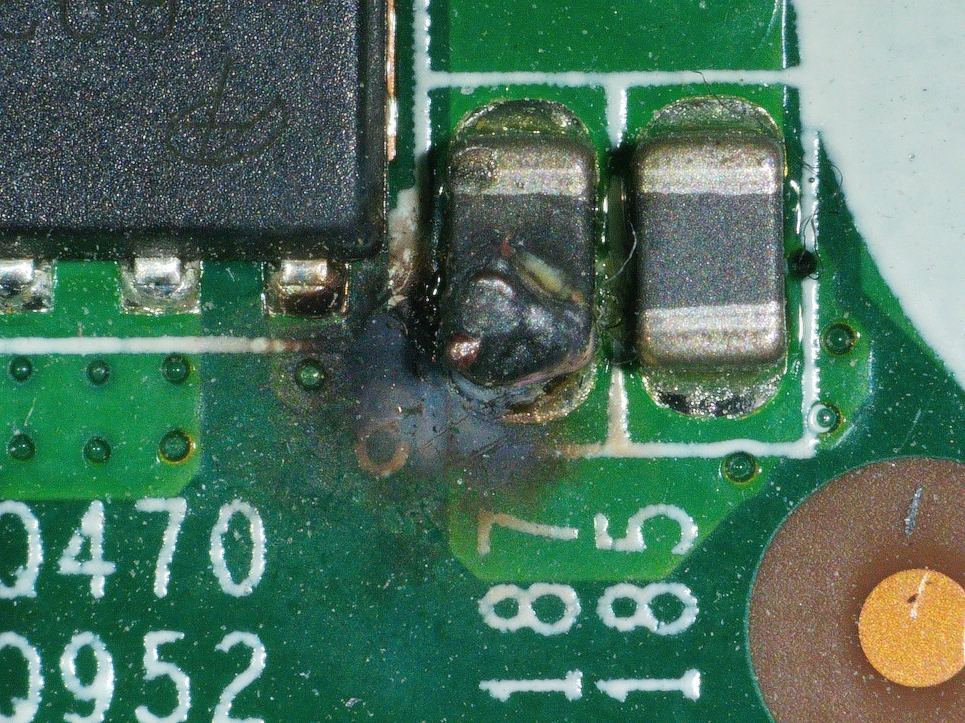
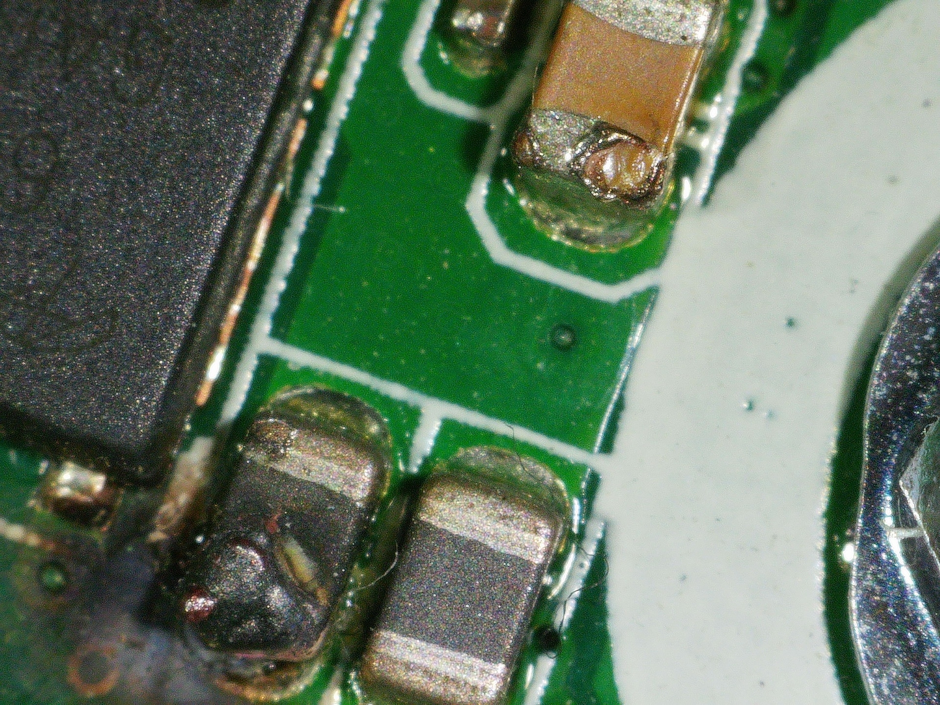
First wrong direction was to believe the ferrite bead is causing problems. It wasn’t. After cleaning the area, measuring continuity of the tracks and comparing to one of the working boards, the area is OK and MOSFETs do output the right voltage. Both of the nearby capacitors seem to have been poked with a multi-meter probe:
CPU pin C39 / PROCHOT#
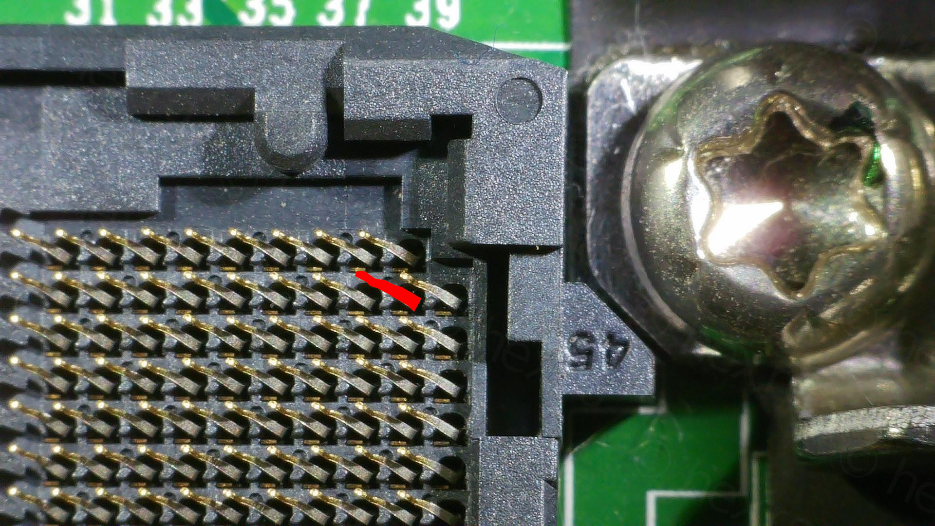
Without schematics / board view, another failed path was thinking I could identify where pin C39 of the CPU (the PROCHOT#) is hooked on the motherboard. This proved to be a waste of time …
Reasons are that it is very difficult to try to find continuity while keeping one of the probes on the C39 pin. Pins are very fragile, so I never knew if my probe was actually touching the pin, or, if the probe slipped and was touching also a nearby pin which happened to be GND. Forgot to mention, the other probe had some solder braid attached to it, so I could just press it down onto the circuit board, touching many pads at the same time and cover a lot of the surface faster.
So I either got no continuity, or constant beeps when I slipped…
This step got me a little closer to the problem, but I didn’t know yet. While looking at the board, I spotted a slightly burned capacitor but it wasn’t shorted.
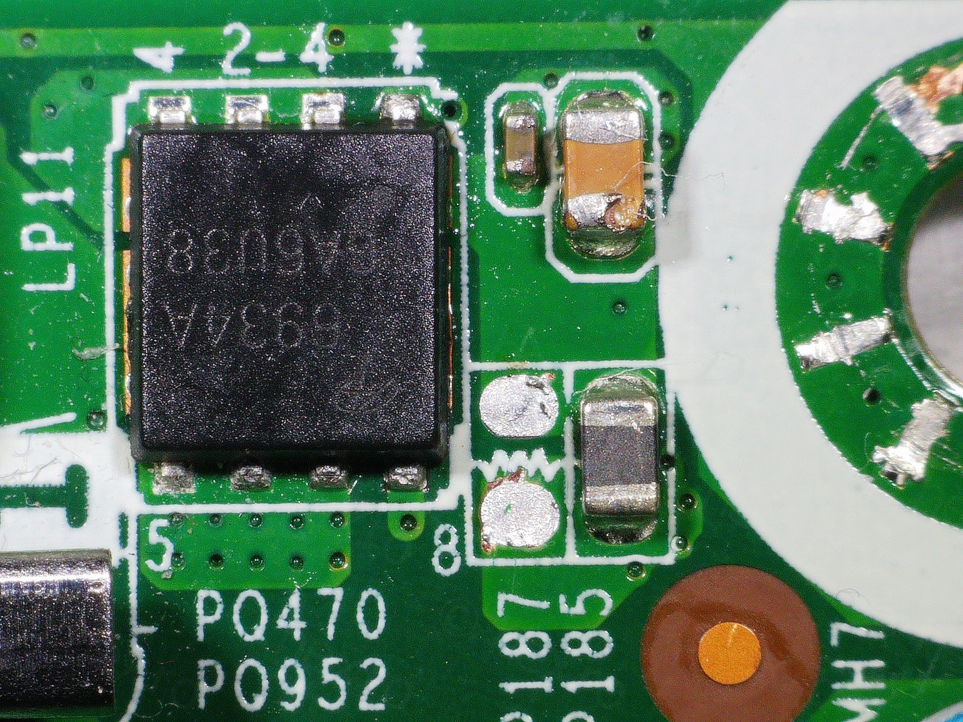
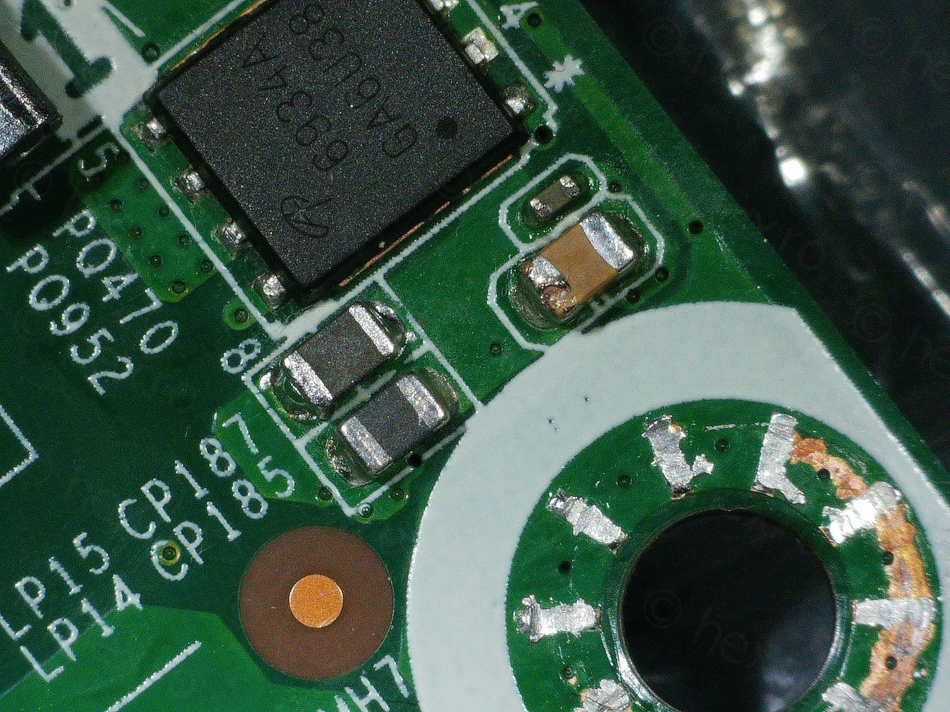
AS393M Dual Voltage Comparator
Since now I spent a lot more time looking at the CPU area, I happened to spot an AS393M nearby, which I recognized as part of the PROCHOT# circuitry from the other two schematics I had (5050 and 3070 MFF).
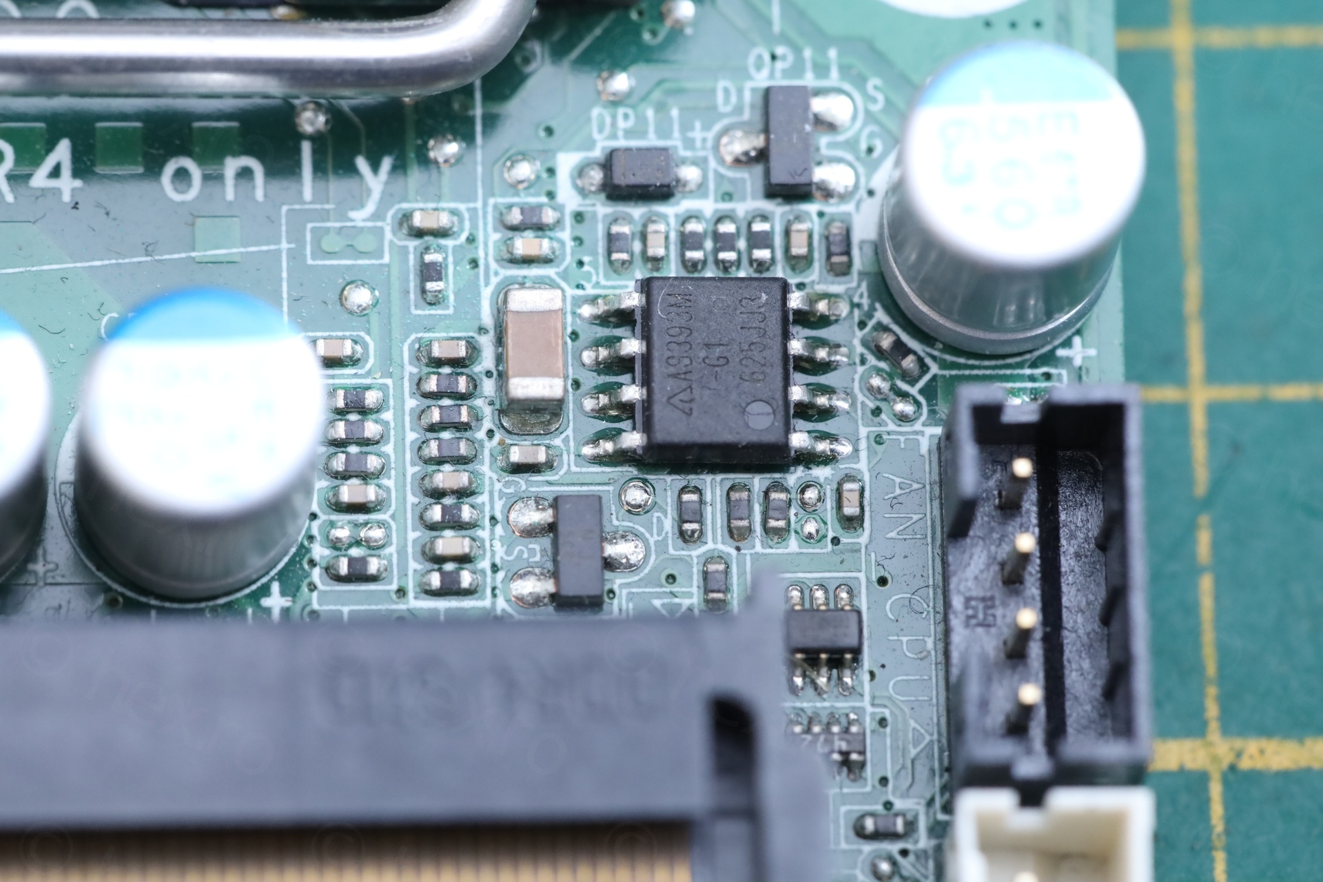
I wrote down all the voltages on its PINs in 3 combinations. A good board with standard 65 W charger, the bad board with same charger and the bad board with the 90 W charger (known to work). In the scan (as in the photo above), PIN1 is in lower right.
PIN1 (OUTPUT 1) participates in the PROCHOT# logic and on the good board sits at 0.034 V. But on the bad board, irrespective of the 65 W or 90 W charger, it sits at 4.33 V .. Similar story with PIN7 (OUTPUT 2), it sits high on the bad board.
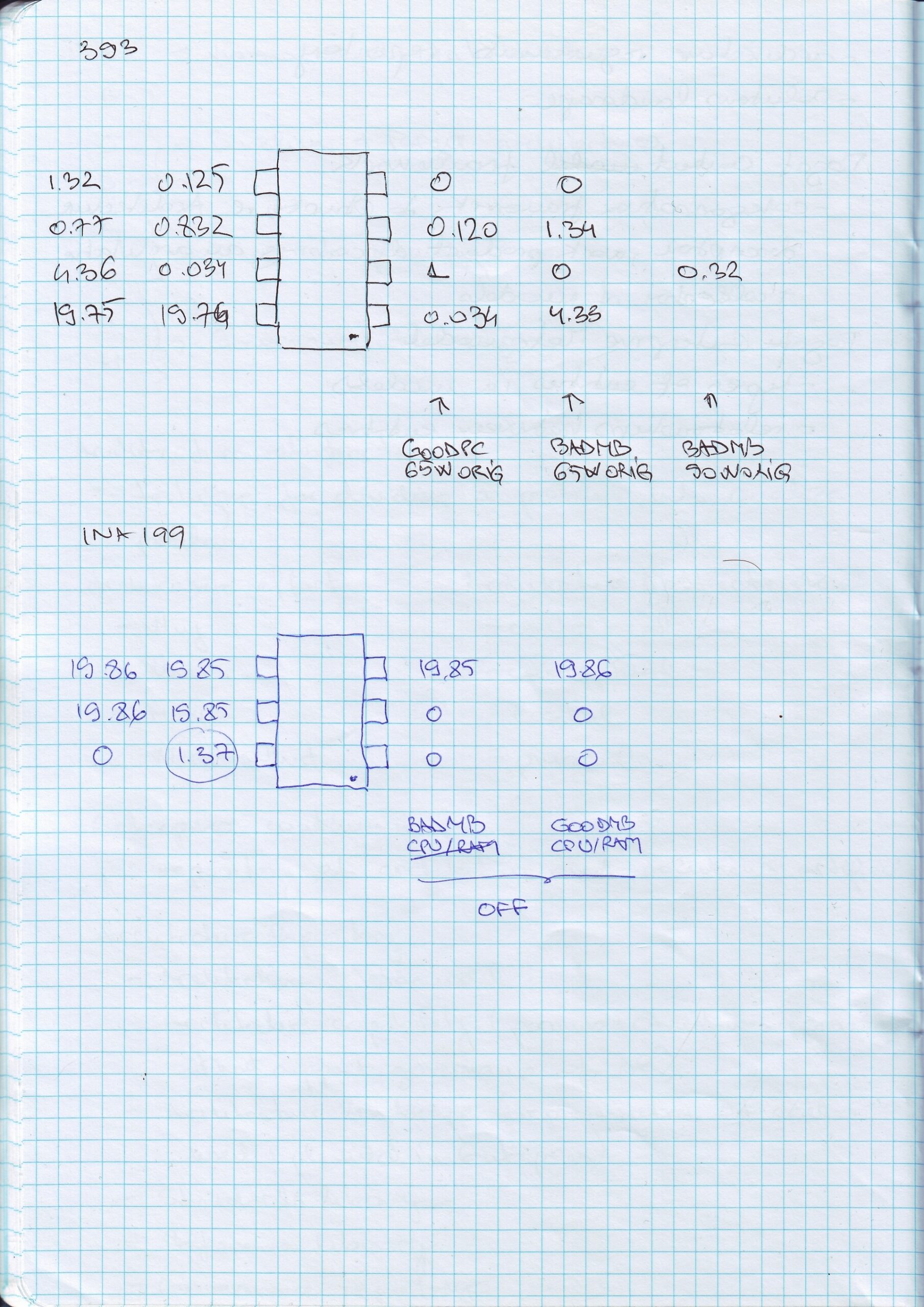
This is what puzzled me a lot. Why, if the outputs are towards 5V, does the bad board still work fine with the 90W charger ?
Upon review of the voltages INPUT voltages, I concluded that AS393M works fine. The outputs are correct, on the good board the INPUT voltages (on PIN3, PIN5) were very close to zero, but on the bad board, these were around 1.34 V.
In the 5050 / 3070 schematics, these voltages are derived from a different IC – an INA199 current shunt monitor. But which one was it ?
INA199 Current Shunt Monitor
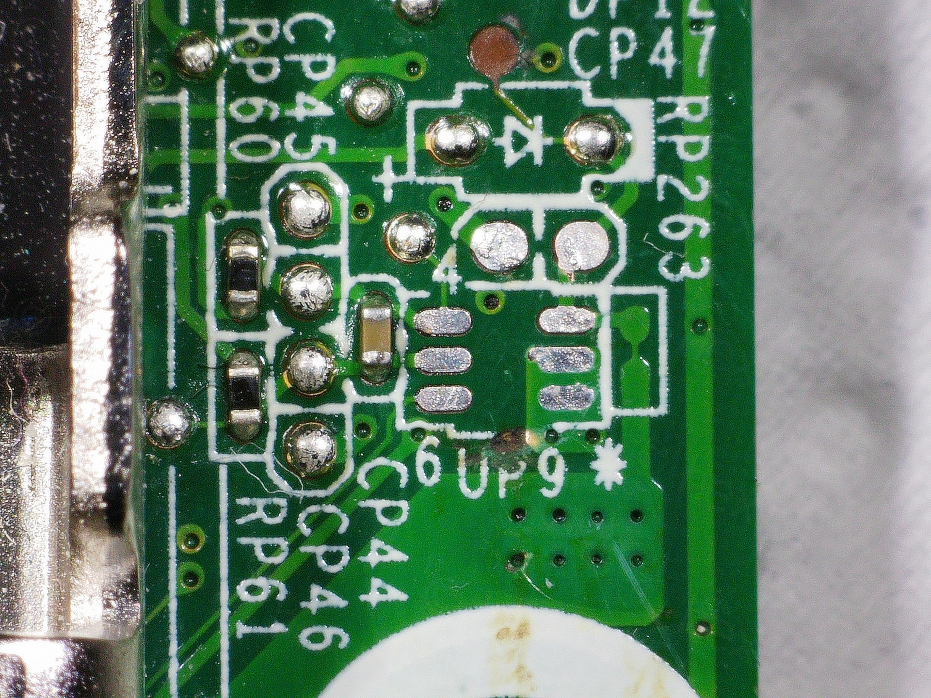
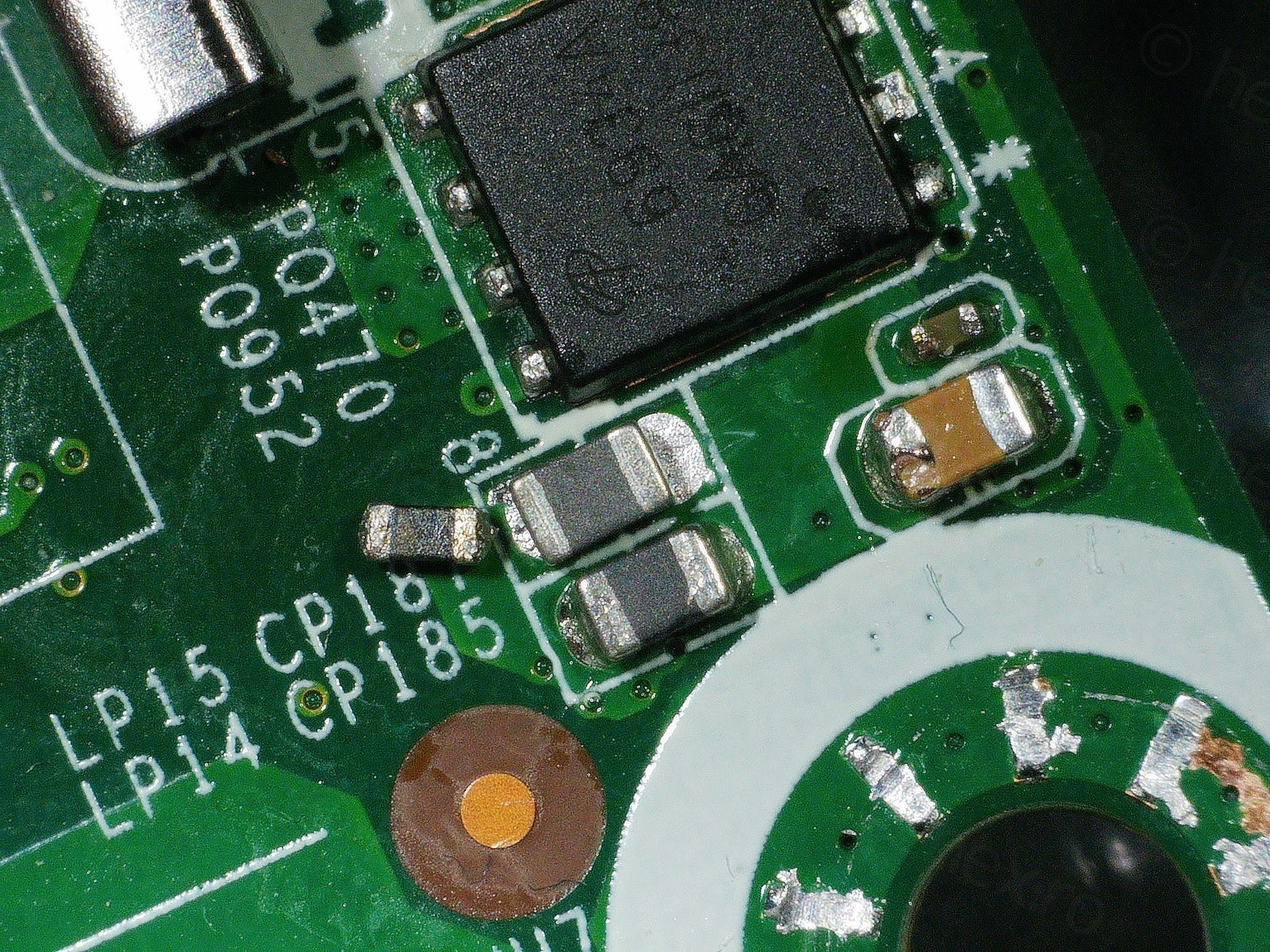
Since I already had the board under the microscope, I remembered seeing the half burned capacitor around the area of AS393M and decided to have a look:
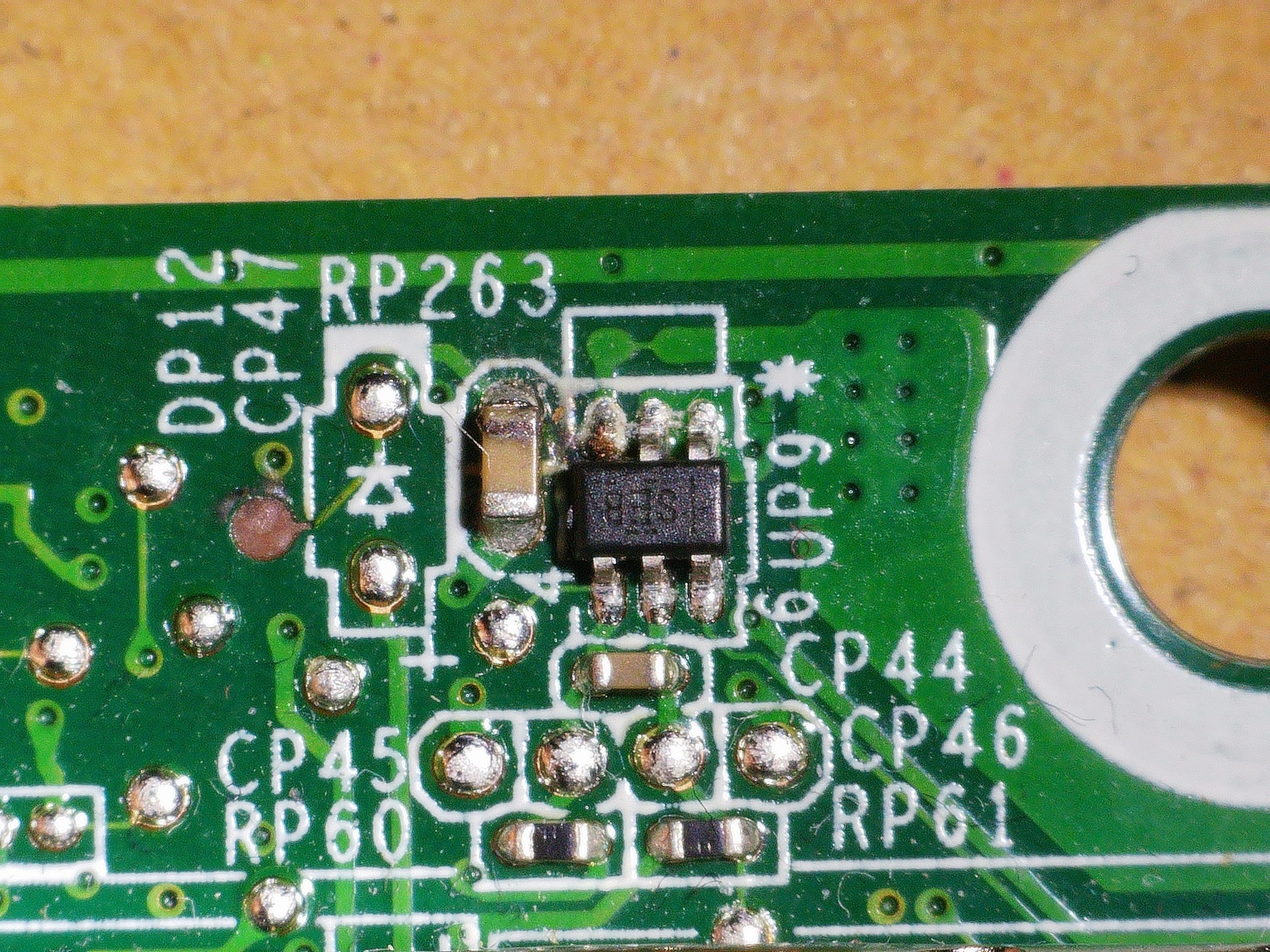
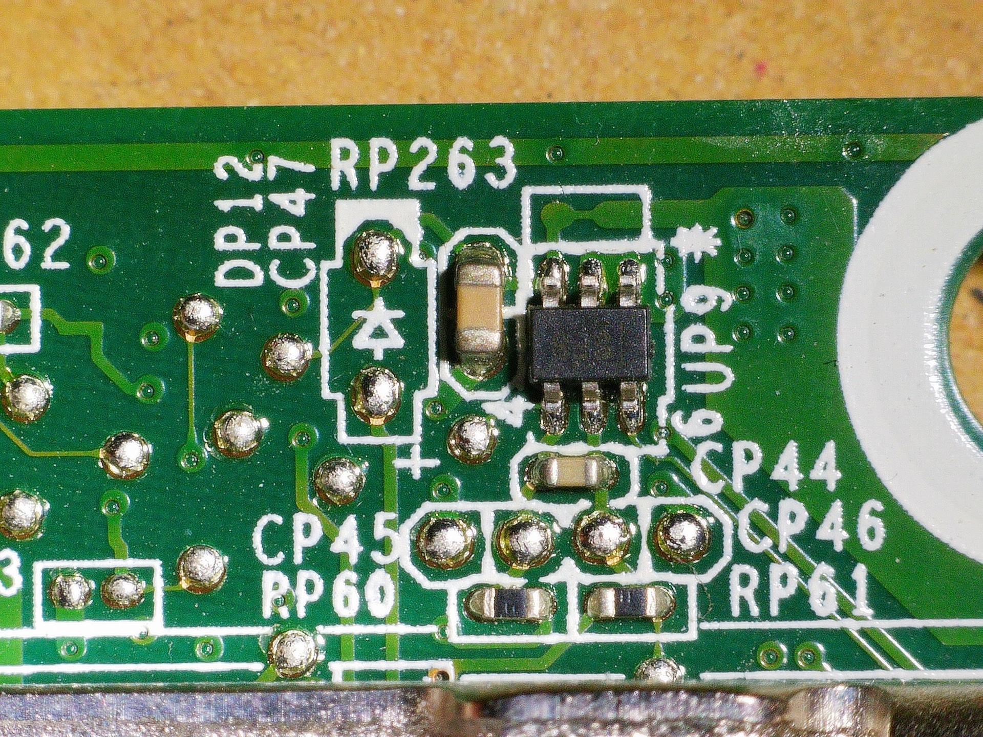
The capacitor was in burned / cracked, but it was not shorted. A pad (next to CP47 marking) was also gone – although it looked like a test point.
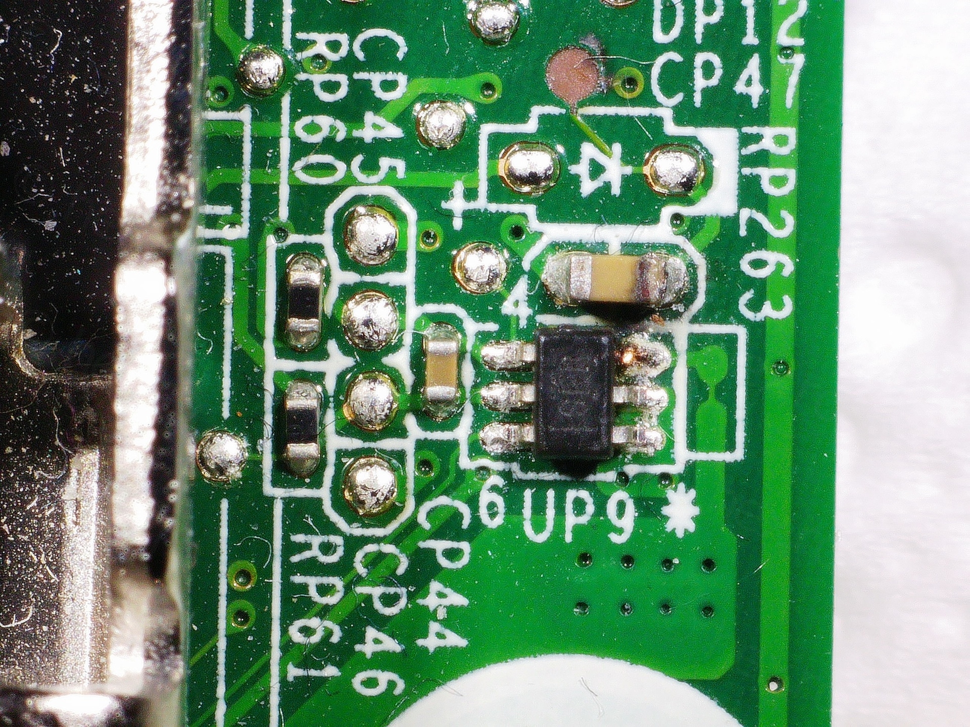
There was a bit of exposed copper on the pin 3 of the IC, the closest to the burnt capacitor as if somebody tried to measure the voltage on that pin.
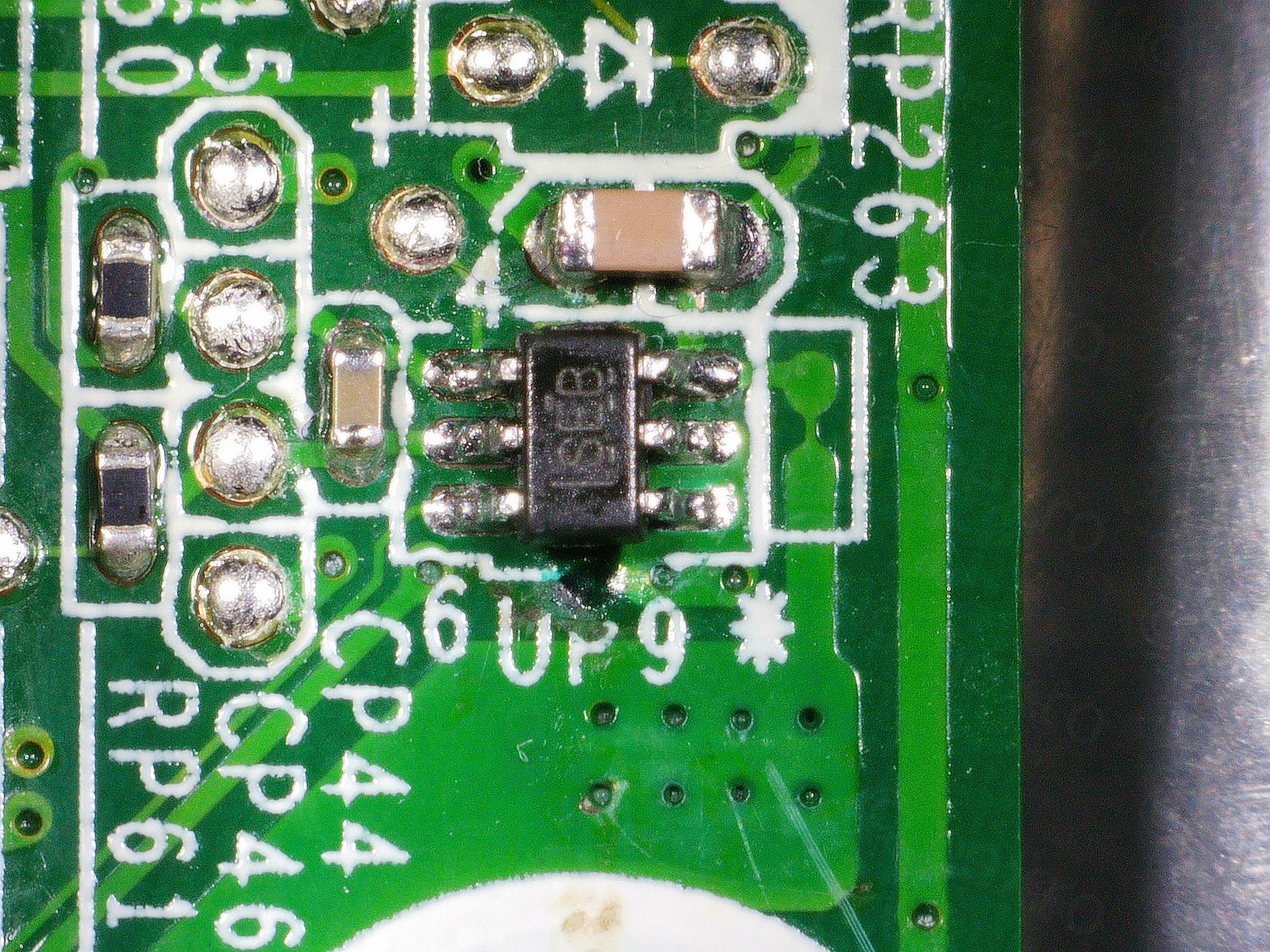
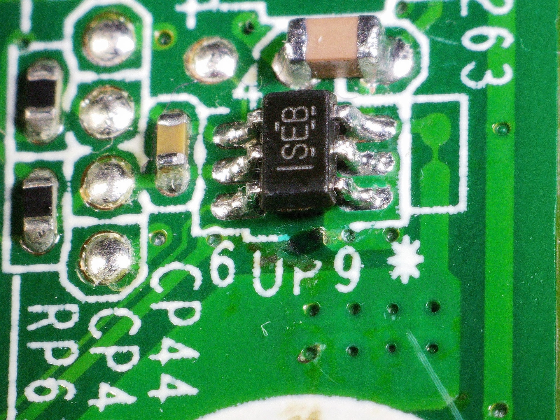
I started searching what the “SEB” and finally found it with Google Image Search – INA199B1DCKR – a Current Shunt monitor. I immediately clicked. INA199 was exactly the IC (from 5050 / 3070 schematics) responsible of creating the two INPUTs for the AS393M comparator!
Measured its OUT pin, it constantly outputs 1.34 – 1.37 V, irrespective if board is on or off. On the working board, the OUT is 0 V with board plugged in but off, and sits around 0.2 V when laptop is IDLE in Windows (I was testing with a Windows hard disk). During boot it peak shortly to 0.8 V temporarily, but most of the time is around 0.2 – 0.4 V. A lot lower than 1.34 V of the broken one.
And this is the possible explanation why it did work with a more powerful charger. Dell chargers have a PSID pin, reporting the power rating of the charger to the motherboard. Motherboard took the 1.34 V from the INA199 as very high current load, throttling the CPU down to 800 MHz. But with a 90 W charger, motherboard knew the power can be sustained, so it unlocked the CPU to scale freely.
Parts
I made a mistake when ordering the ferrite beads. It seems that most of the ferrite beads are the same on the boards. For example, the 5050 MFF schematics shows the beads are 70 Ω @ 100 MHz and Irat=3A but does not mention the size. The 3070 MFF schematics on the other hand mentions the size 0603 but not the rated current. I was not able to find 0603 at 70 Ω @ 100 MHz at 3A, so I ordered 0603 at 60 Ω at 4 A. I was so convinced the boards match with the 7040 that I didn’t even measure … just ordered having only the .pdfs opened.
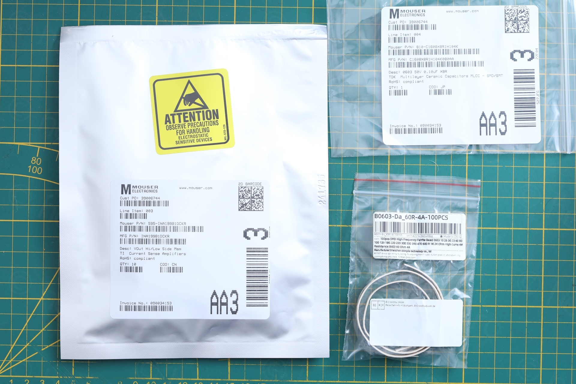
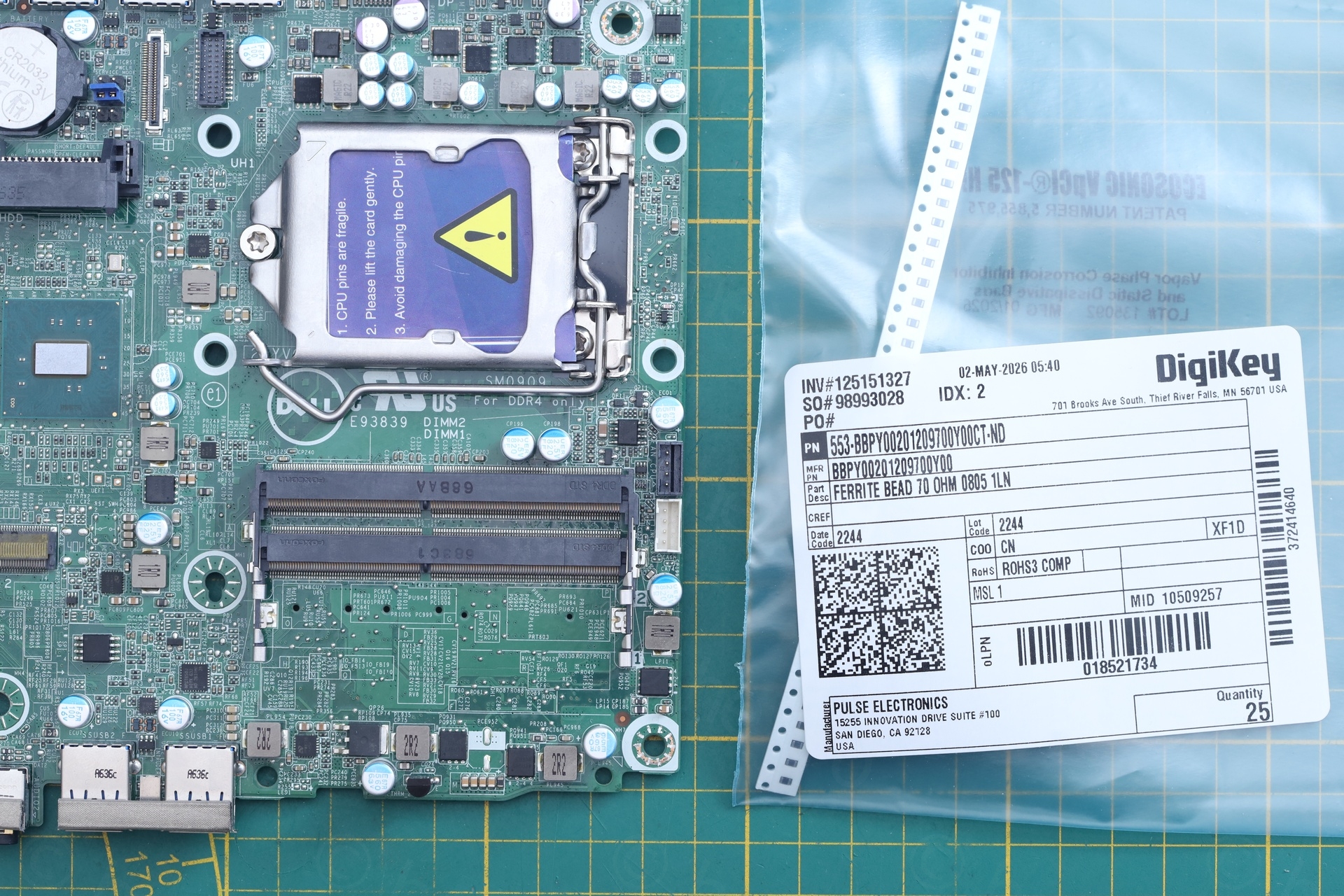
It turns out I needed 0805 size, one size up. At this size I was able to find the correct ones, 70 Ω @ 100 MHz and 3 A, Mfr. No: BBPY00201209700Y00. At least I was able to test before the right ones arrived!
The blown capacitor was also a little tricky. I decided to go with 0.1 uF @ 50 V size 0603. As neither of the schematics mention the size, this one I to measure. Mfr. No: C1608X8R1H104K080AA
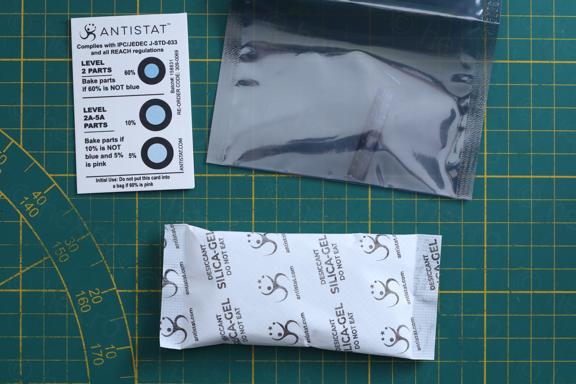
Was impressed by the packaging for the INA199 … hermetic anti-static bag, large bag of silica gel against moisture, humidity indicator. Excellent stuff.
Fixing
Fix was to replace the three identified components.
I made a mistake by not using low melt solder (or hot air gun) when de-soldering the INA199 IC. It was so small, I thought I could de-solder it using the hot tweezers I used for the other two components. At 480 °C, the tweezers were not able to transfer enough heat – but I managed to scorch the motherboard. I covered the little mark with some UV solder mask.
And last, the little capacitor next to INA199 is already in the photos above.
Testing was just trying to play with Power Management in Windows and see the speed working correctly for the Intel i5-6500T CPU:
Putting it back together is rather easy – with the old hard disk holding Proxmox:
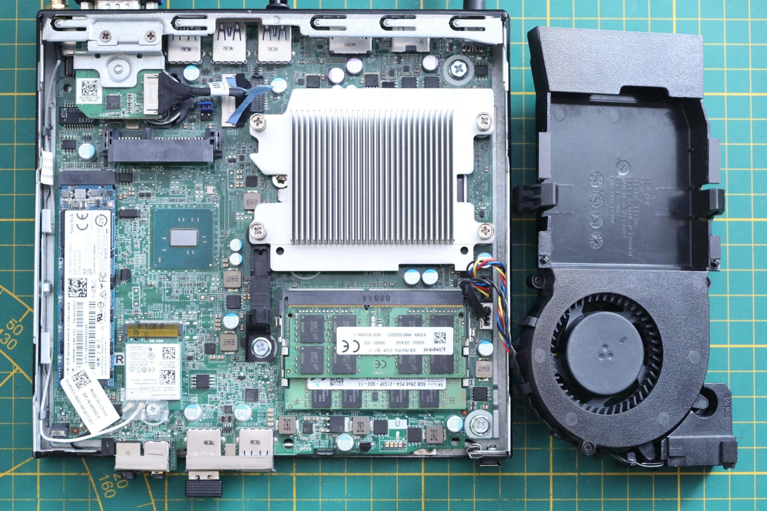
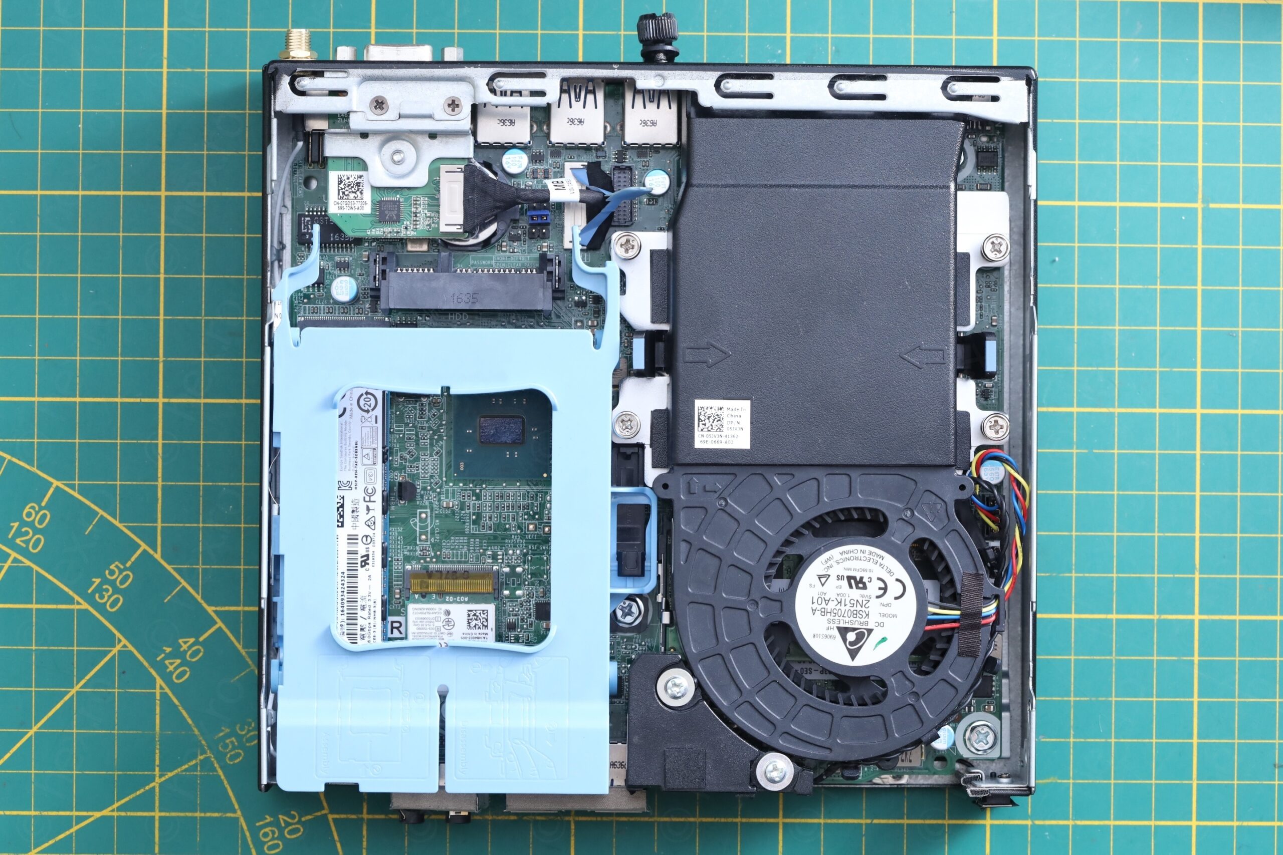
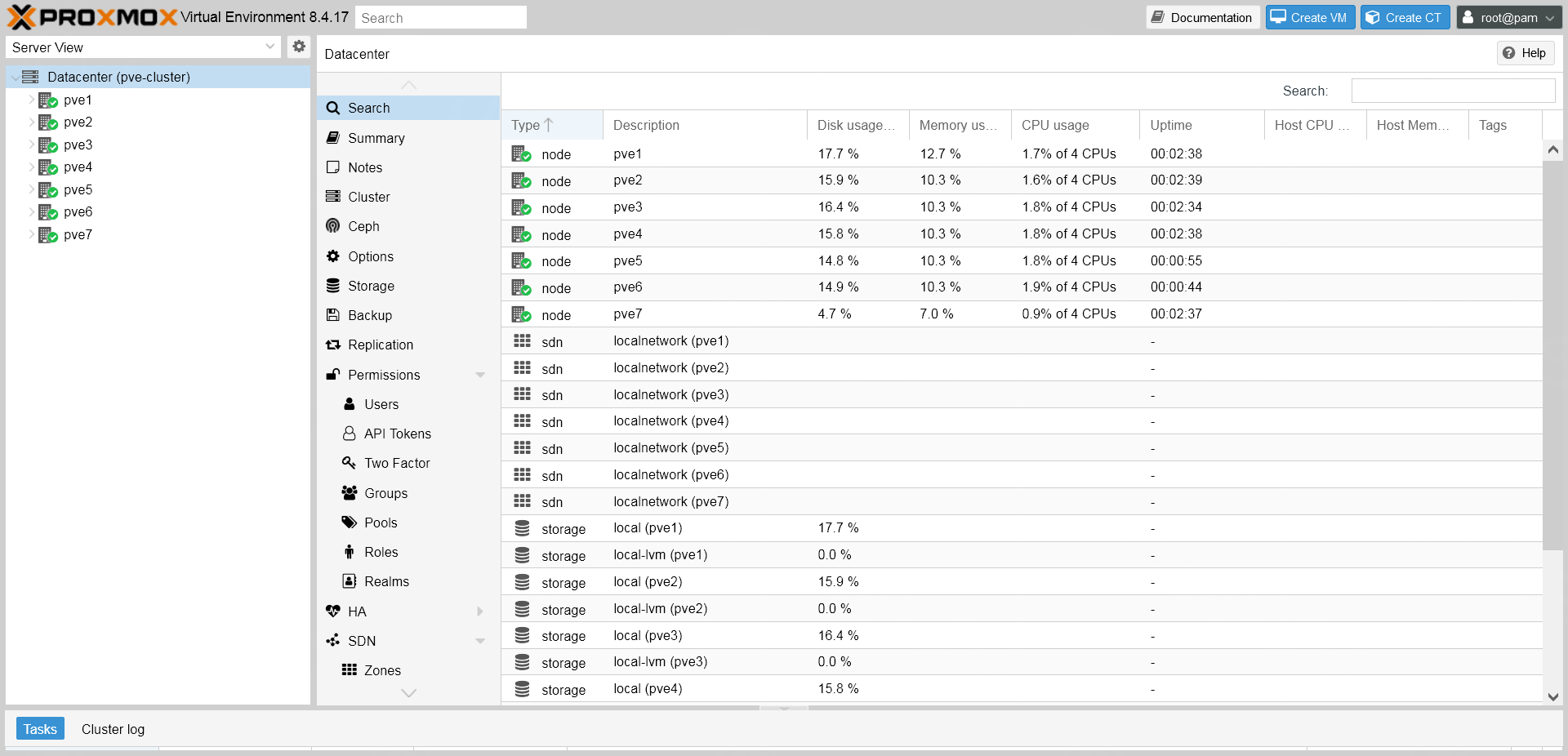
And it was added into the stash (it is pve3 below). Beforehand, its CPU was always reported at higher usage (around 4%) – but now is aligned with the others – except pve7 which is a different / faster Micro PC.
I need to find a better cooling solution for the small stash of PCs, but this will come once I start to heavily use them.
In conclusion, the current shunt amplifier (INA199) was not working properly and had the output stuck to 1.34 V (much higher than a normal 0.2 V for example). The motherboard has some logic to convert this voltage into the equivalent power consumption. With a constant high voltage, motherboard was considering that a 65 W charger was not able to provide sufficient power. Thus the throttling down of the CPU to 800 MHz. It still worked fine with 90 W charger because most likely, it assumes that 90 W would provide enough power to handle that “fake” consumption reported by the bad INA199. After replacing it, the PC works fine with its intended 65 W charger.
Leave a Reply