
Table of Contents
- Introduction
- The insides
- Repairs
- Custom RF Adapter for Sony FD-40
- 3D Printed Adjustment Knobs
- Calibration
- Conclusion
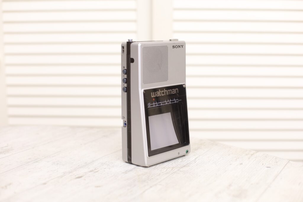
Introduction
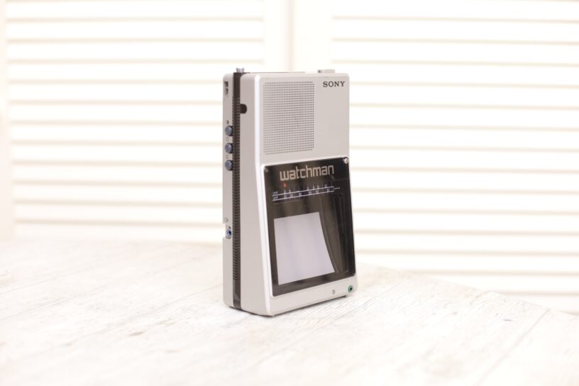
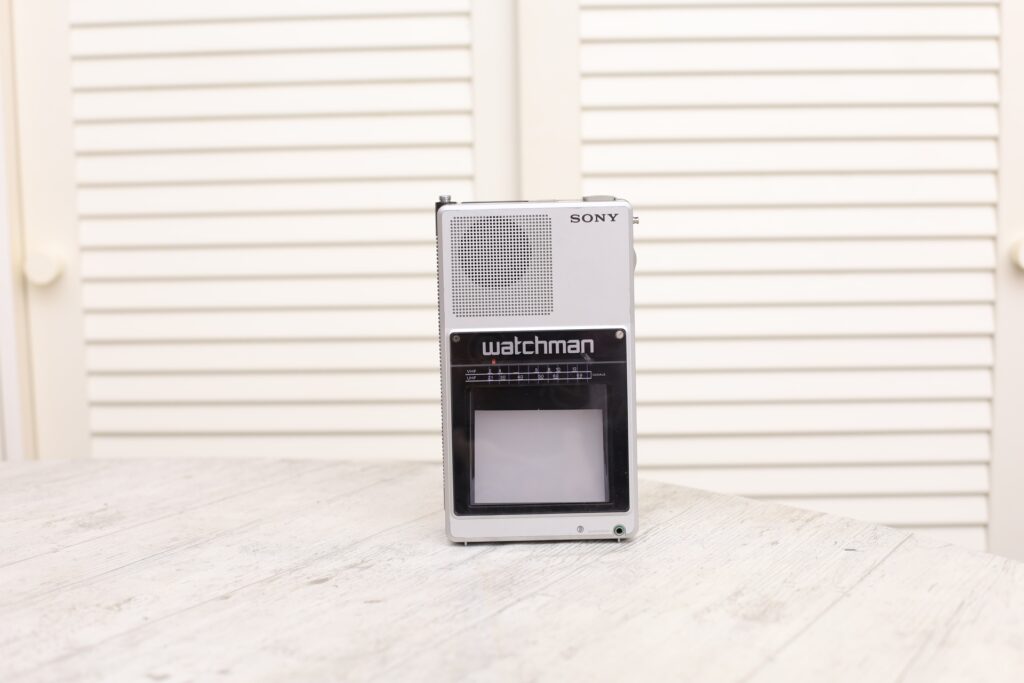
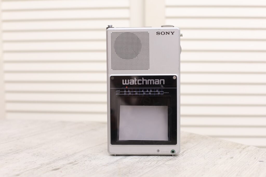
I found it listed as faulty on EBay with a good price. Figured it could be fun to try to repair it. It arrived a week after:
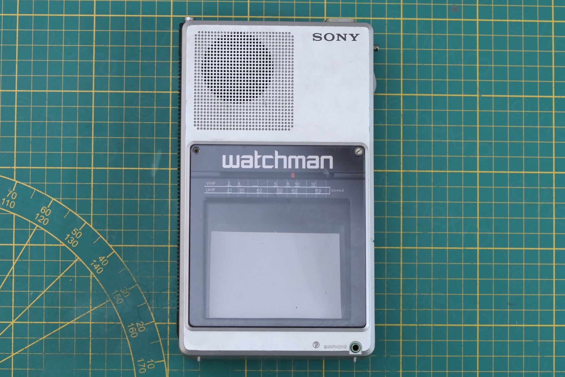
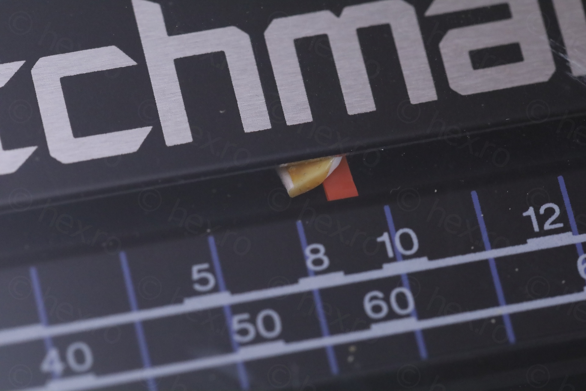
On a closer look – only the brightness knob was still present. The Video IN jack was “off-center”. A dislodged piece of white plastic bit was stuck in between the dial pointer and the see through lens.
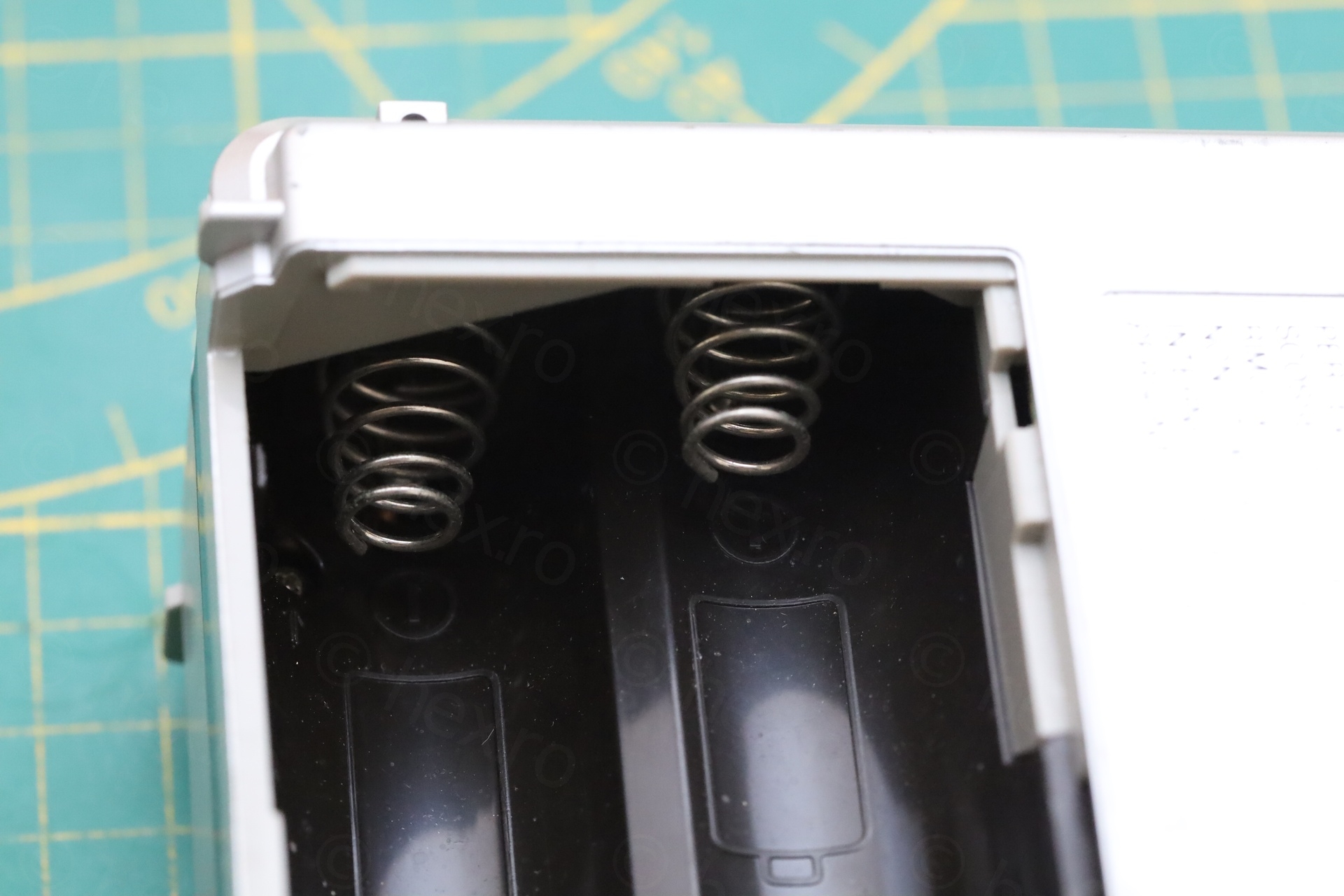
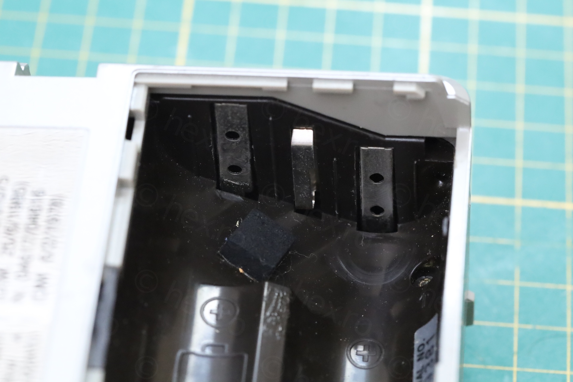
A glimmer of hope: the battery compartment had no traces of corrosion.
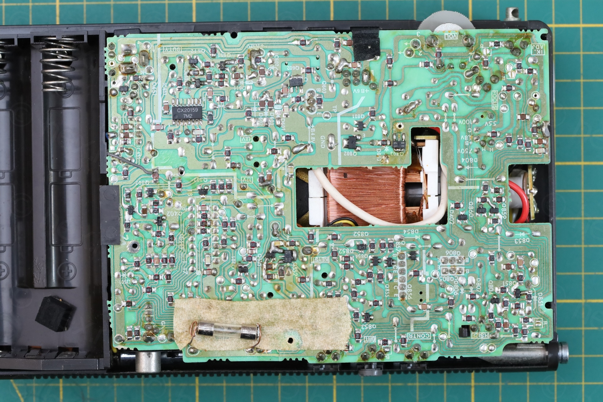
The insides
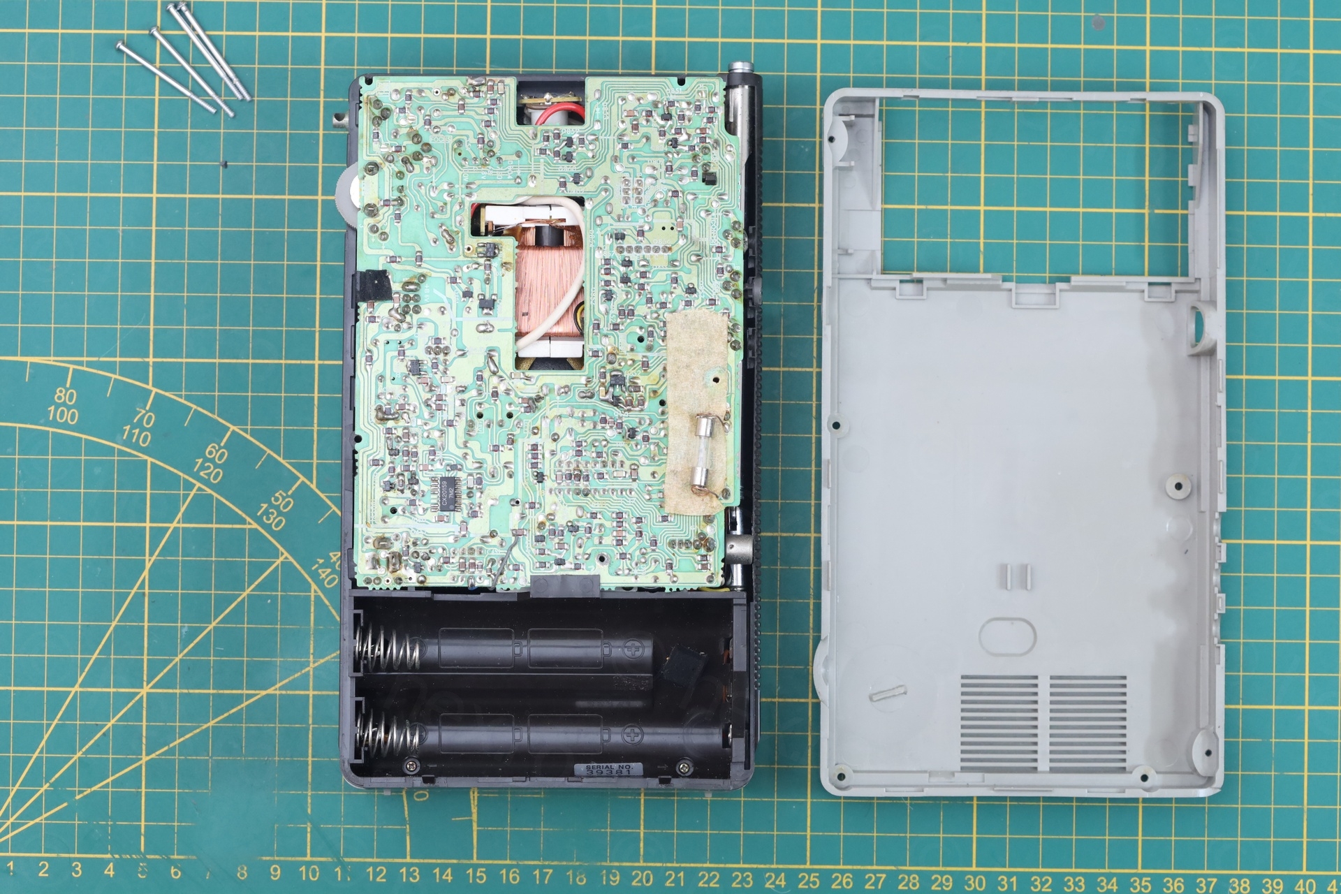
Taking it apart was easy, but the findings were infuriating.
This content refers to cathode ray tube (CRT) equipment which may contain components operating at high voltage.
Hazardous voltages may remain present even after the equipment has been disconnected from the mains supply. Improper handling may present a risk of electric shock.
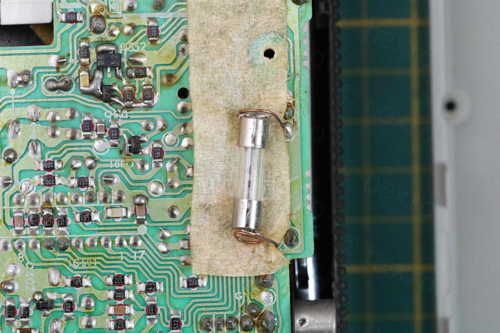
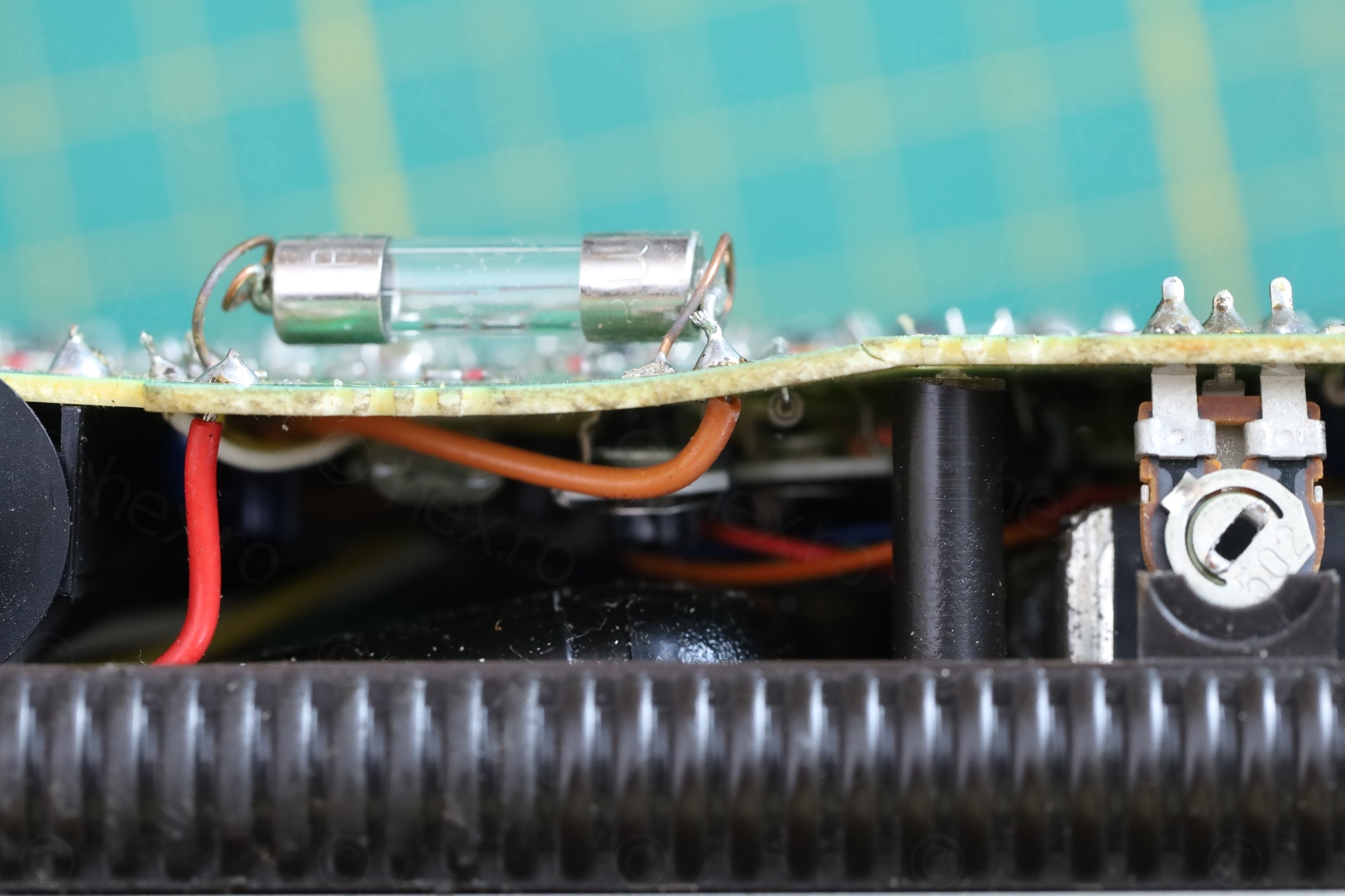
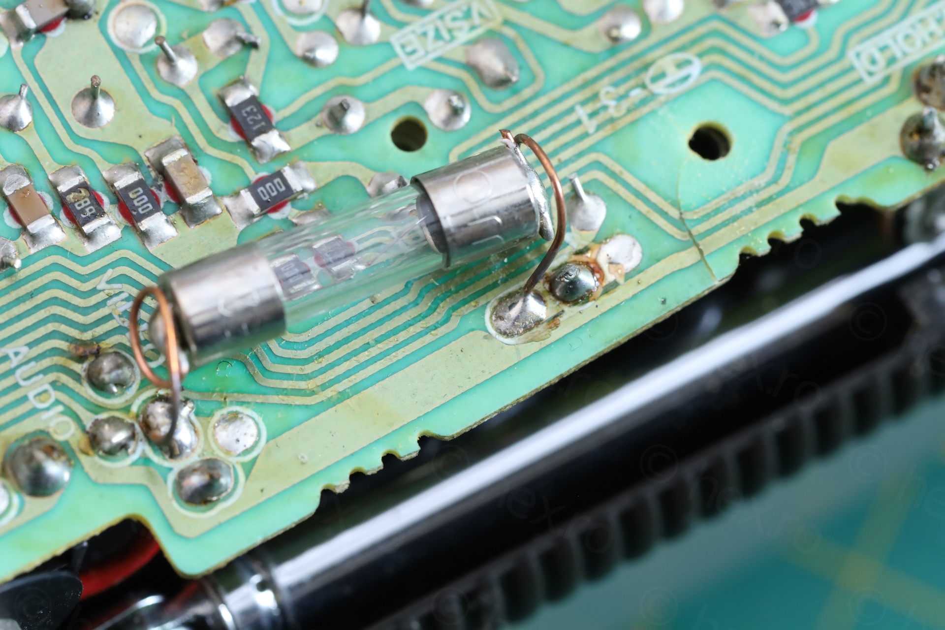
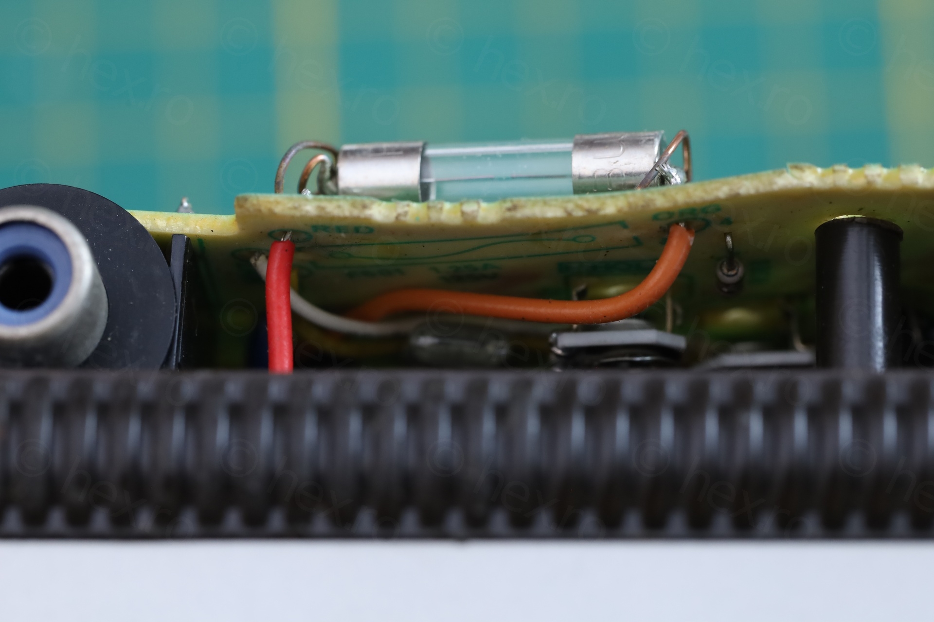
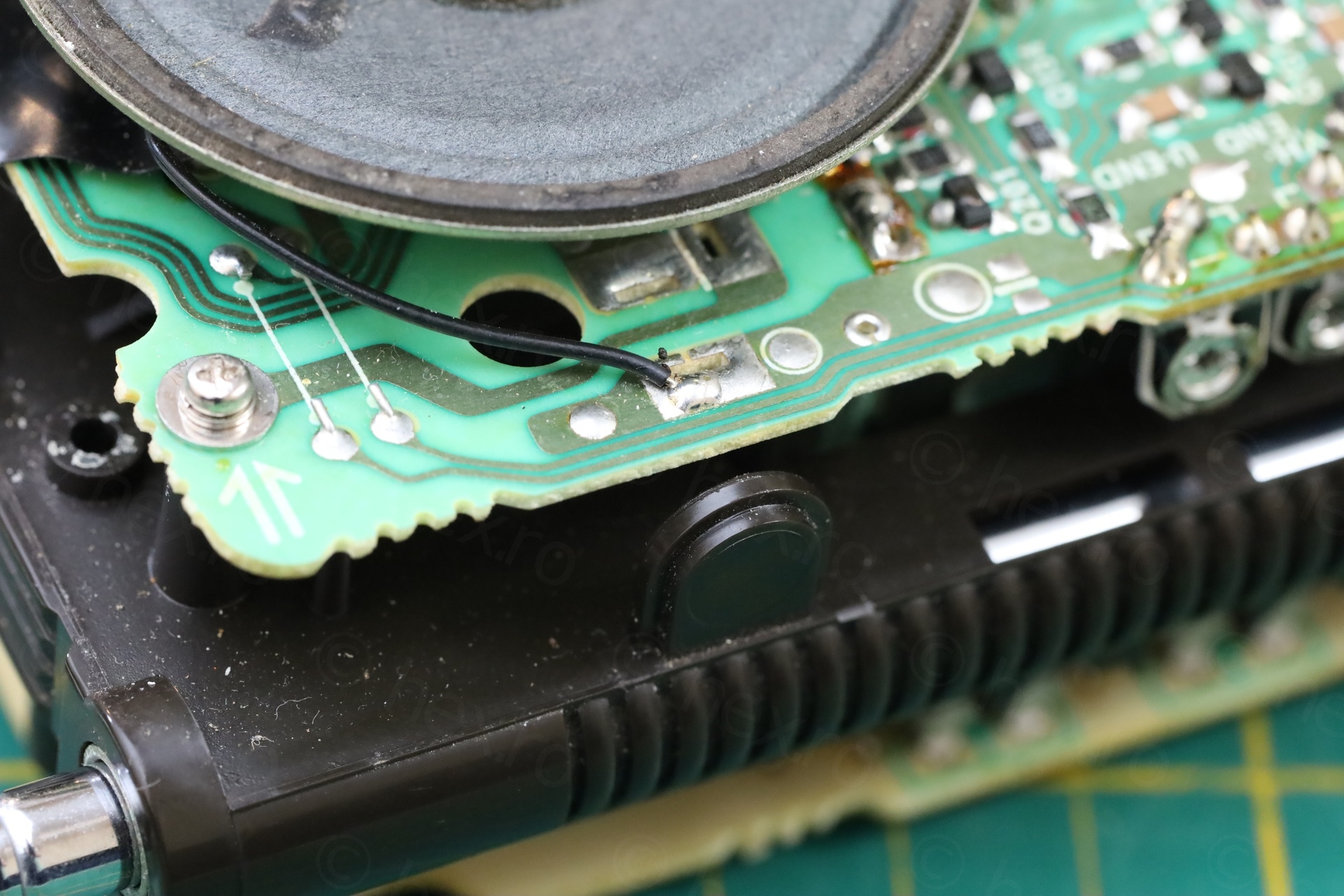
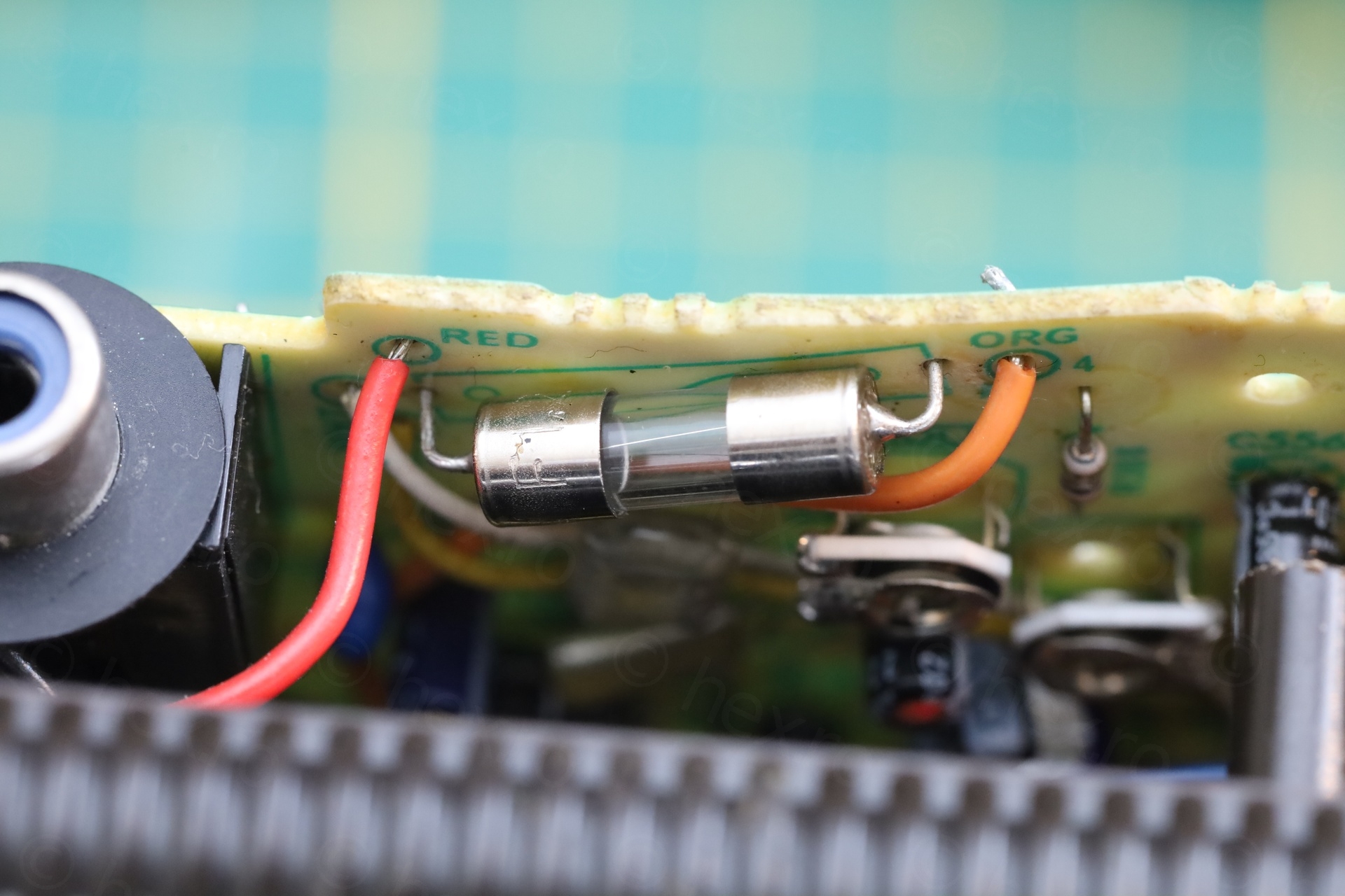
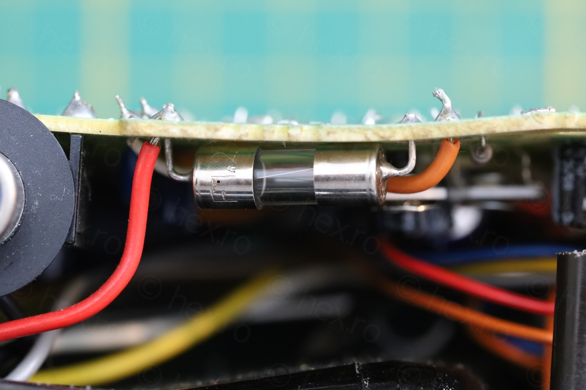
Botched fuse installation
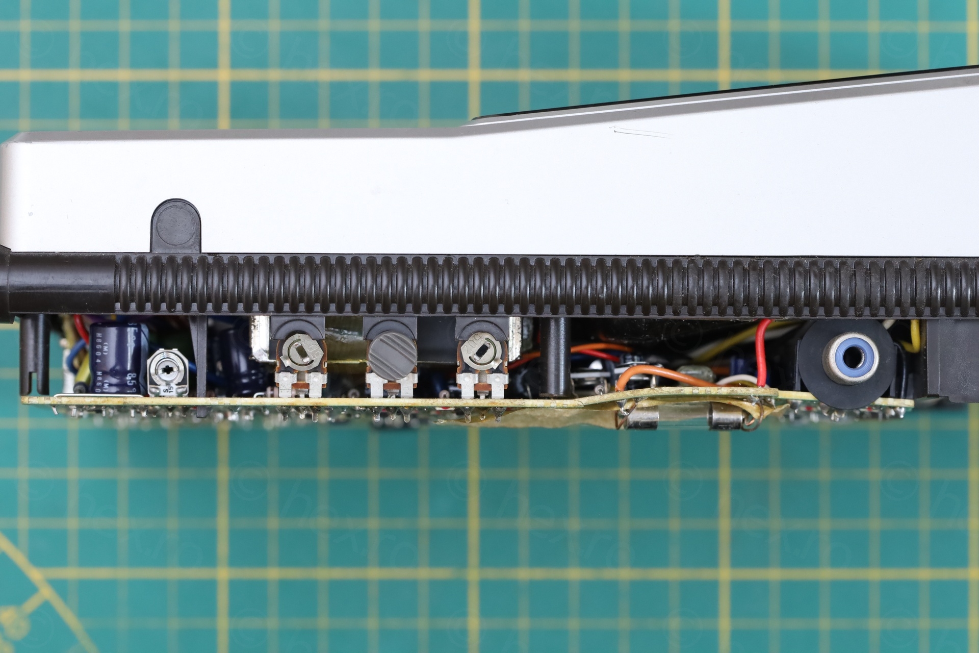
The fuse was installed on the wrong side of the circuit board:
This would not be a problem in itself, however, the circuit board underneath was cracked. Some traces were cut:
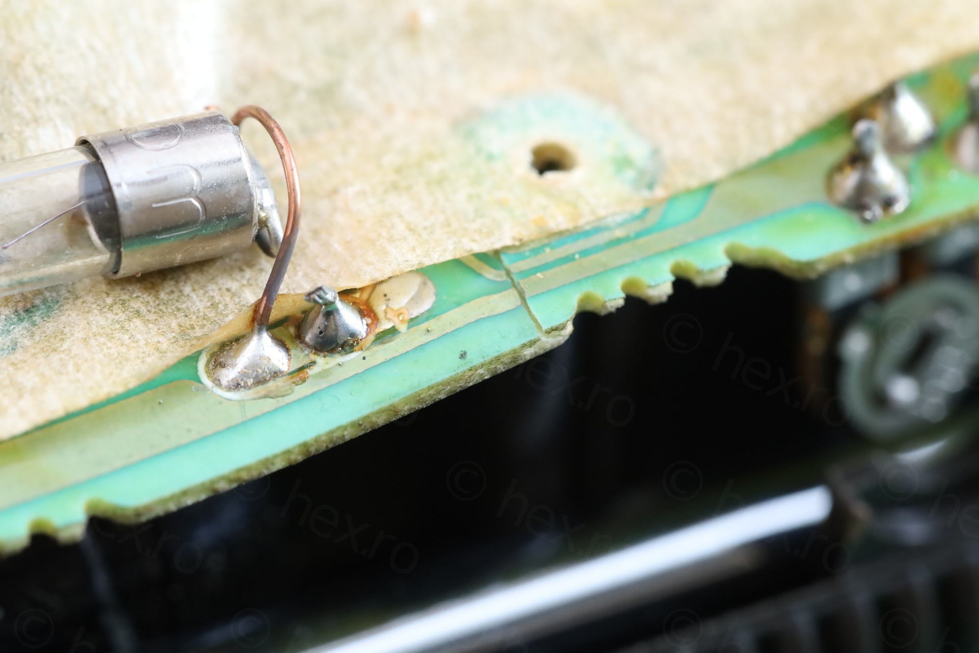
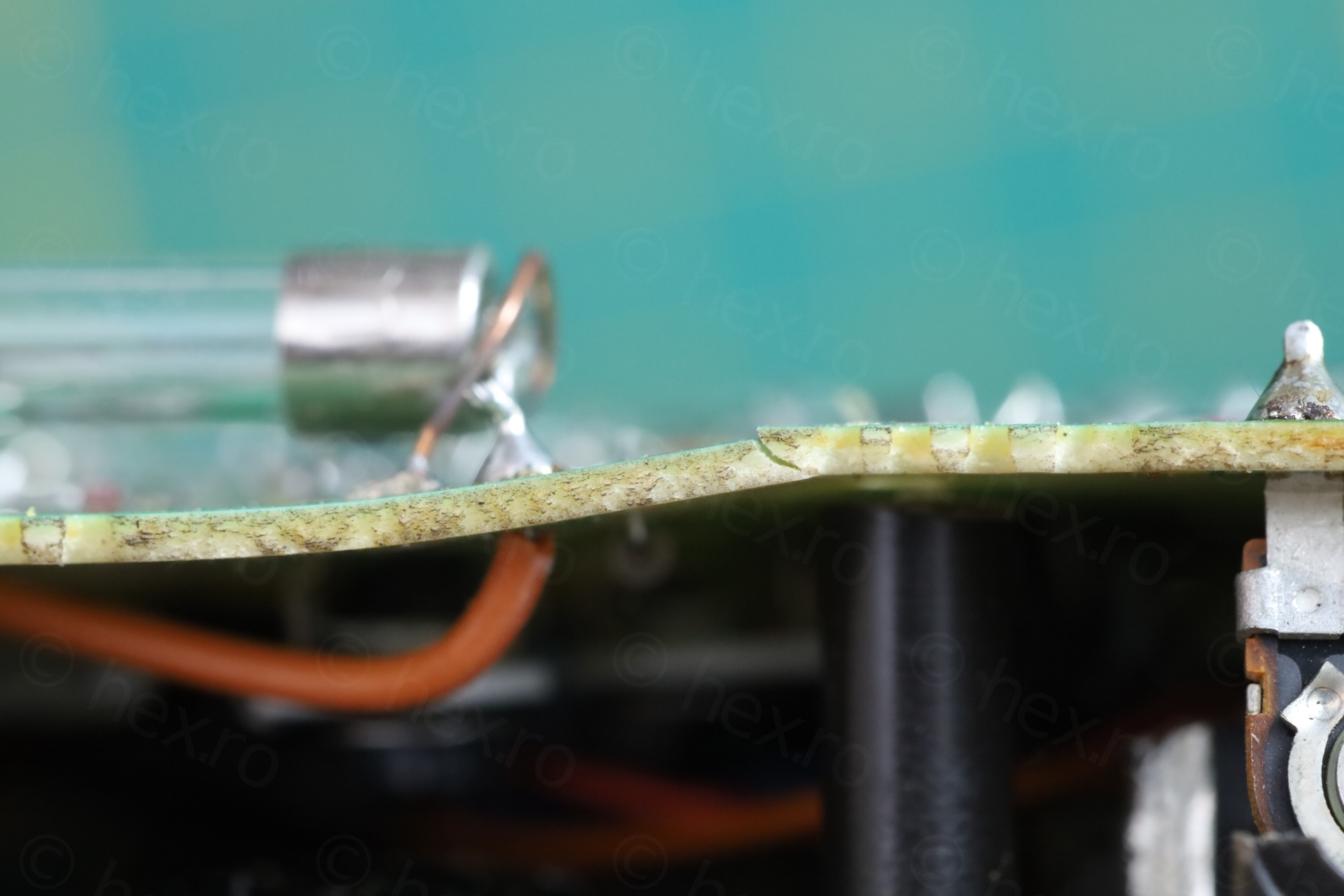
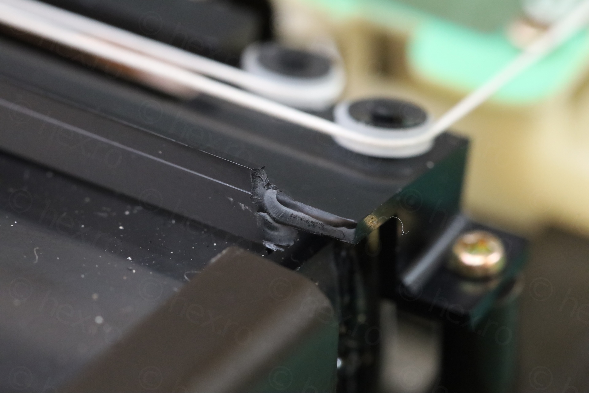
Very close to this area, the Video IN jack is present, but the circuit board was so bent – it got the Video IN jack out of alignment with the external case.
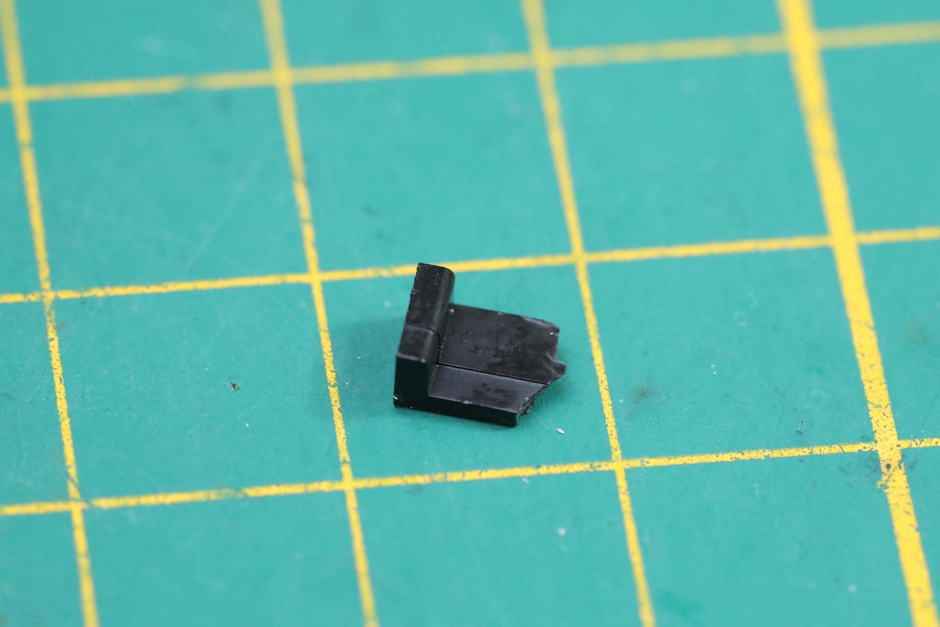
Cracked bits and pieces
While taking it apart, some bits and pieces fell out:
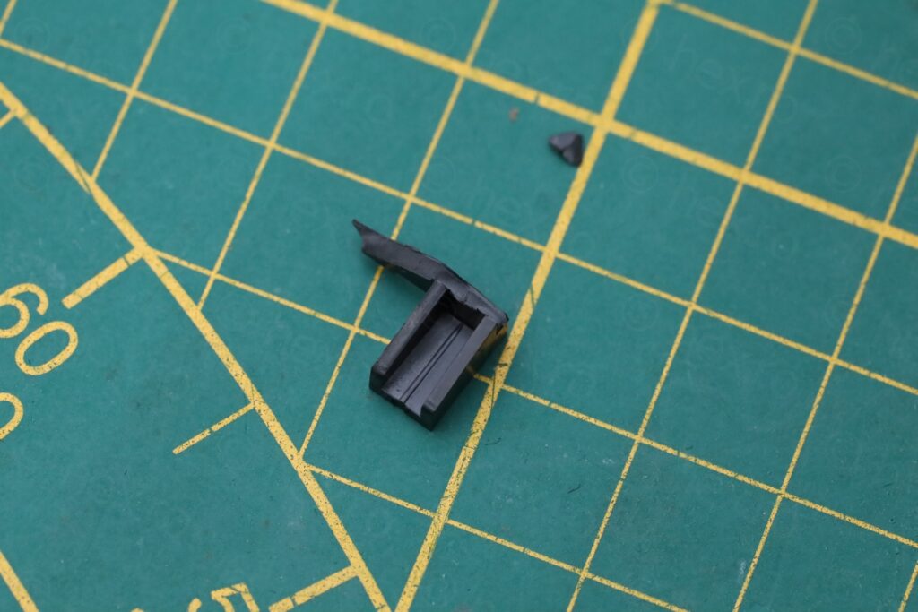
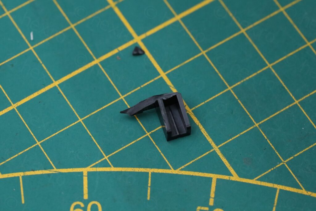
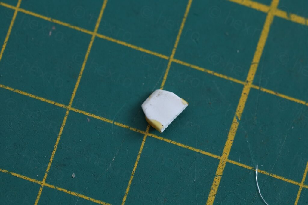
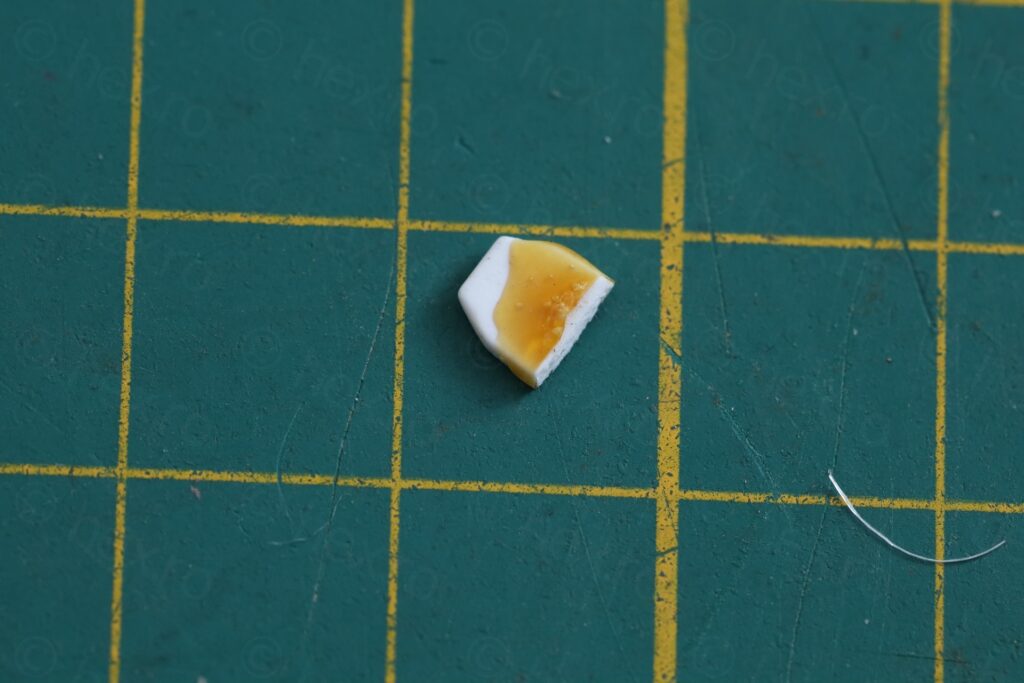
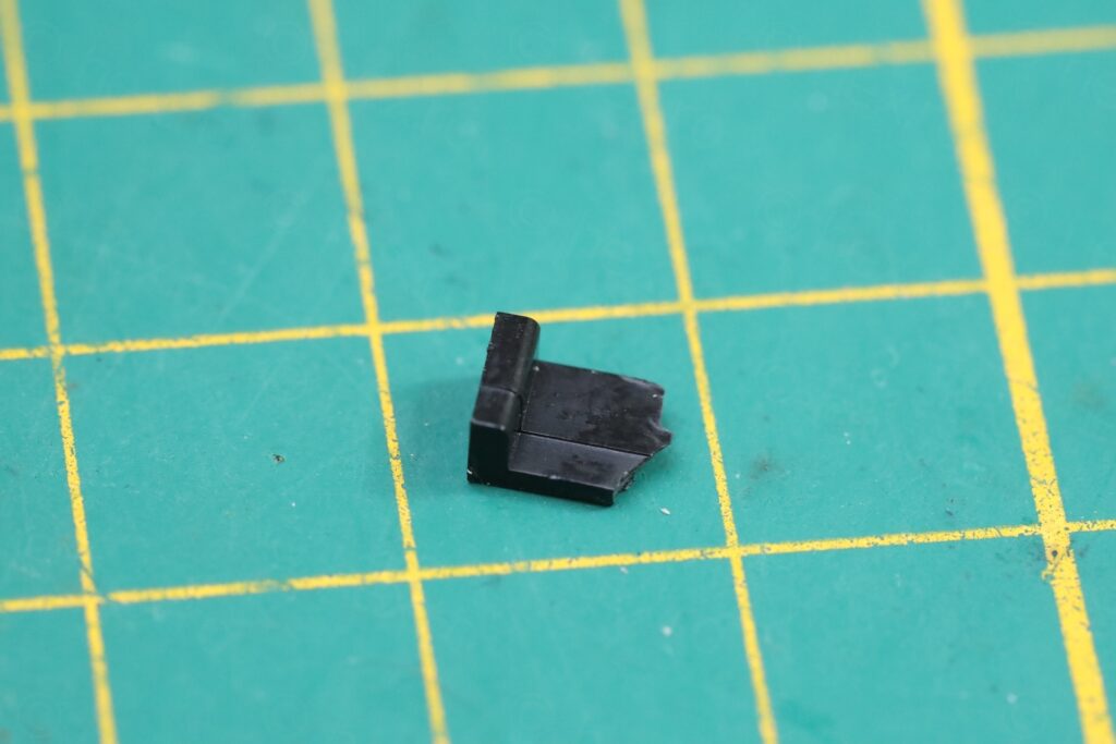

I thought that the case was forced down onto the fuse, cracking the board – but I have a hard time imagining somebody going through the pain of re-soldering a fuse but not paying attention when putting the case back. Most likely this thing was dropped some time after the fuse was installed.
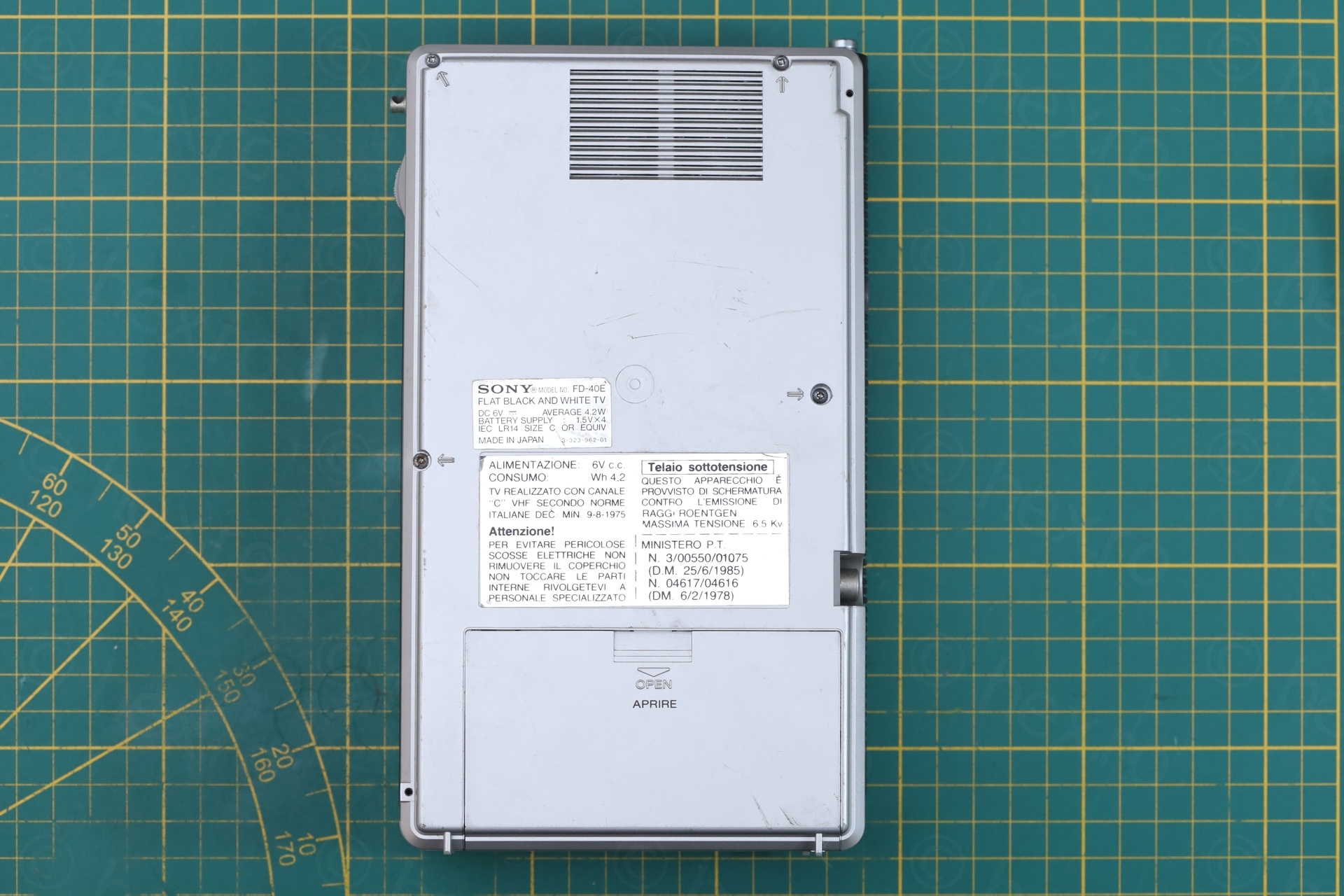
No Antenna Input Jack
Surprisingly, the Sony FD-40E TV does not have an TV Antenna input jack, even if it seems to be the only one like this. All the other Sony FD-40 TVs seem to have it, except this one that has a plastic mask and no jack installed:
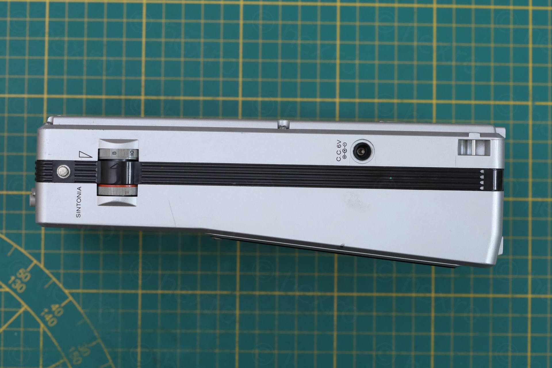
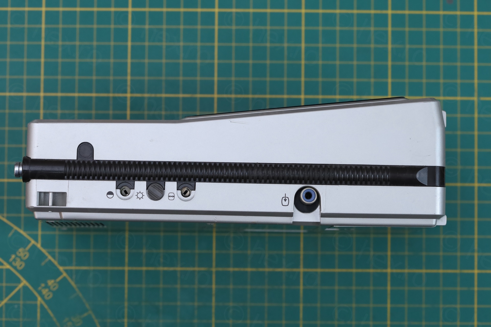
One last problem I noticed was that the tuning dial was … scratchy. Towards the end of the scale it was difficult to move.
Repairs
I’ve configured power supply to 6V, 250mA limit -> but voltage dropped to 1.5V when turning the TV on. I upped the current limit to 500mA -> voltage was still very low. So there was a short somewhere..
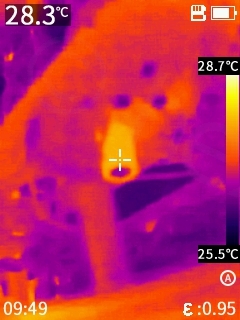
I had a look with the thermal camera, and the green transistor Q603 was getting very hot:
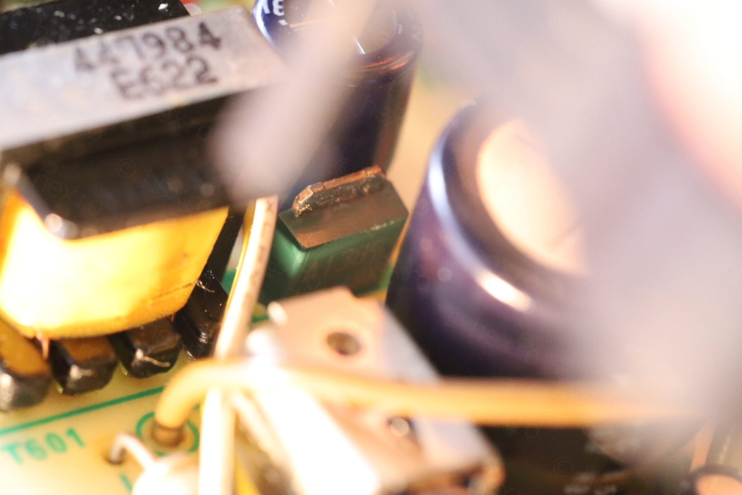
The schematic shows that Q603’s Collector is connected to C607 which, when measured with the ESR meter, appears to have 0.13ohms ESR (and is reported in circuit / shorted). The problem is that the 4.8V line that C607 is connected to has many other components on it. Not sure if C607 is culprit. So I would have to put some voltage on that line to see what gets hot.
I have applied 4.8V to the Collector of Q603 with 300mA limit, then with 900mA limit as nothing was getting hot. I assumed it is a large component. Out of frustration, I upped the limit to 2A and finally, I saw a faint glow coming out of C607 … it was it all the way.
Thankfully I caught it glowing. As I was applying the 2A, the short vanished and line started drawing 0.360mA and voltage went back up to 4.8V.
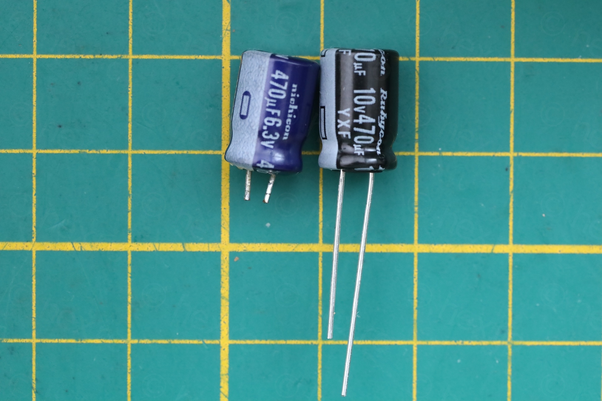
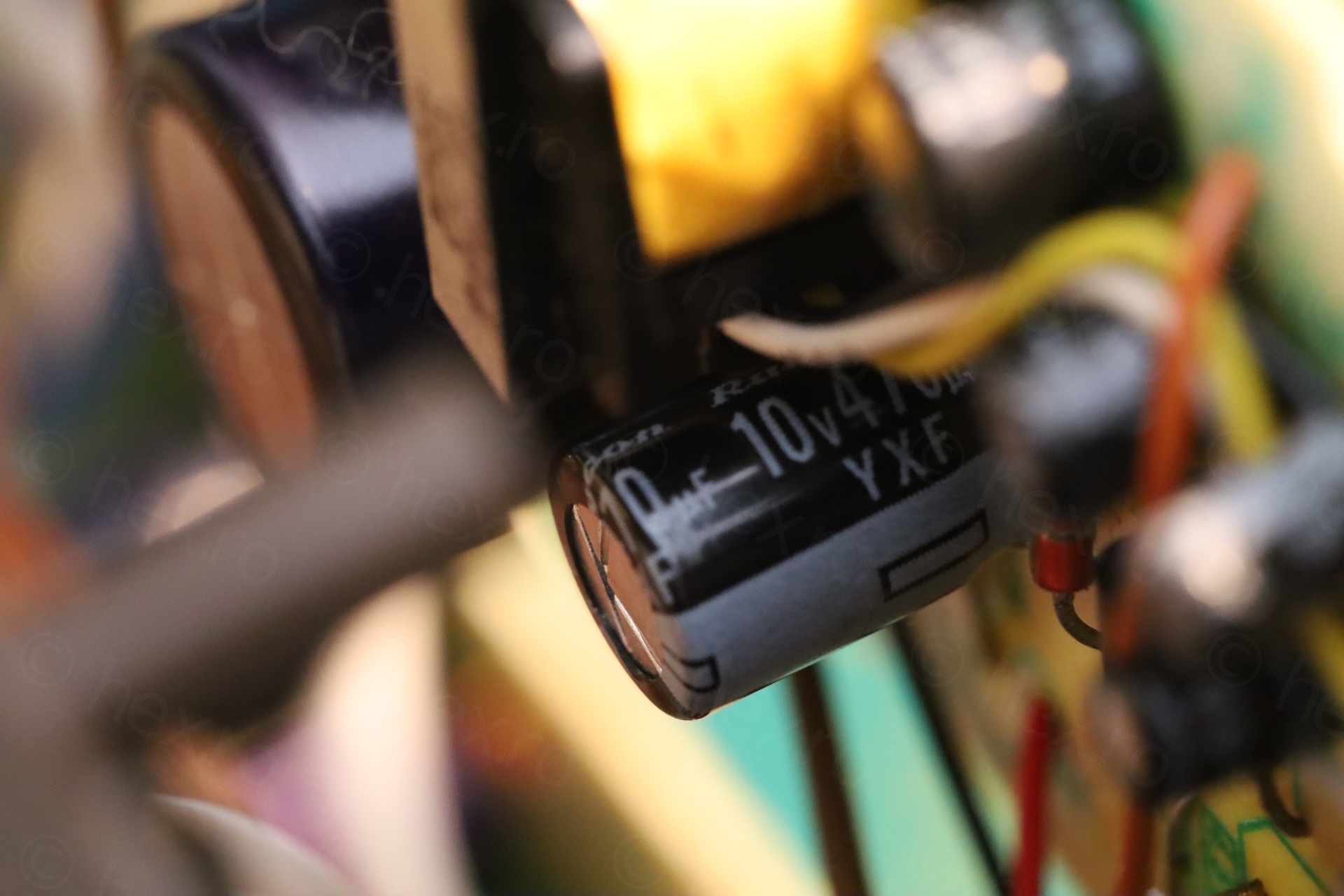
Replace shorted C607
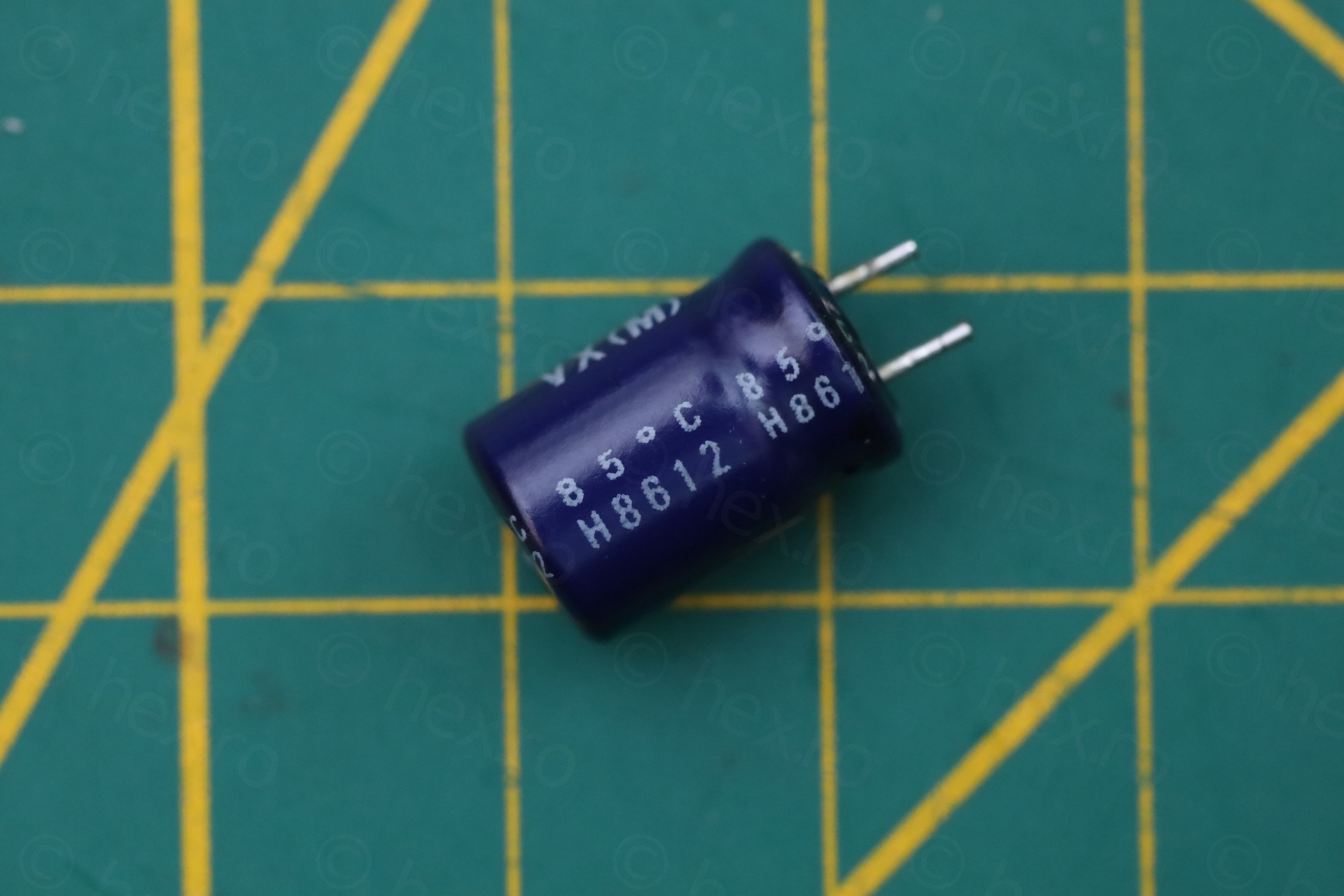
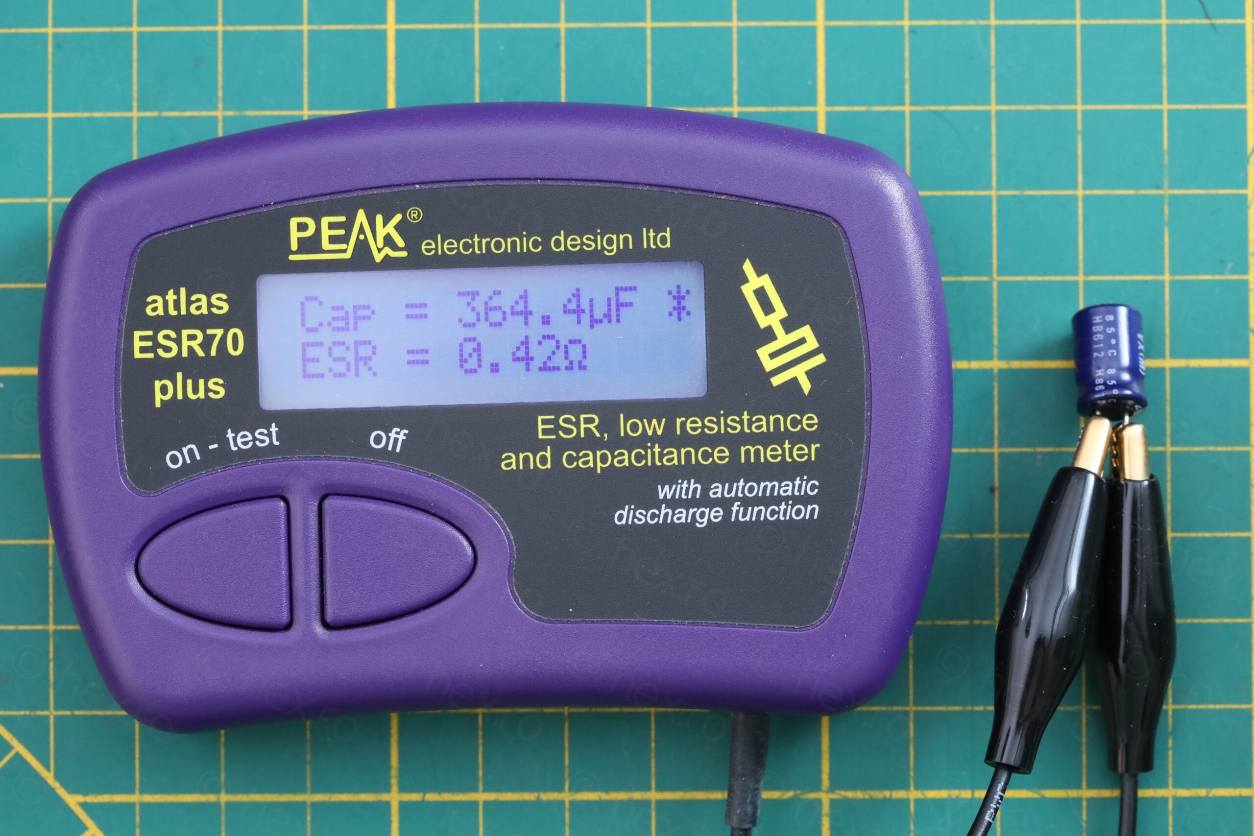
The capacitor is from a reputable brand – and, not surprisingly, after the short went away, it was now showing good ESR, albeit at a lower capacity (364µF vs 470µF). I replaced it with another reputable brand capacitor that I had. The replacement is rated for 6000hours @ 105 °C so it should endure better the heat from Q603 than the old one which was rated at 85 °C:
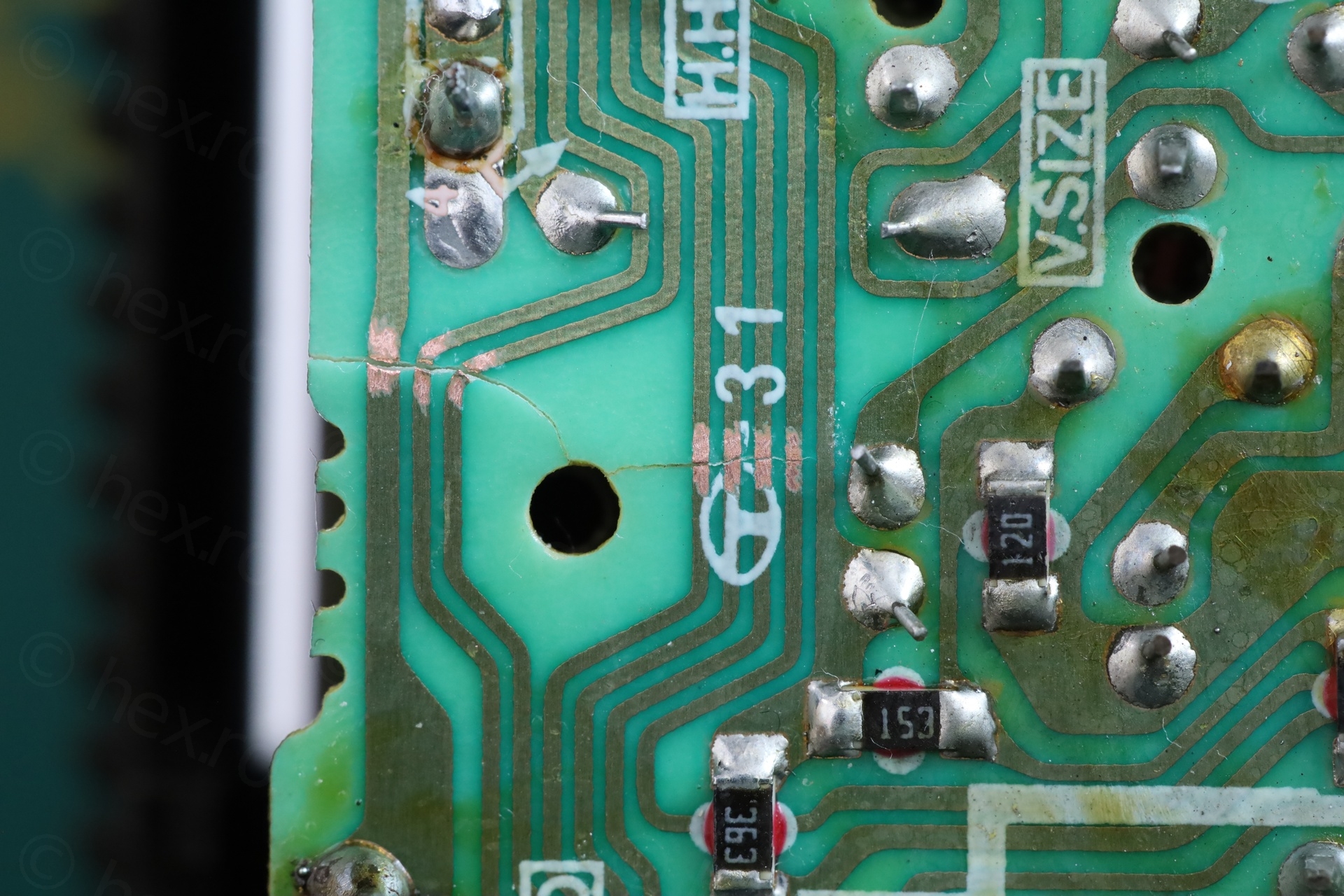
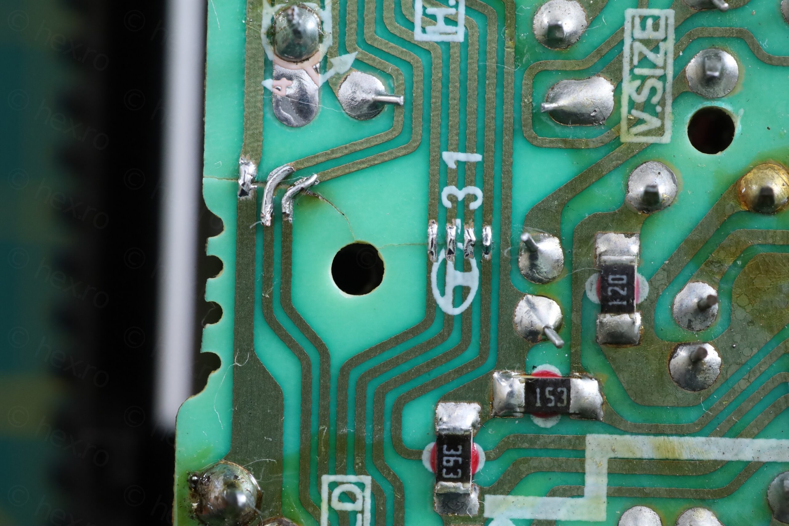
After this, more components are shown “hot”, but the worst is a resistor marked 120 next to the T-31 logo (close to the place where tracks are broken).
It turns out to be R557 / 12 ohms resistor. R557 is part of the vertical deflection circuitry.
Having a look around, it looked complicated why it would draw such a large current. Too many leads to explore. On the other hand, no sign of life on the CRT, and I’m wondering if having so many cracked traces isn’t in fact now creating more problems diagnosing the issues.
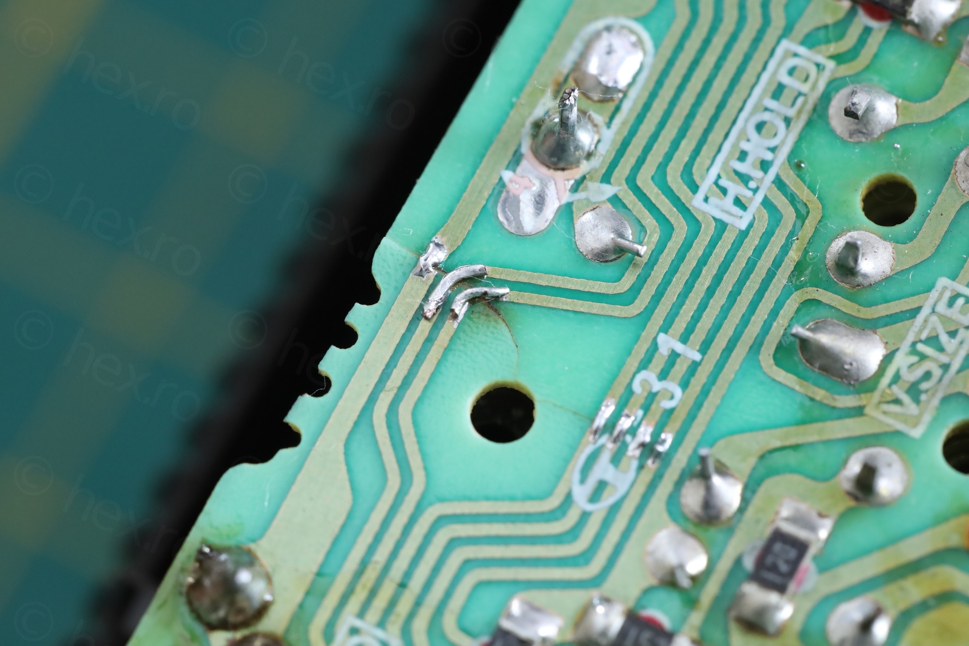
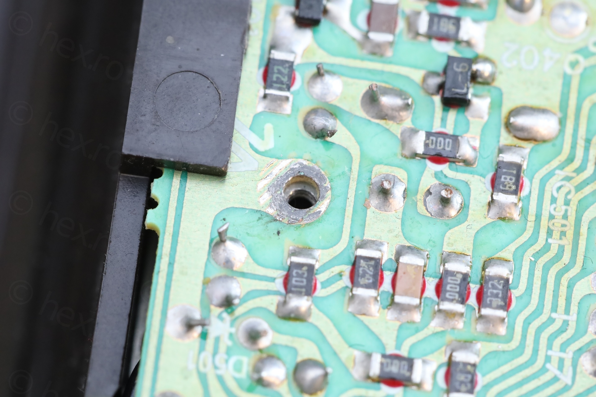
Bridging the gaps
Restoring the cut traces involved scraping a bit the coating to reach to copper and bridging the gaps. For two of the traces I had to use some small piece of wire, as I had difficulties creating the solder bridge:
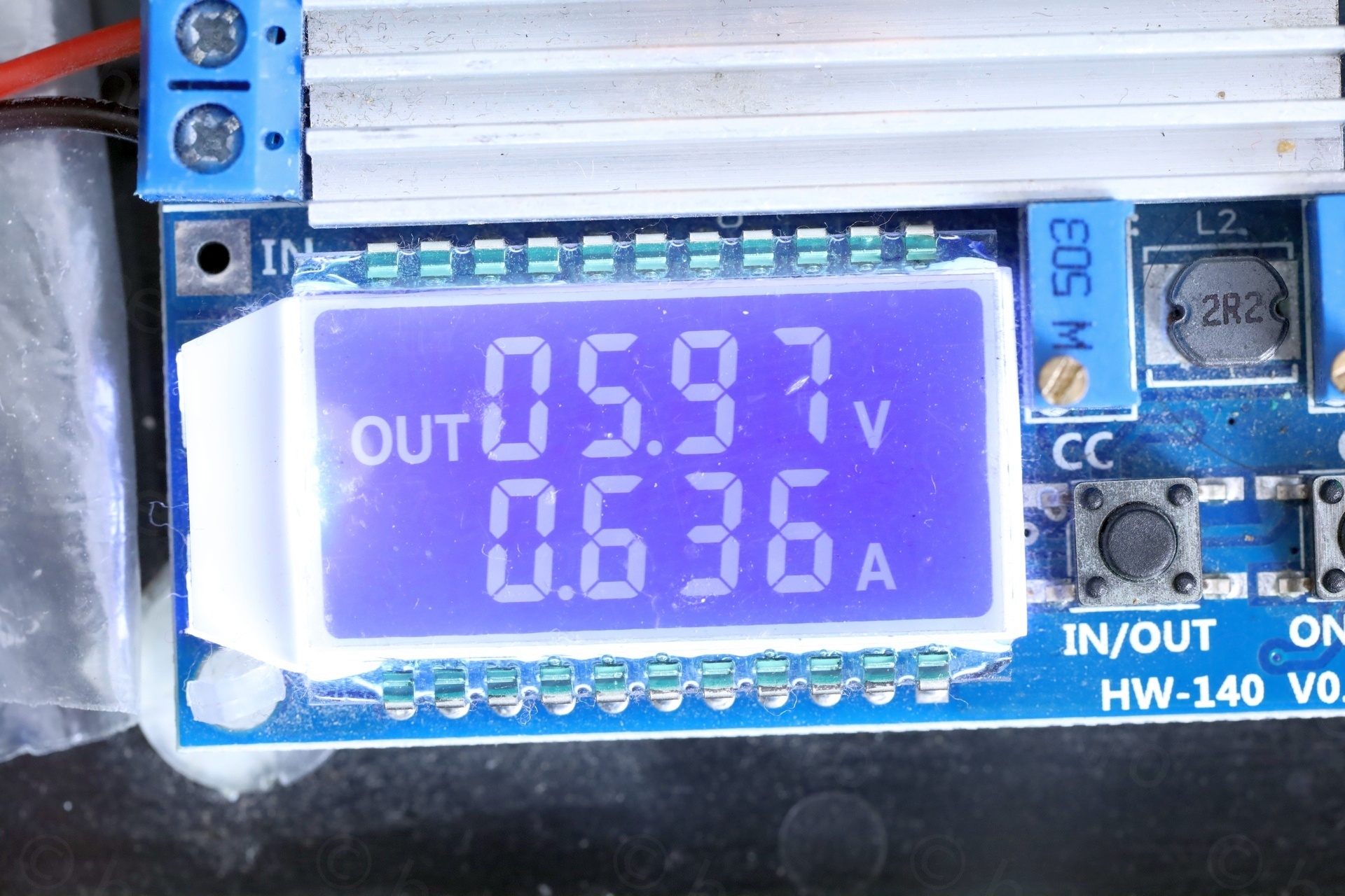
After these fixes, the CRT sprang back to life :). The machinery was drawing 0.63A at 6V:
Plastic pieces
I couldn’t find all the places from where the plastic pieces snapped from .. I did look thoroughly, to the point where I questioned if they came from the TV itself. I glued one corner plastic:
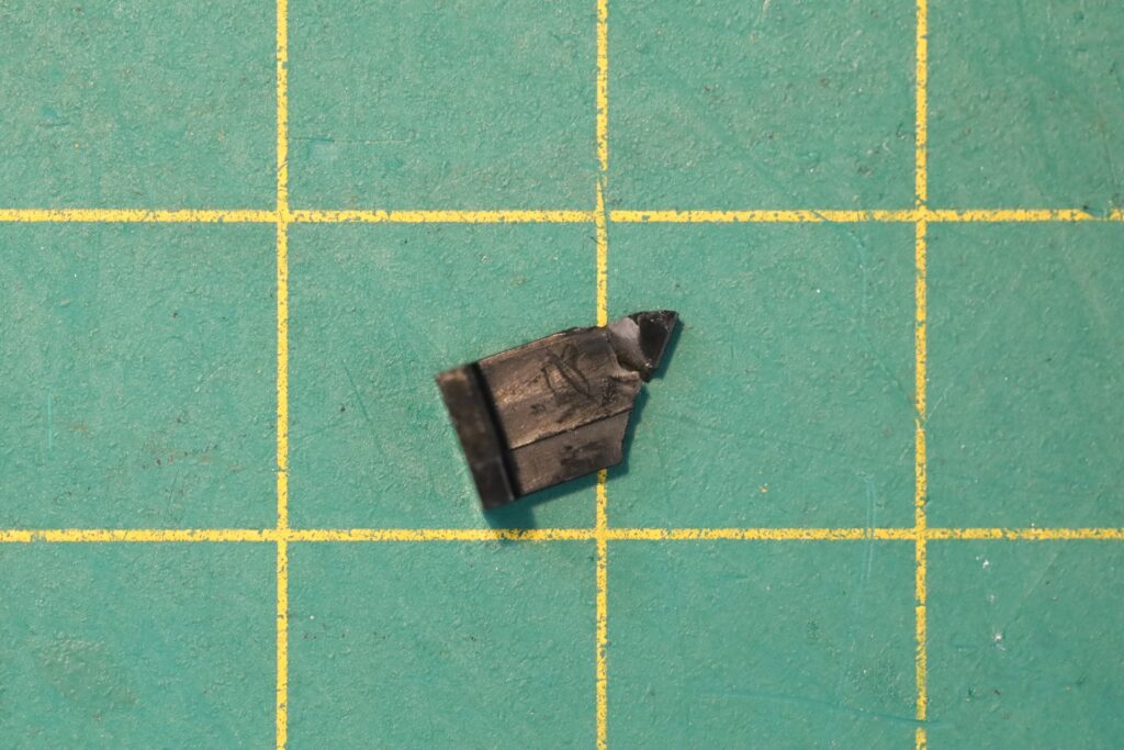
I kept the parts. If, in the future, I have to open the TV again, maybe I’ll spot where they come from.
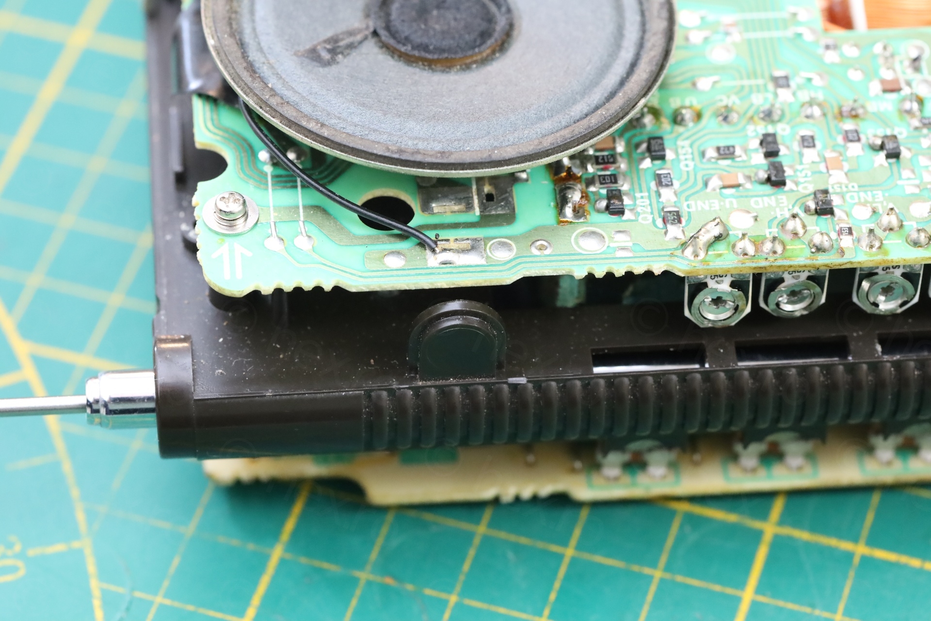
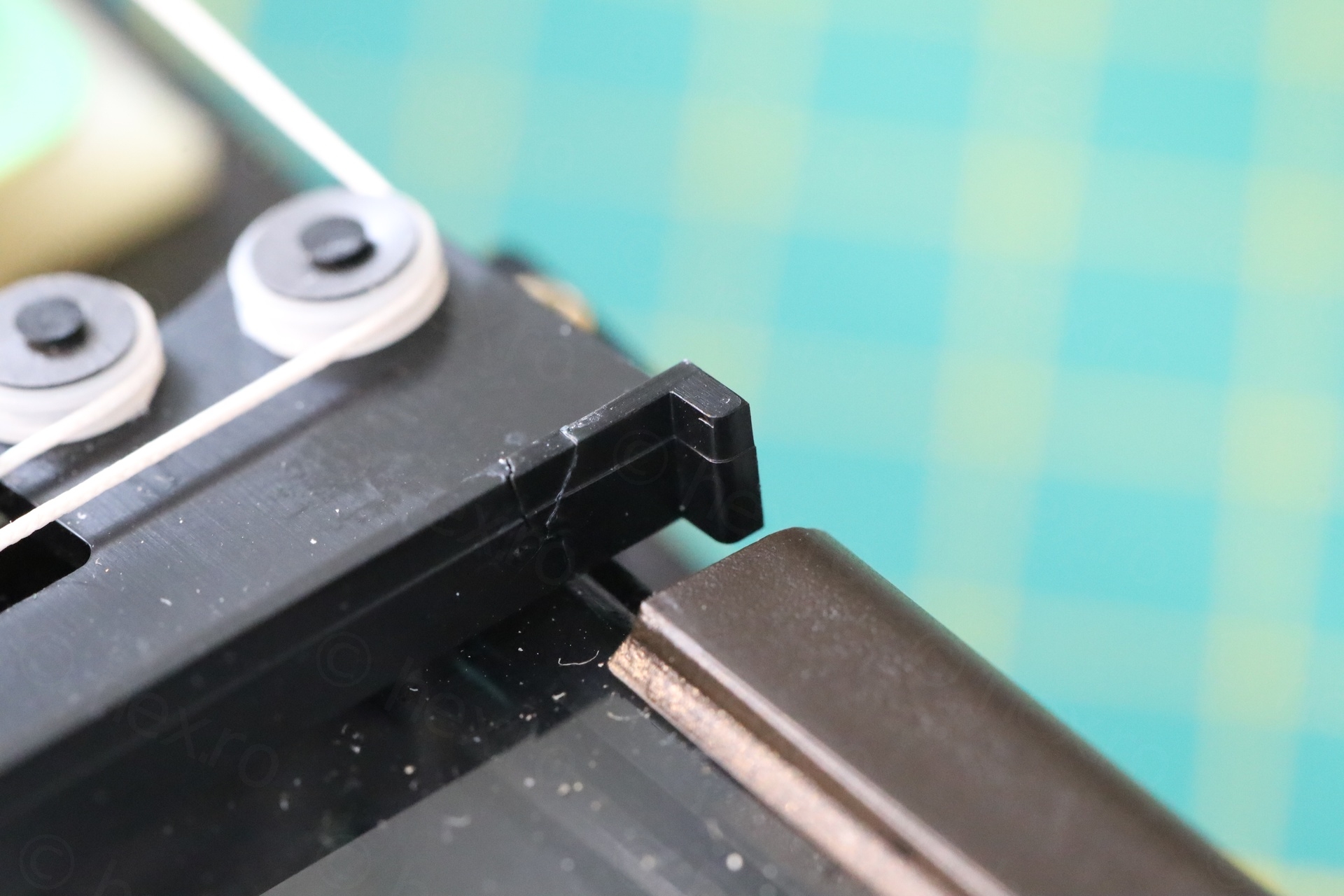
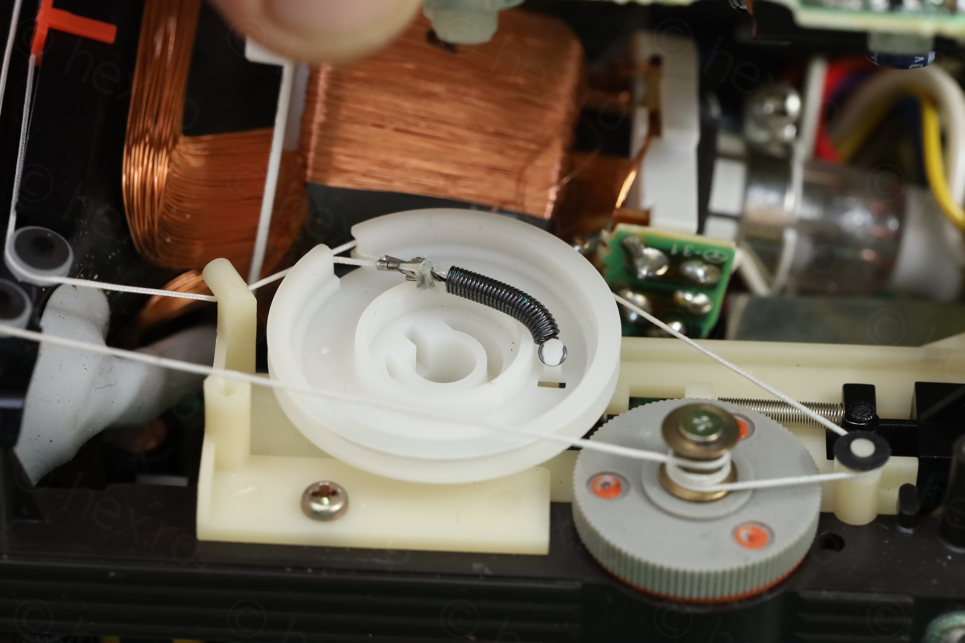
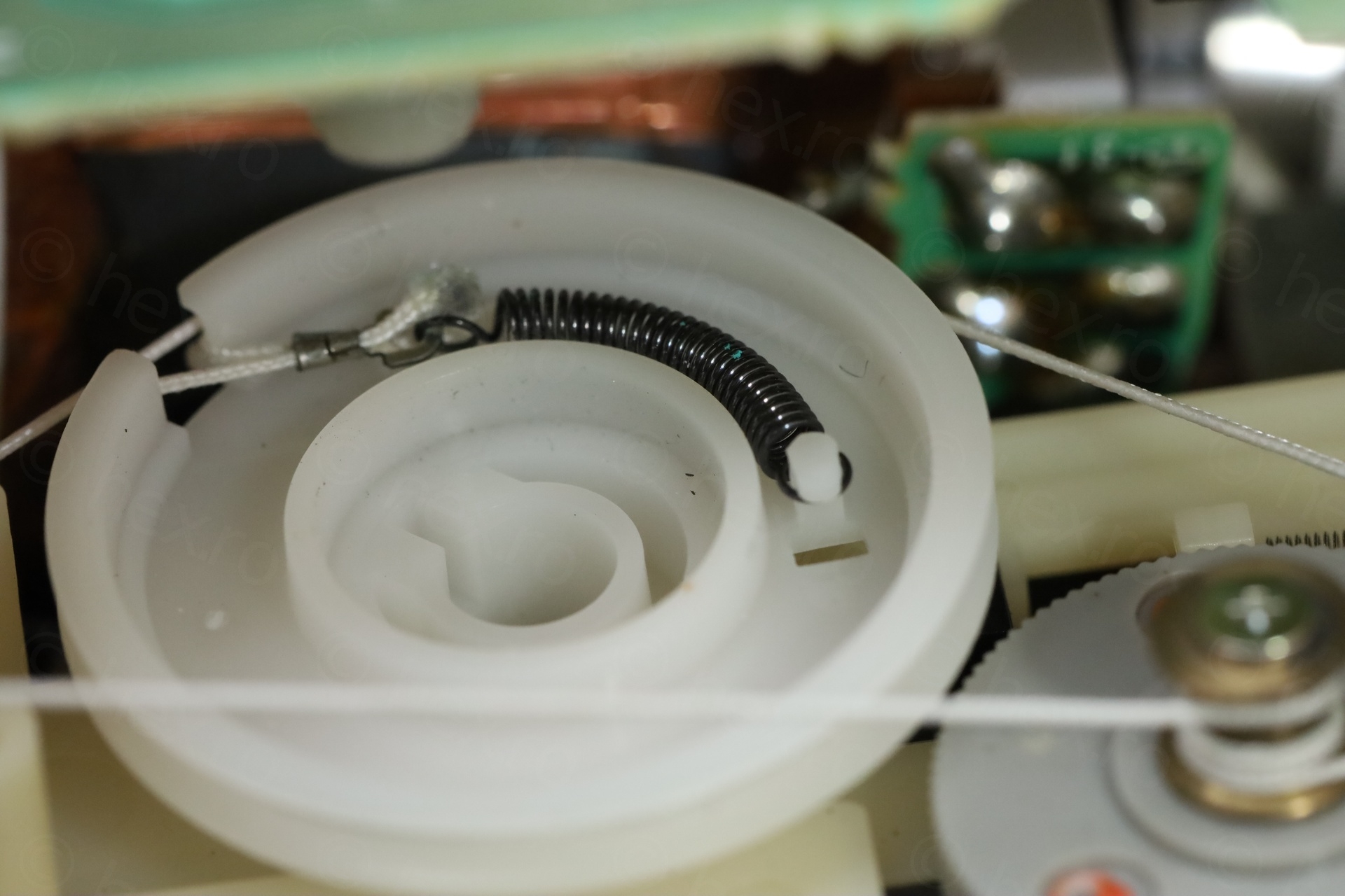
Scratchy tuning pot
The scratchy tuning pot was due to the spring that jumped from its place when the TV fell. After having reseated, all was fine and no more scratching against the top board:
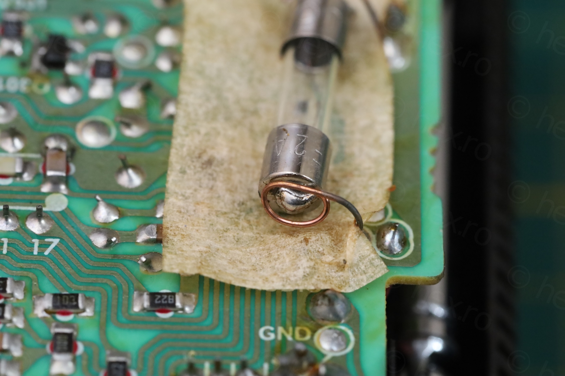
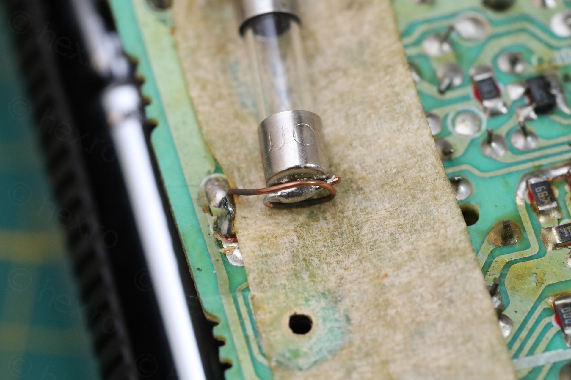
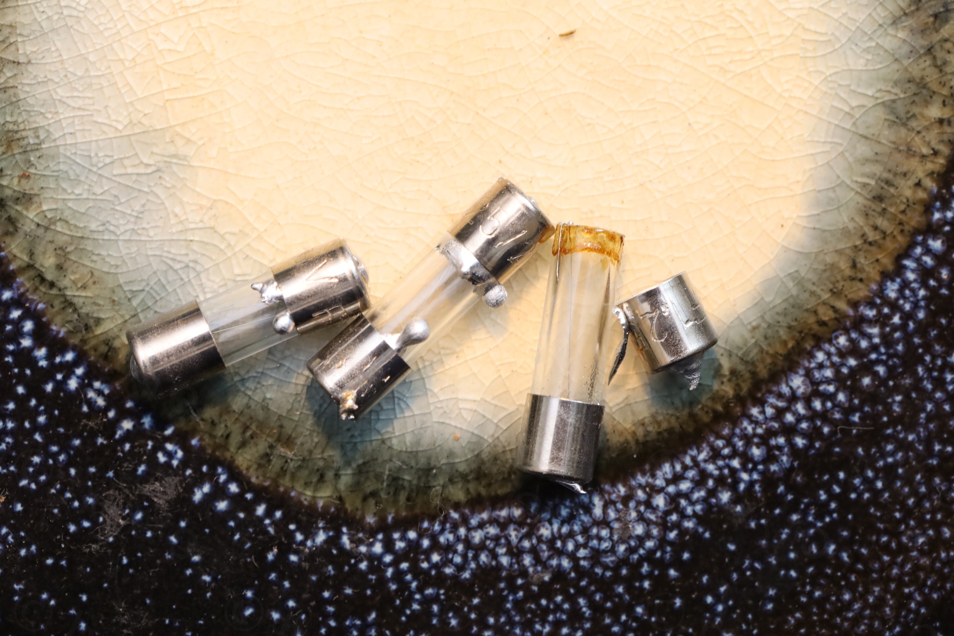
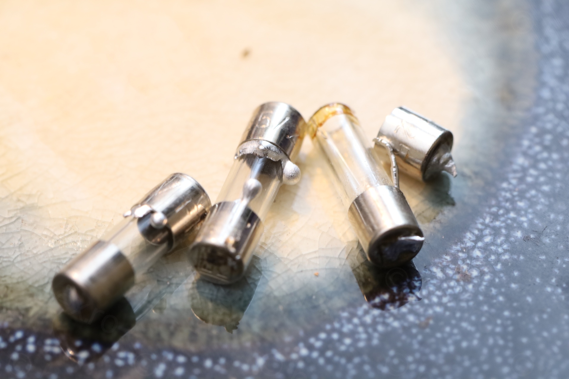
Soldering a Glass Fuse
One of the last remaining things was installing a new fuse. The one I took out was a fast, 2A fuse, but the schematics calls for a 1.25A fuse. I didn’t know if it should be a slow or a fast fuse ? I am not experienced enough to decide on what type would be more suitable. But the schematic says that expected current draw is around 0.62A. It felt weird to have a slow fuse, it’s not like there will be huge surges of current (unless something dramatic goes on). I figured, if something dramatic will be going on, better to have a fast fuse.
An additional challenge was to how to install it. The circuit board holes are spaced precisely at 20mm, but all 20mm fuse holders seem to have the pins at 22.5mm apart. Researching some videos showing the insides of Sony FD-40 TVs showed that the model did not have a holder, the fuse was soldered directly onto the circuit board.
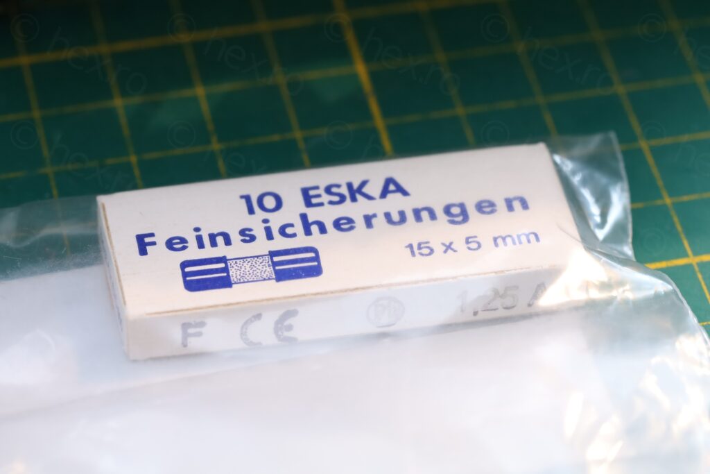
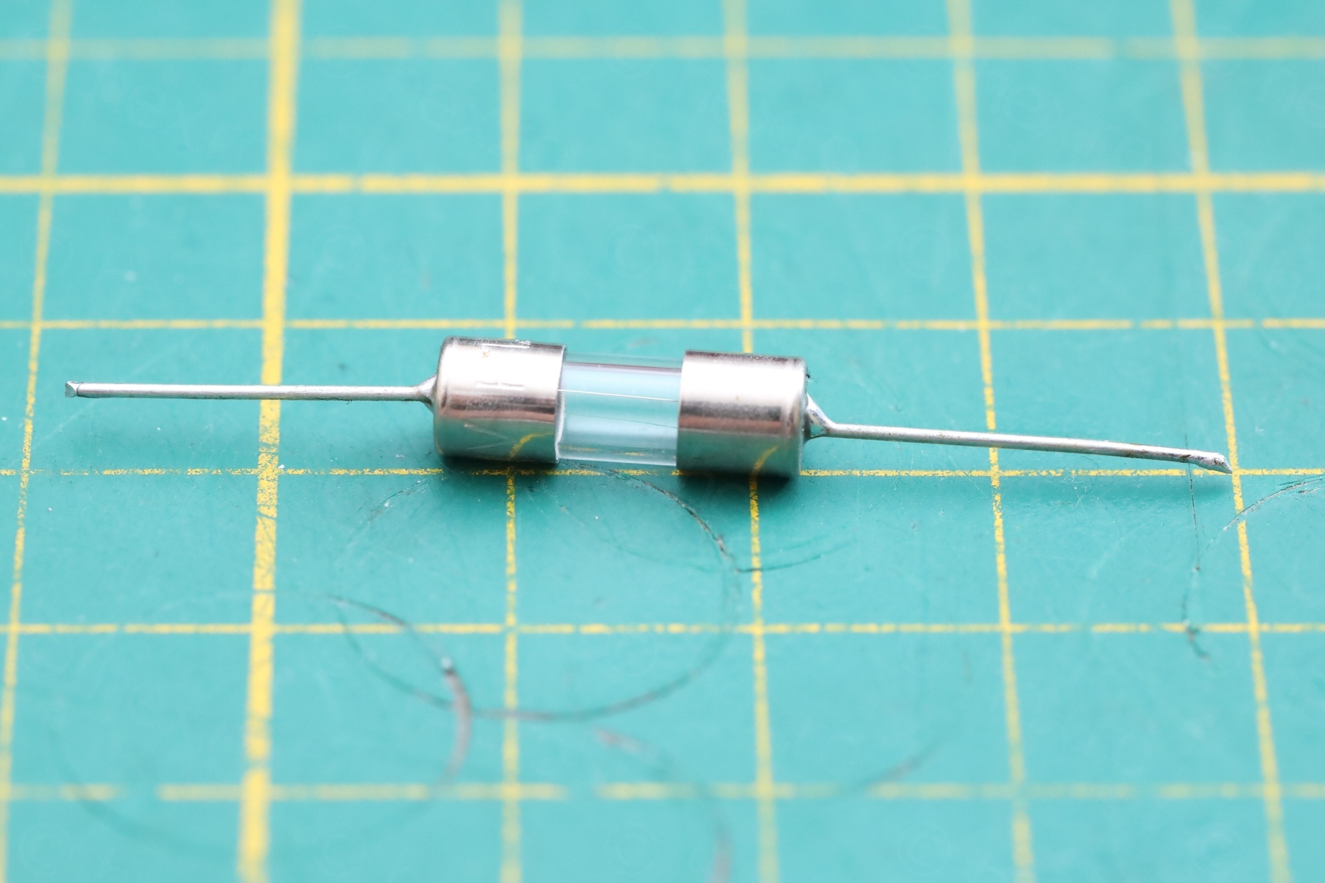
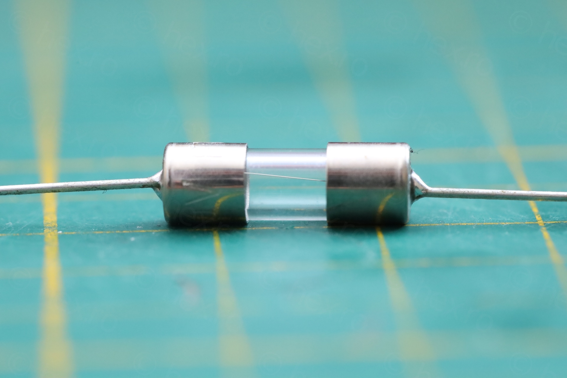
I didn’t find 1.25A pigtail fuses, so I decided to order shorter ones (15mm) and attempt to solder the leads.
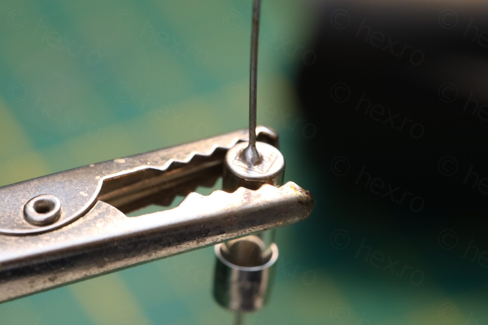
This proved very annoying. I couldn’t even get the cap hot enough to solder one lead, that a small noise was heard accompanied by solder coming out from inside the fuse! It took 3 attempts before I realized I have a problem. First, I didn’t even notice some solder was ‘ejected’ from inside the fuse, on the glass. Second, I spotted solder while trying to solder – it was confusing, where did it come from, it could not have been the one I was putting. The 3rd attempt, the glass body just de-glued itself from the cap. It was time to stop and think.
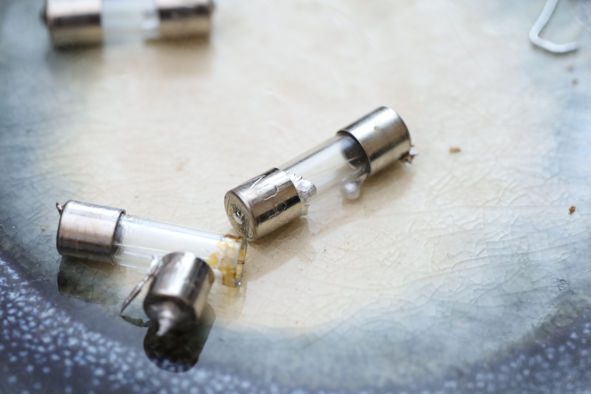
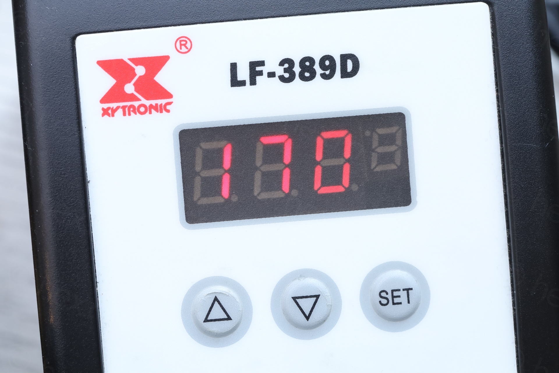
I was using 250C with normal solder – and apparently this was too much, as, the fuses themselves also seem to have some solder inside (probably the wire is soldered too, inside the caps). The last attempt was successful, since I decided to try using low melt solder with the iron set to 170C:
Most likely I will never use the TV on batteries, it is aesthetically pleasing to have the fuse installed and the TV complete.
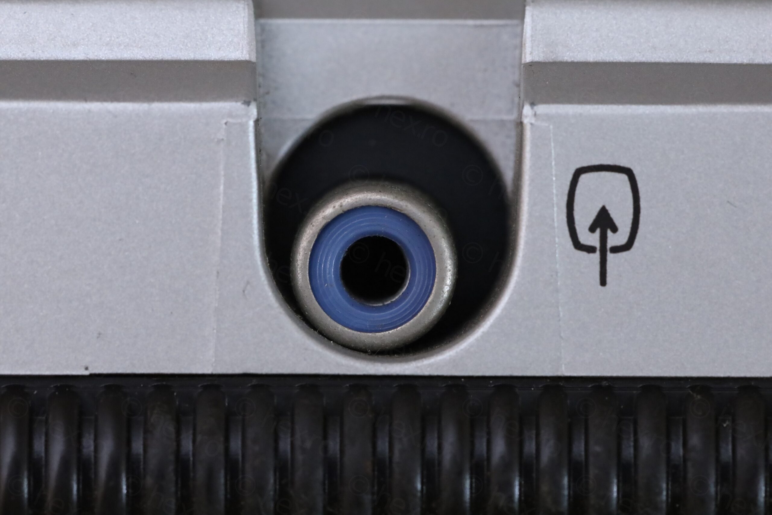
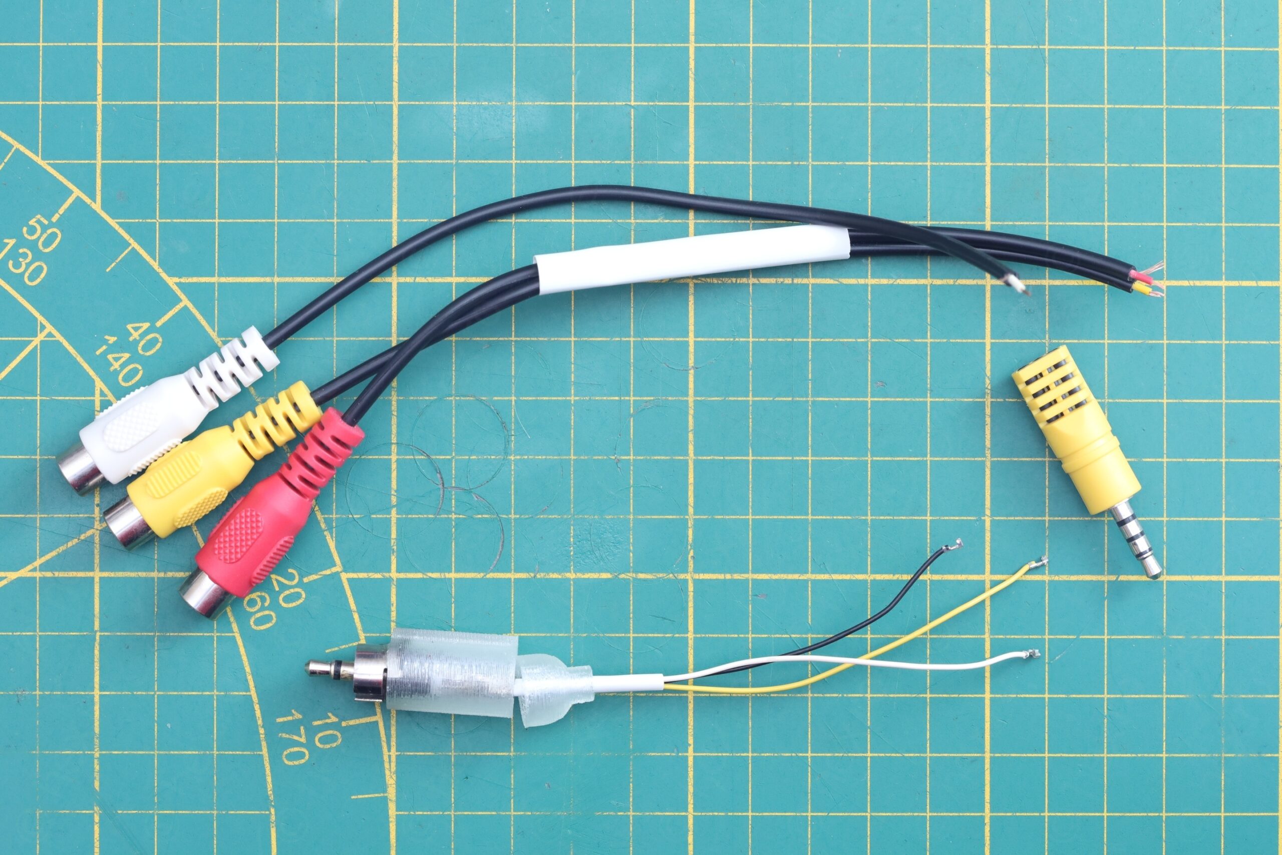
Custom RF Adapter for Sony FD-40
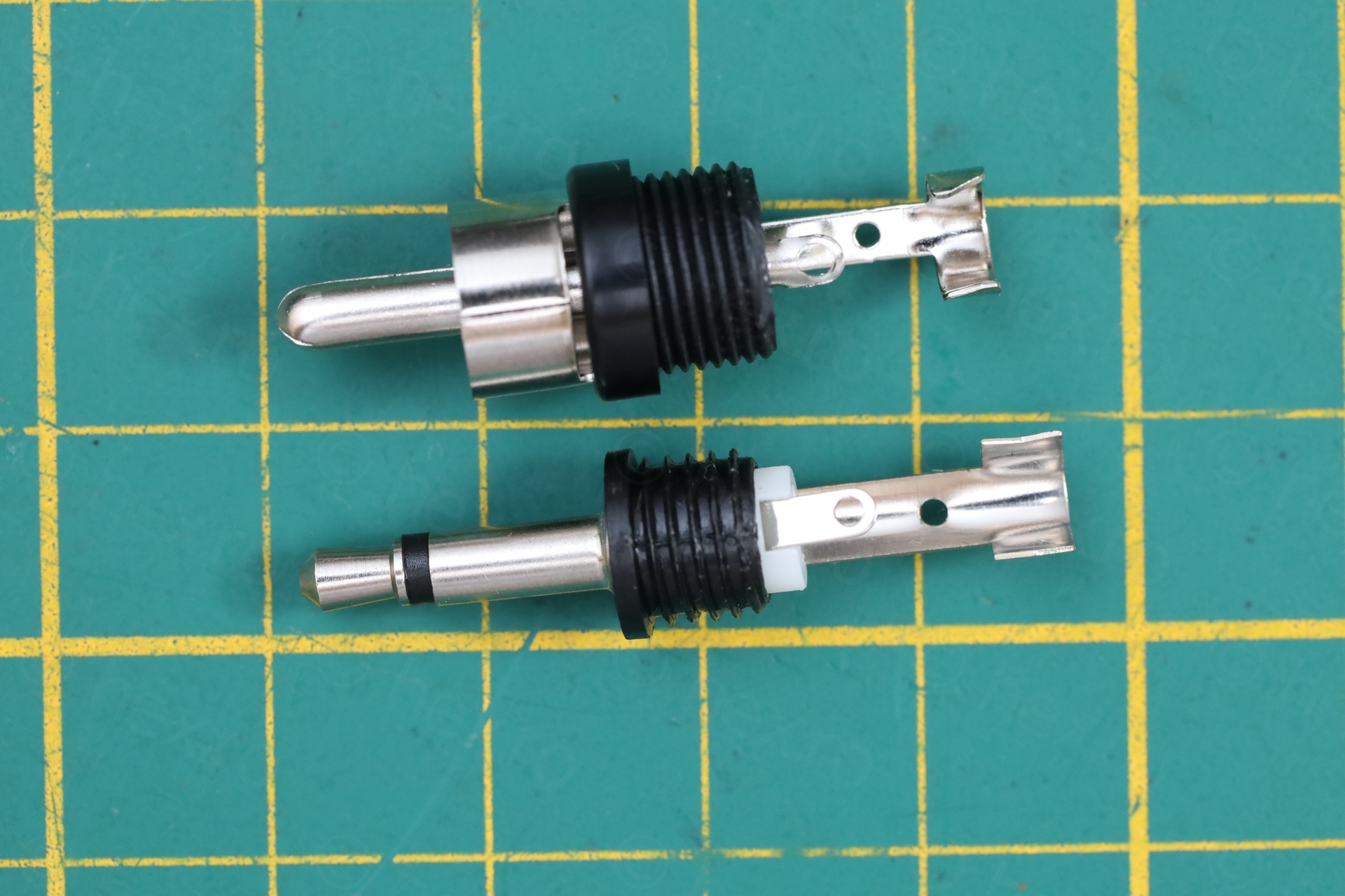
Without an External Antenna input, I needed a way to bring signal to the TV. I came up with an DIY adapter made from an old-school 3.5 mono jack and paired with the ground connector from an RCA jack. The TV uses what it looks like an RCA jack, but it is not.
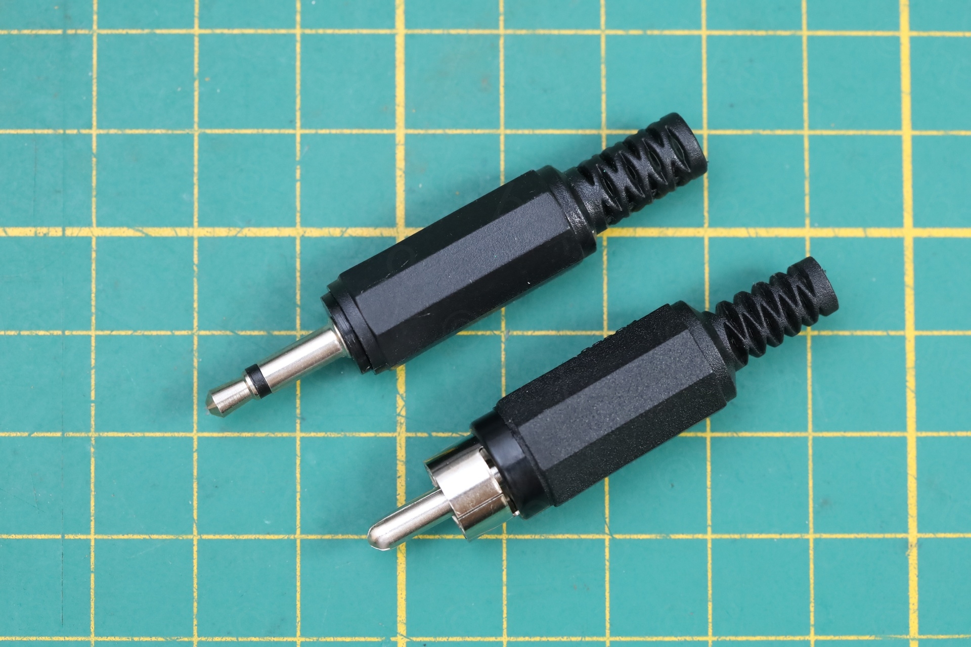
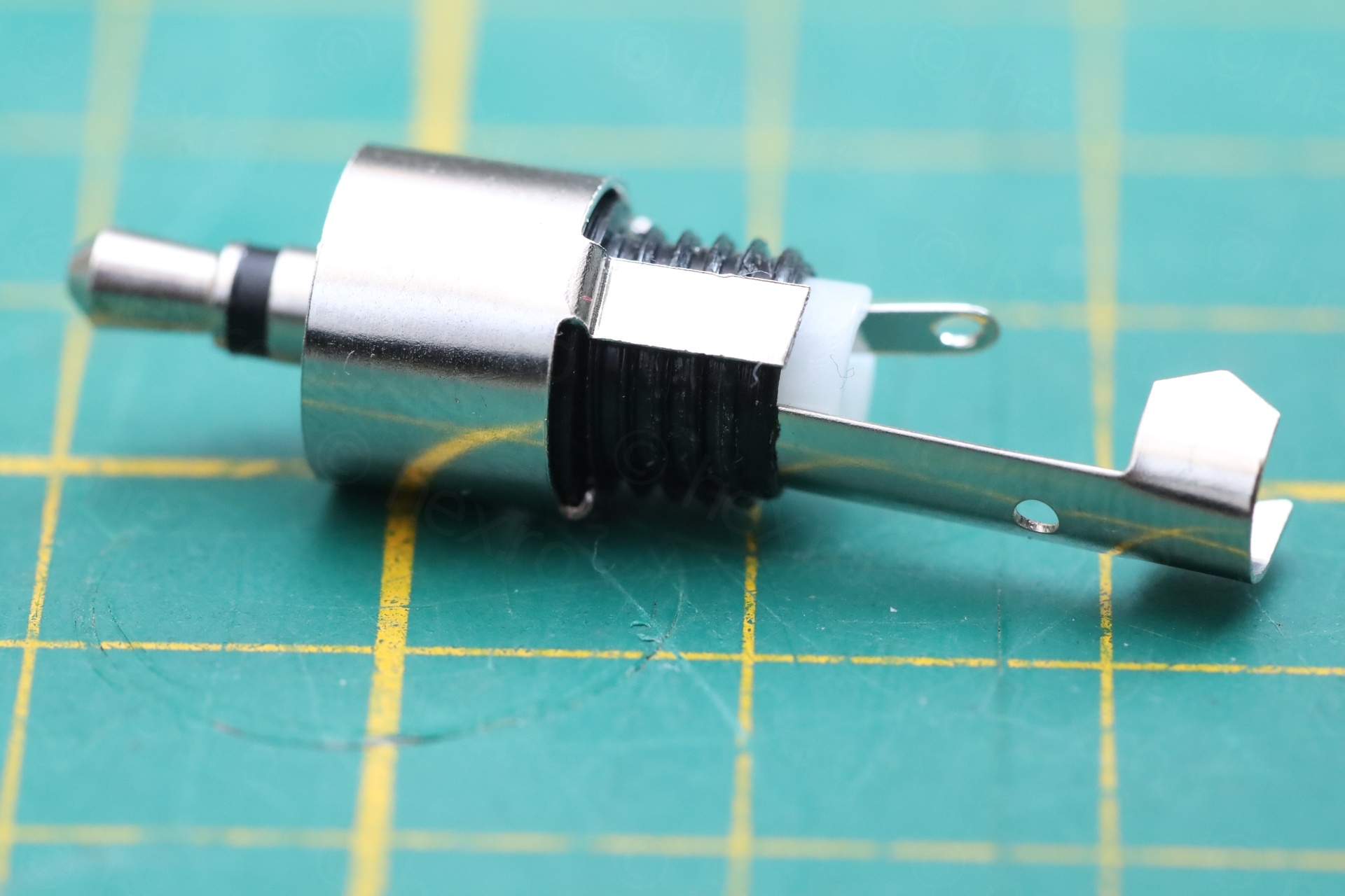
I had two failed attempts before I reached the working setup, but it boils down to:
- The mono jack has to go all the way into the TV socket. Only then the TV switches from RF input to Video IN input.
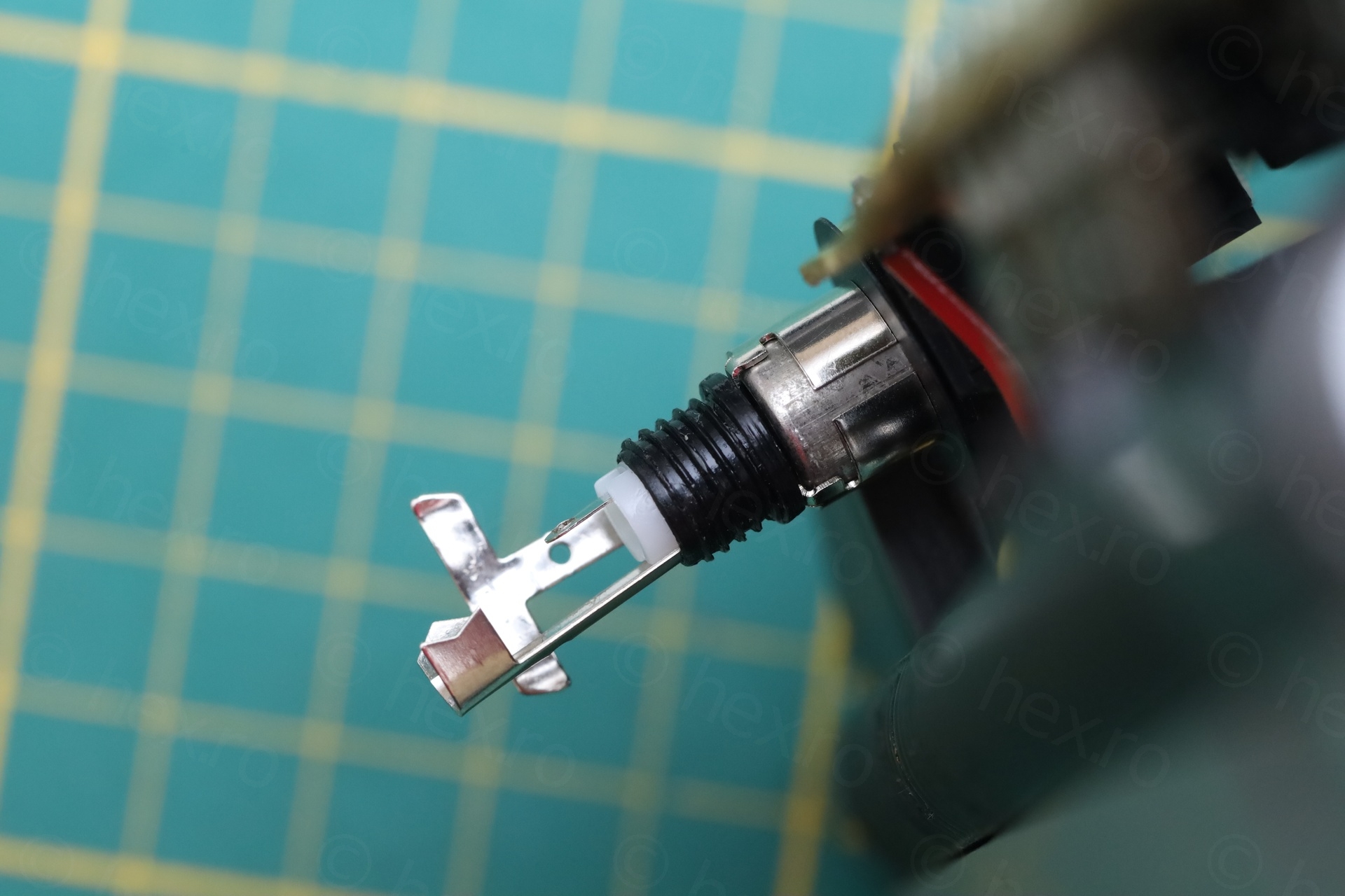
- The ground ring of the RCA jack is too tight to get around the TV socket, so I had to pull on it to make it wider. There should not be much force required to insert the Video IN adapter.
- The ground ring must not make electrical connection with any metal part of the 3.5mm jack
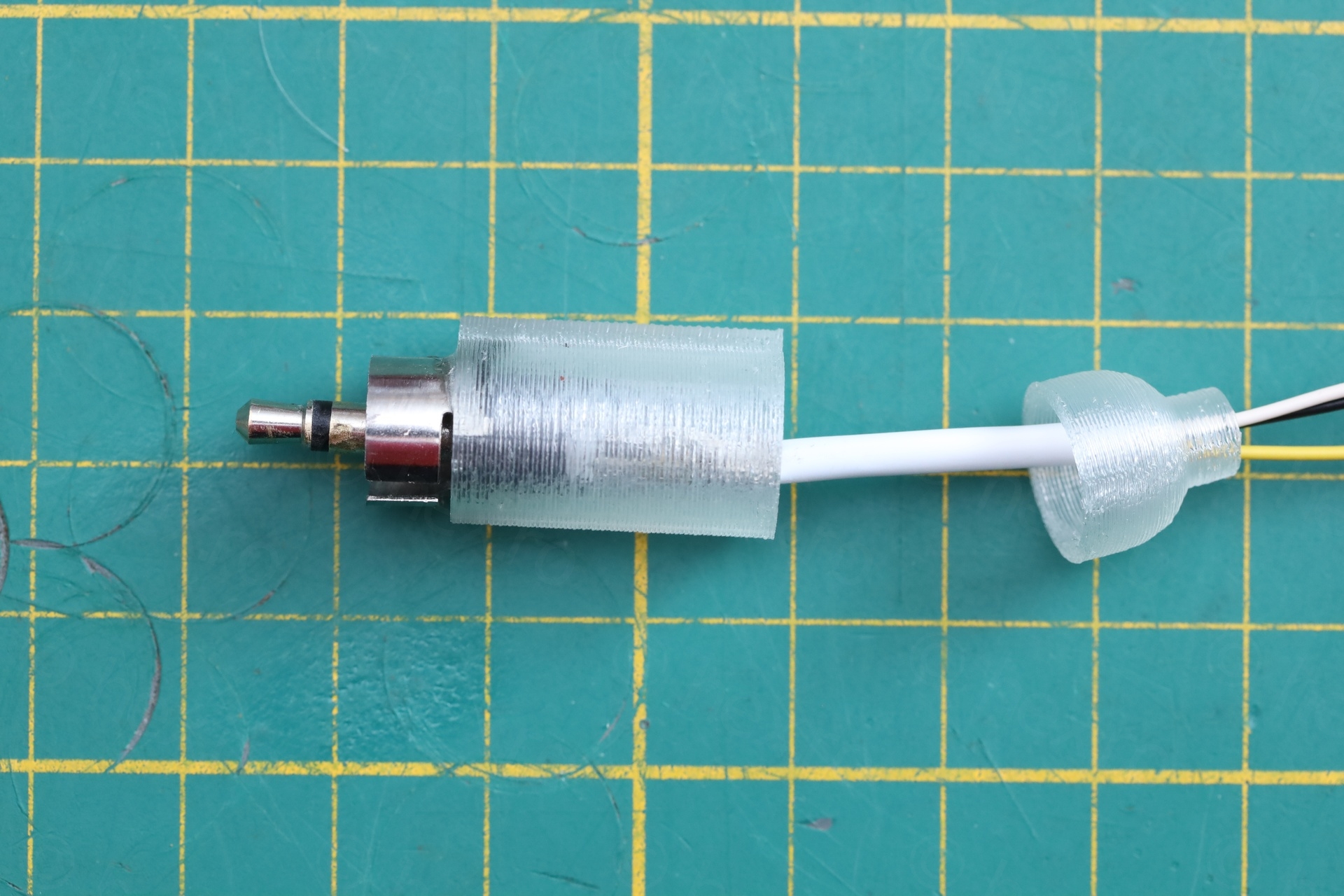
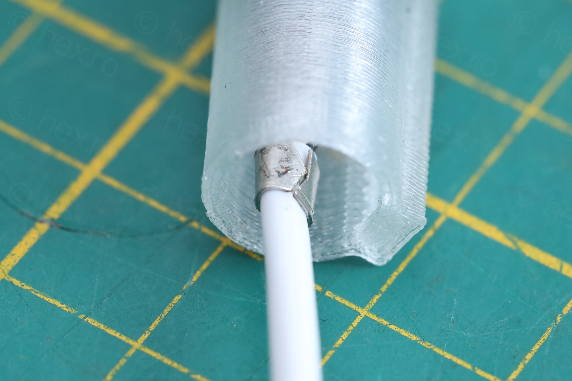
- Centering and gluing the RCA ring around 3.5mm jack, was done with the help of a 3D printed part that I designed in FreeCAD. This allowed me to glue both the RCA ground ring as well as the jack and keep them securely in place.
The tip of the 3.5mm jack will be the Audio input, and the sleeve will be the Video IN signal. I payed attention that the ground (the RCA ground ring) is soldered to both the RCA inputs (Video IN and Audio).
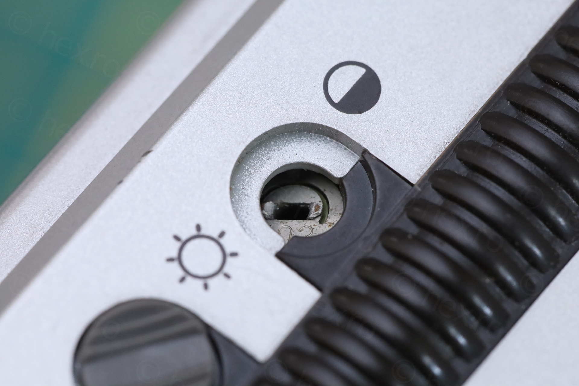
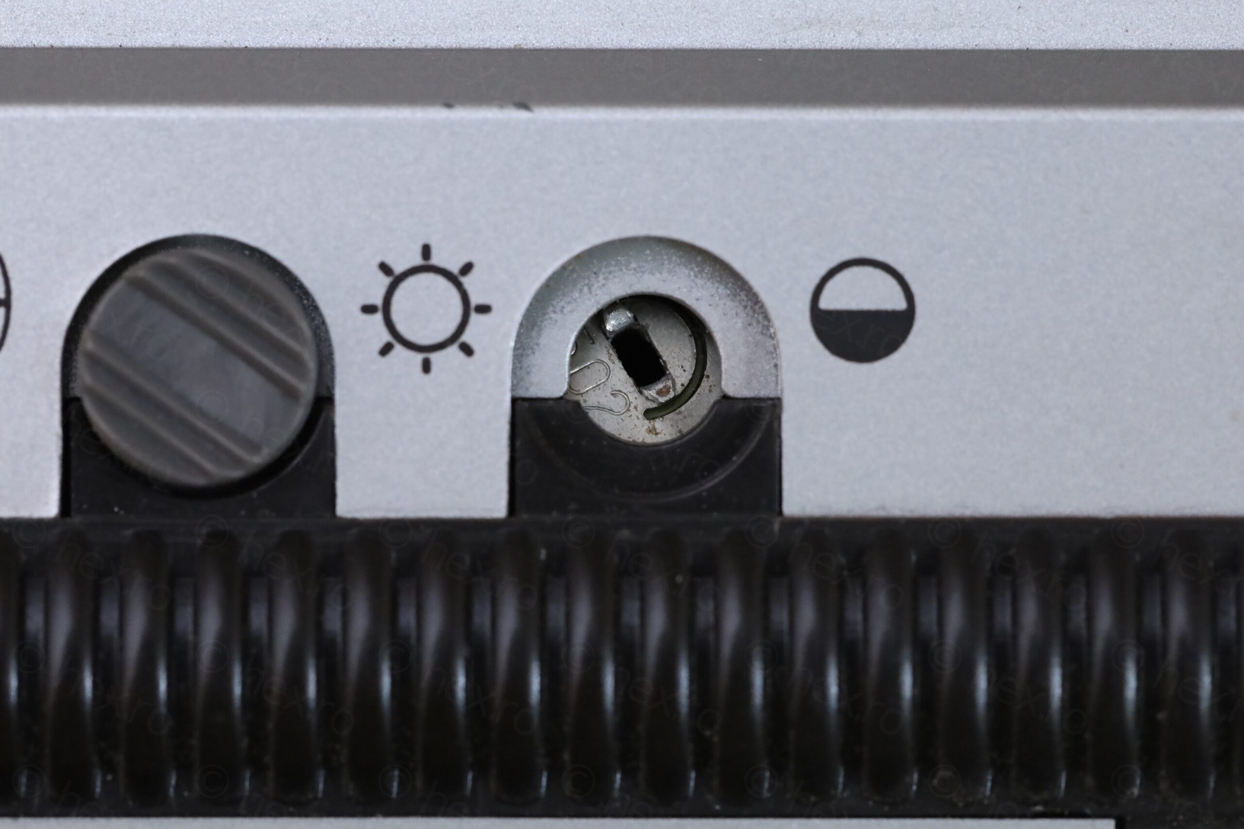
3D Printed Adjustment Knobs
The TV came only with the Brightness adjustment knob – and that one was also almost to the breaking point:
I looked at the 3D printer. While I would be able to re-design the knob in FreeCAD, it would not last in the TV. Few reasons: the potentiometers are hard to turn and the and sharp. And printing with stronger plastics, at such a tiny volume, there won’t be enough of them to distribute the load – the 3D part would be very weak.
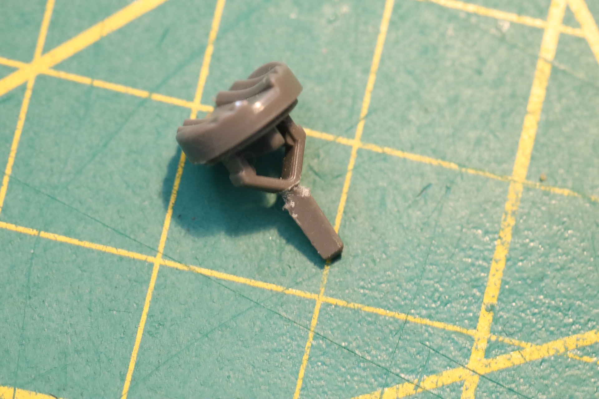
Thus, after a lot wondering what to do, I came up with this (what I believe to be an acceptable) solution:
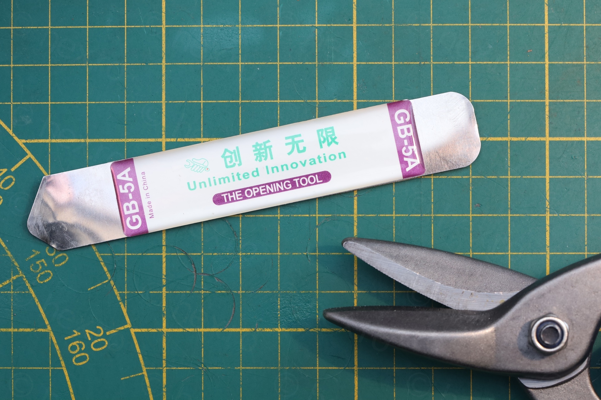
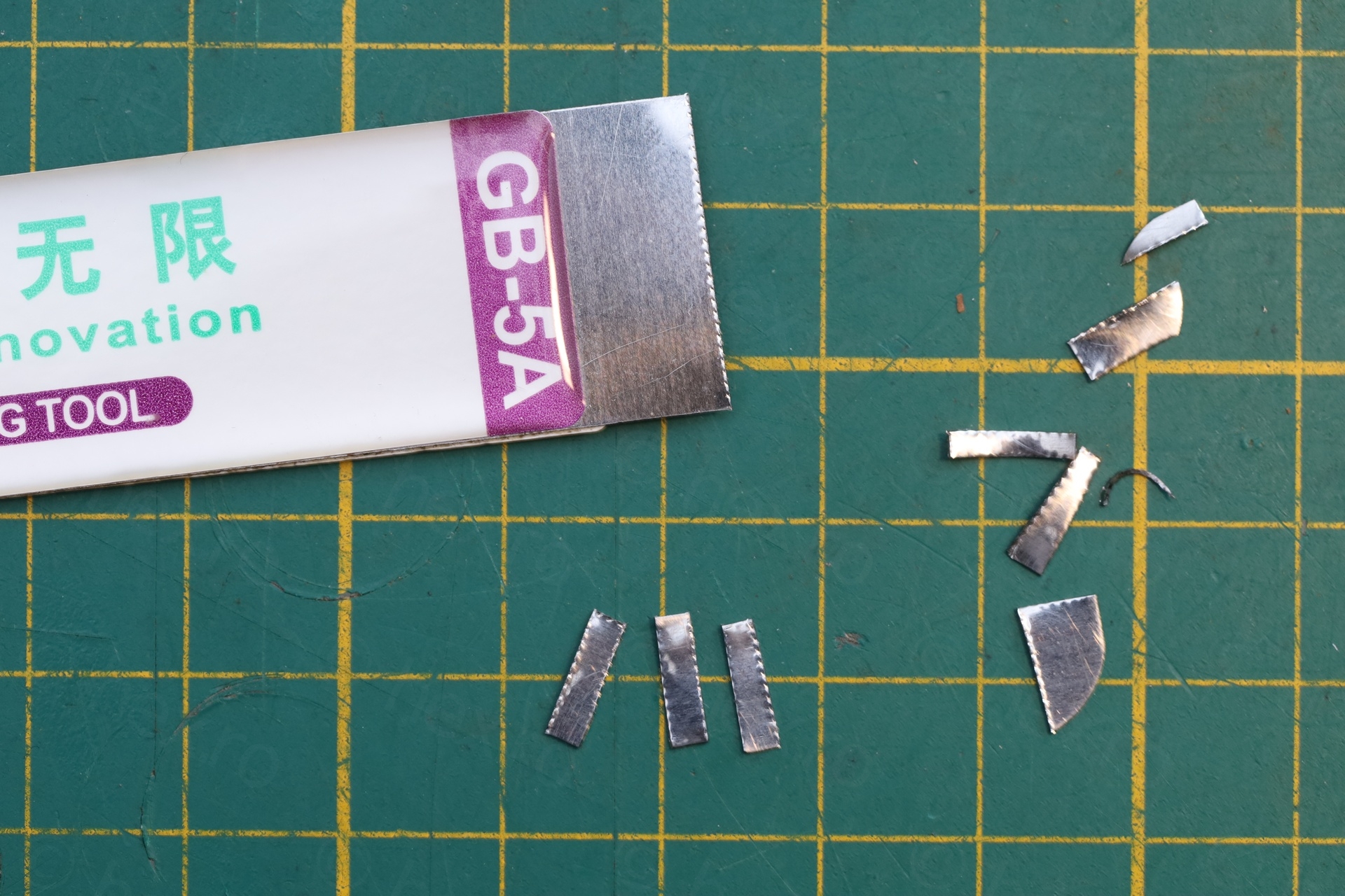
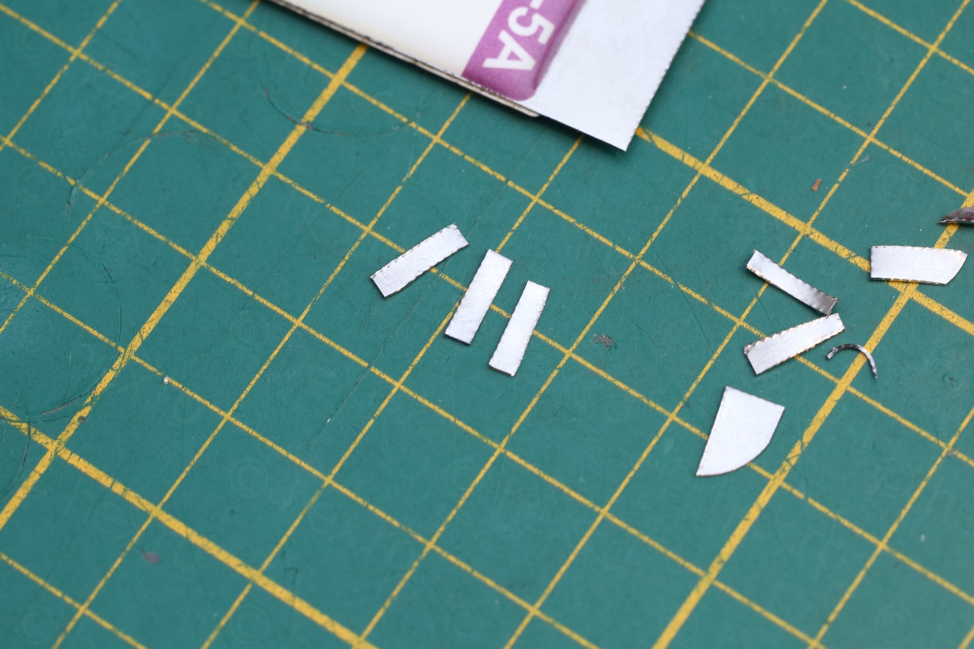
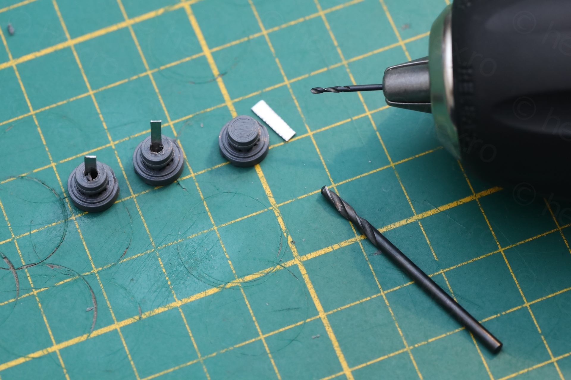
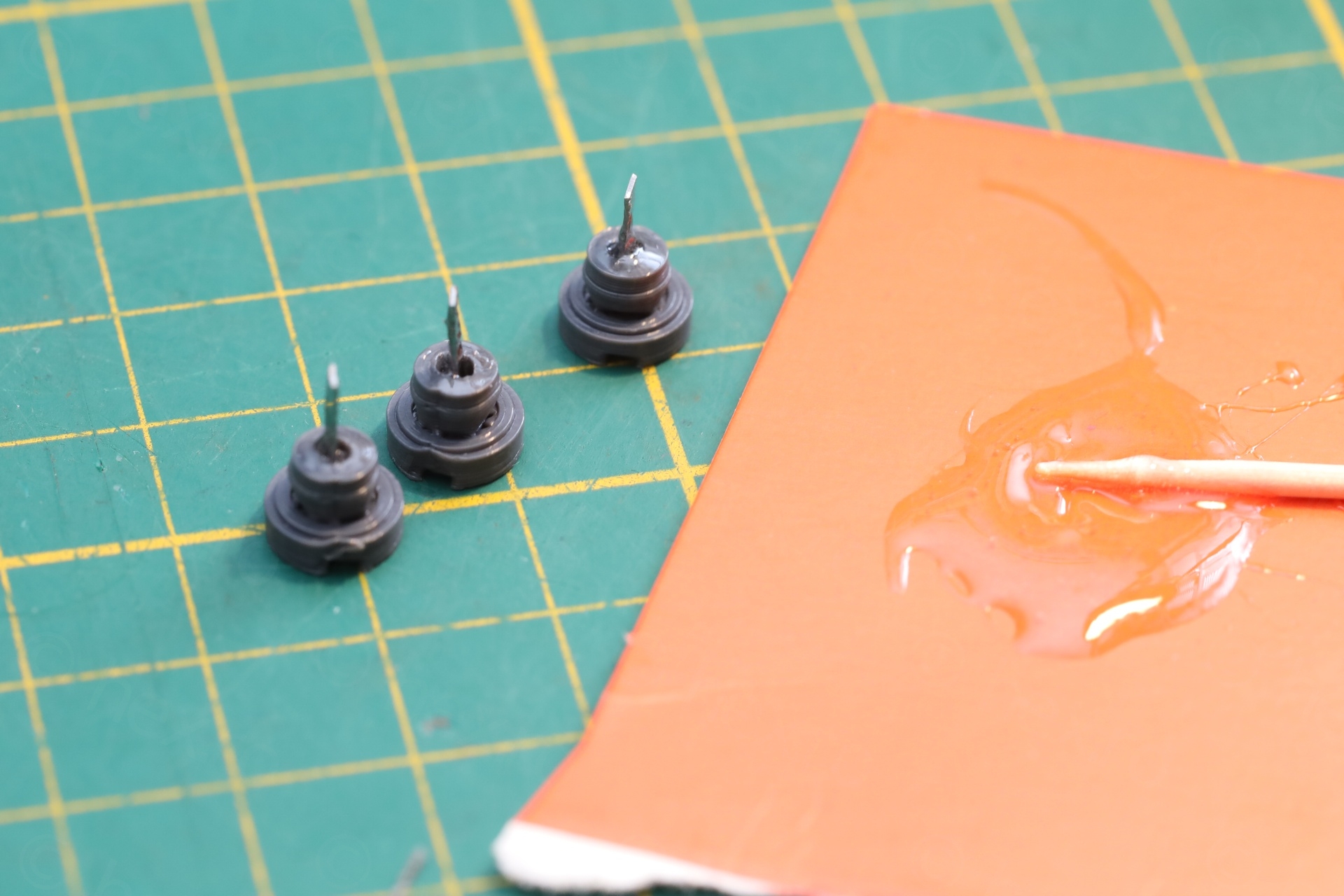
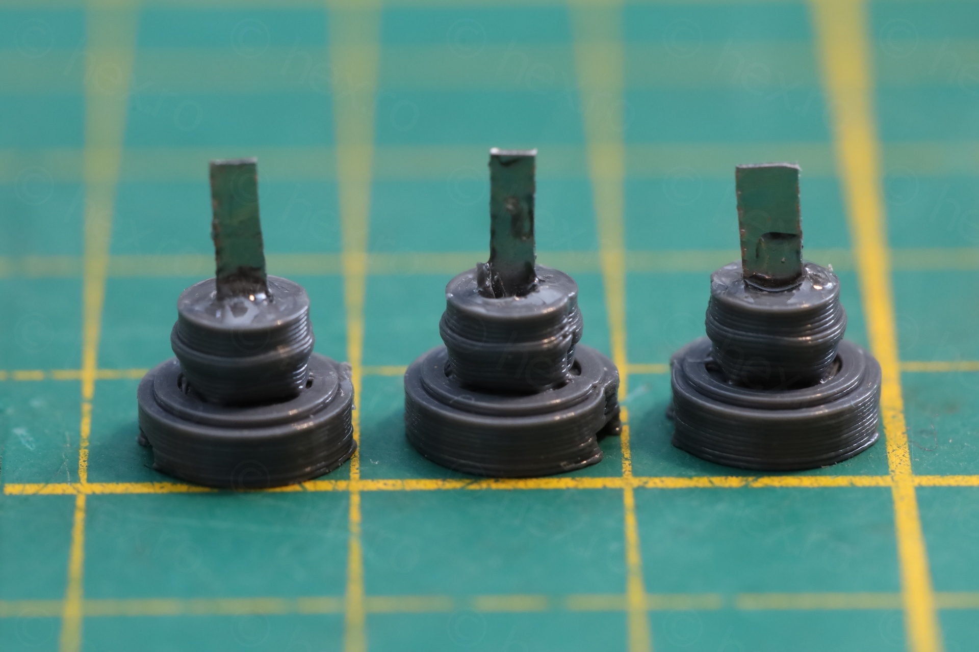
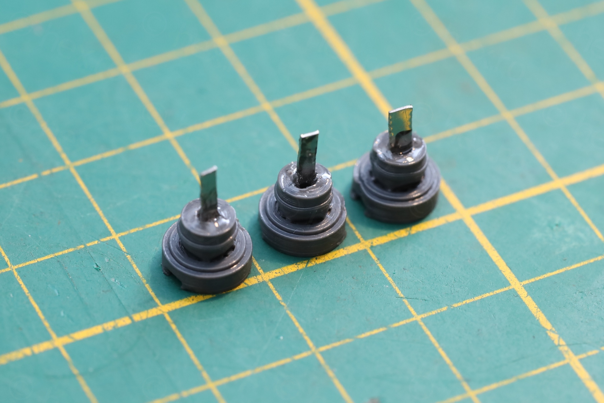
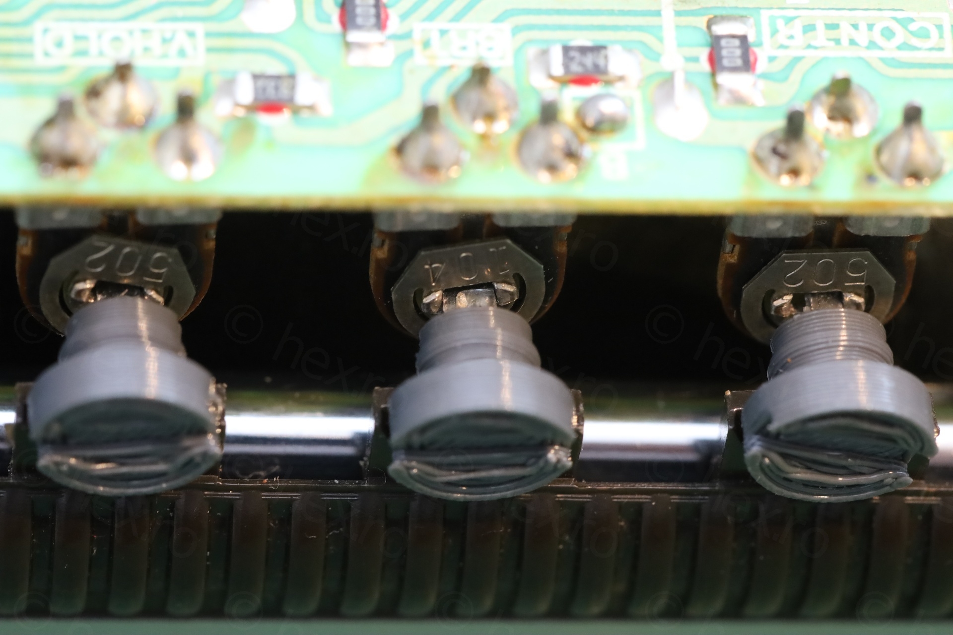
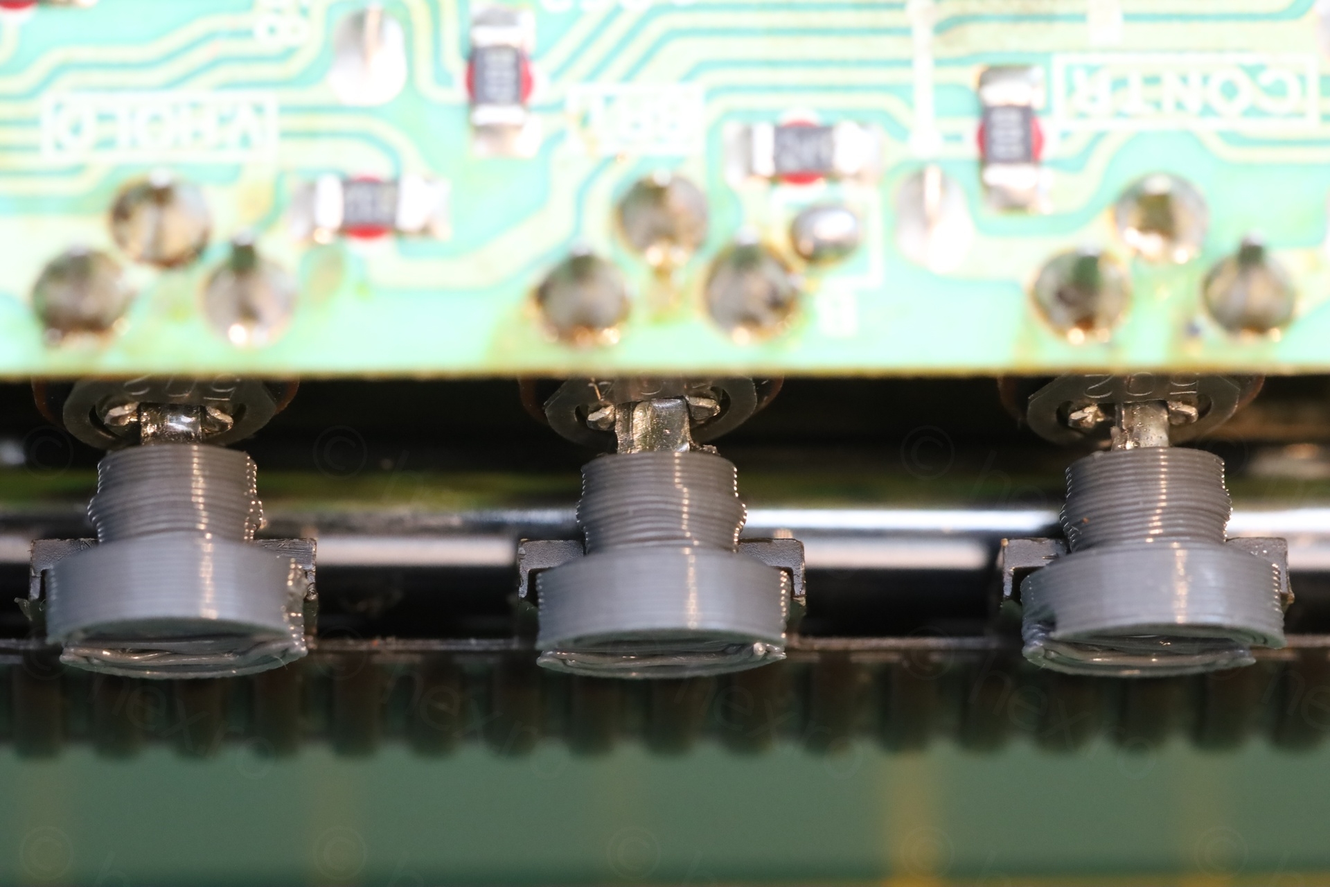
I have only 3D printed the thumb part, drilled a hole in the center and used some thin metal from a flexible pry tool as shafts. I used plenty of epoxy to make sure the metals do not dislodge and fall into the TV itself.
I think the only drawback is that the metal is too thin and the slots in the pots are too wide, meaning, there is some left-right wiggle room. But the buttons serve their purpose and when looking from afar, I can’t even tell they are custom made.
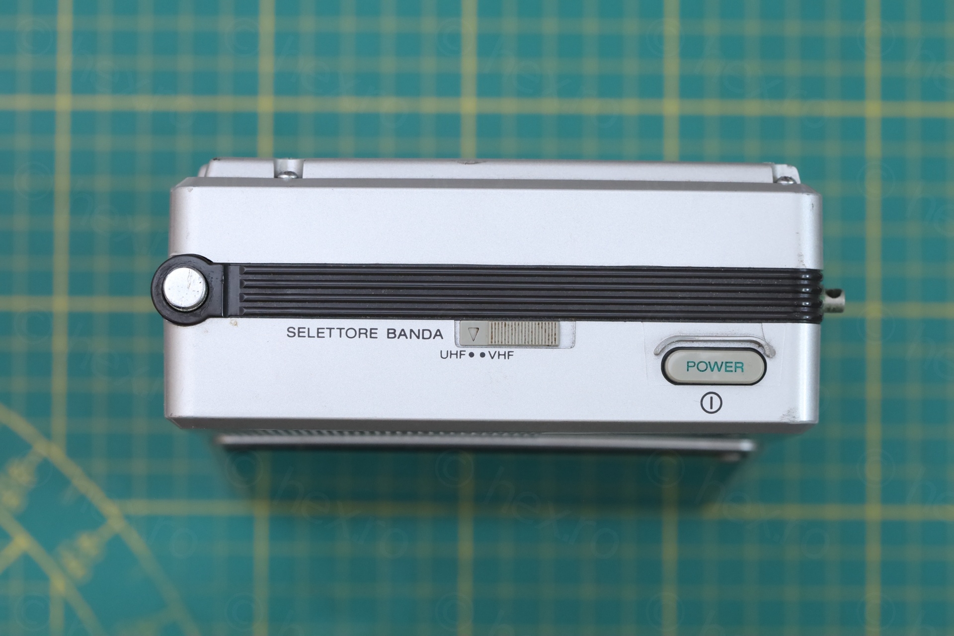
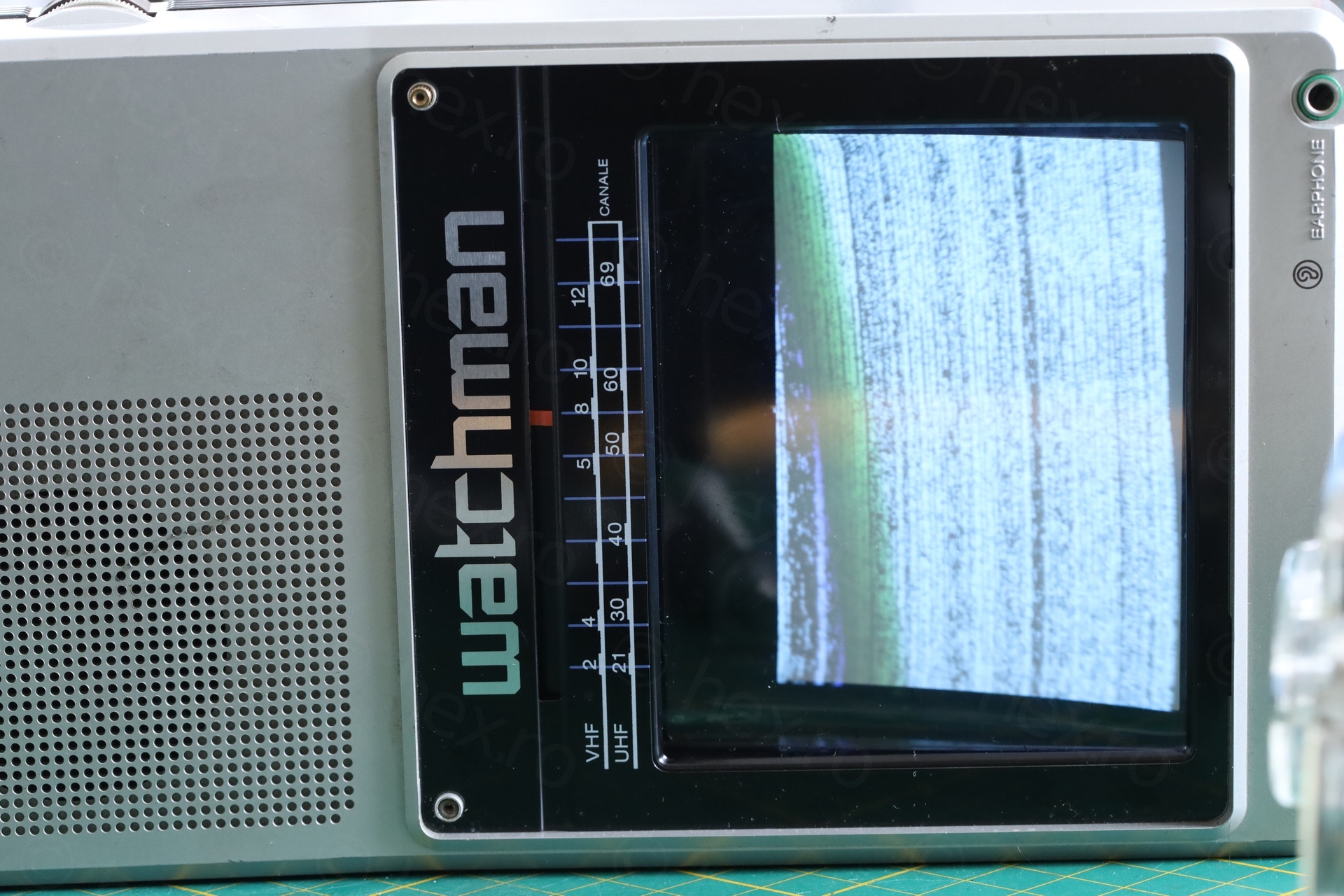
Calibration
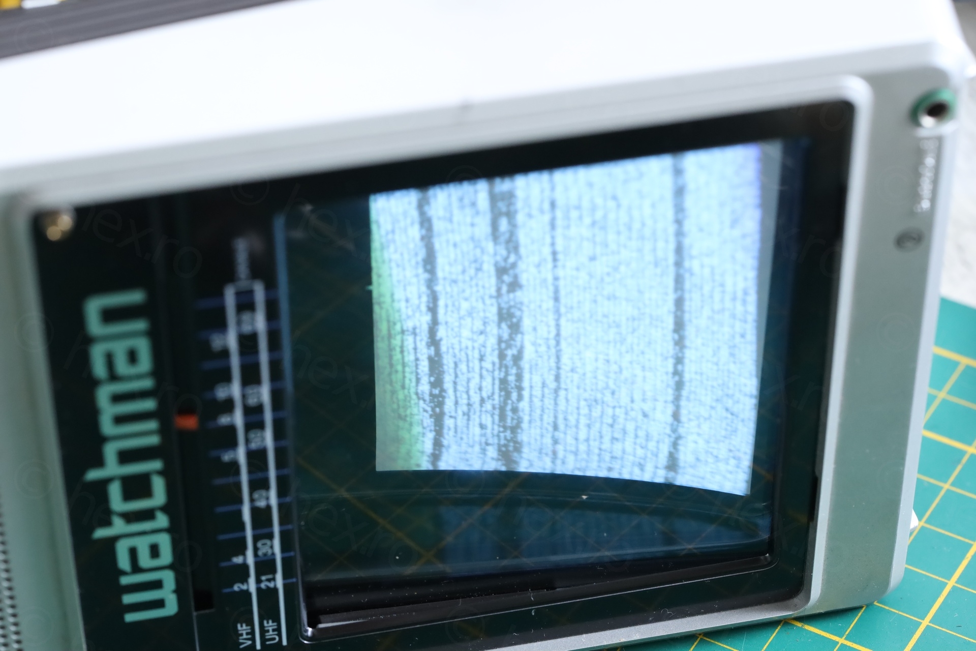
The TV has wonky image, left side is lifted and the top shows a bowing effect.
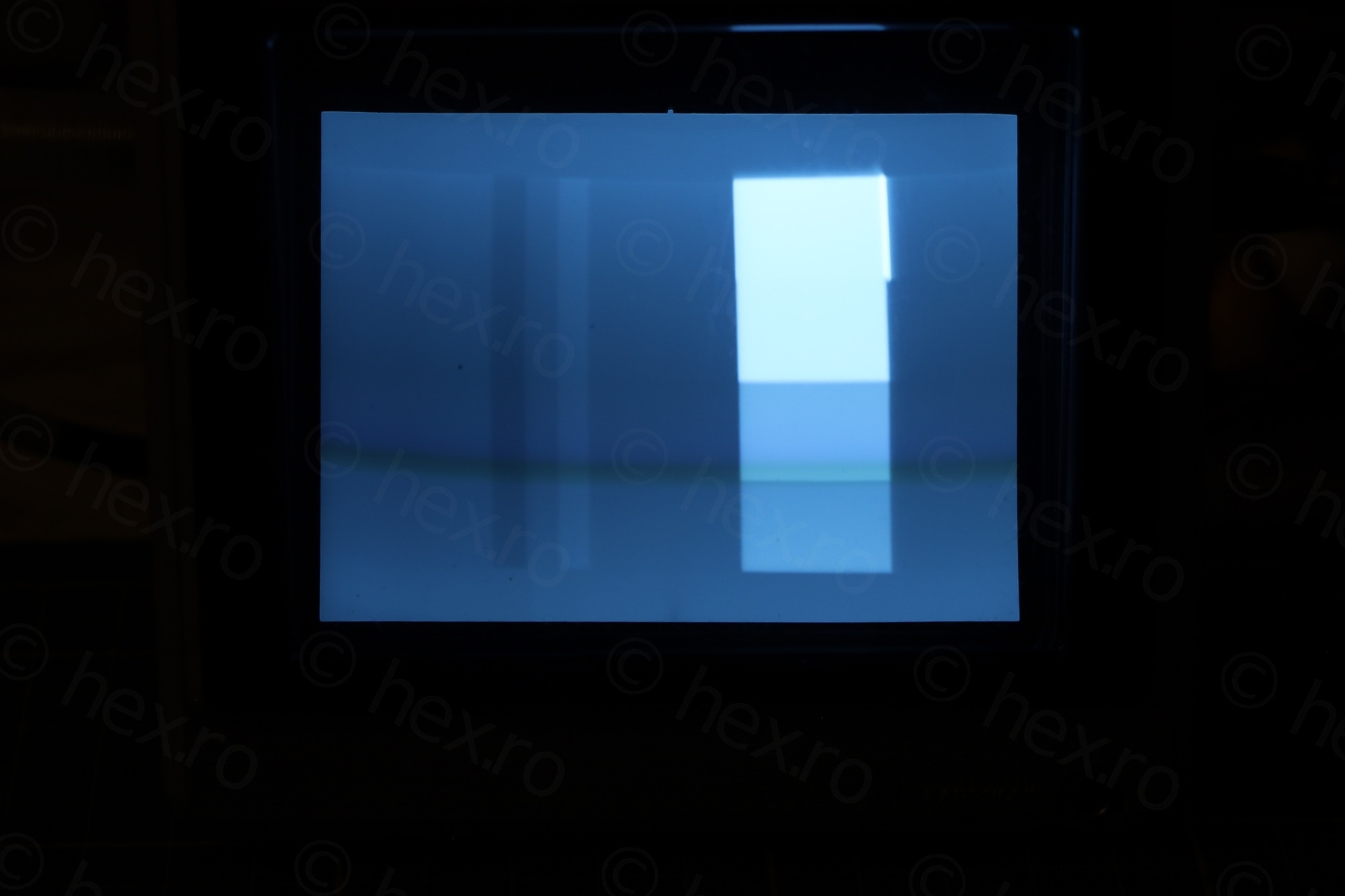
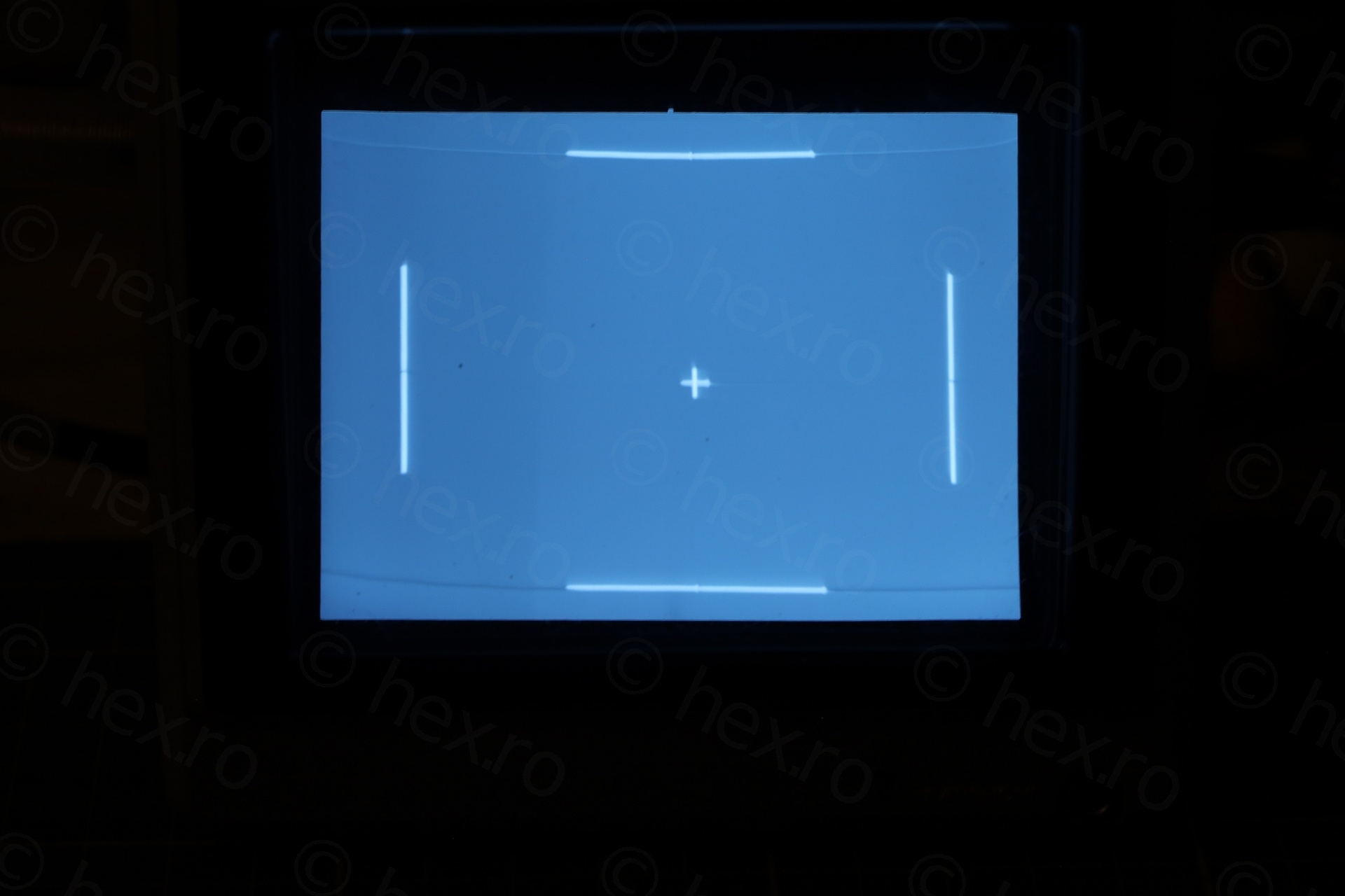
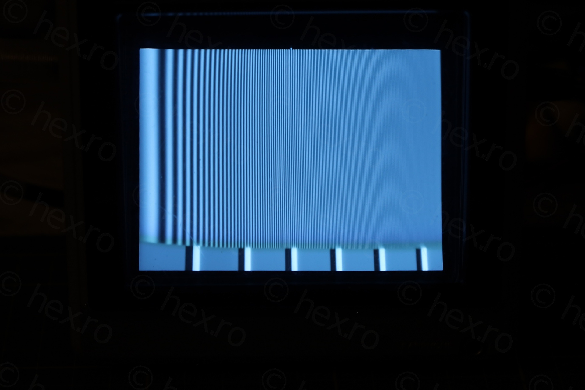
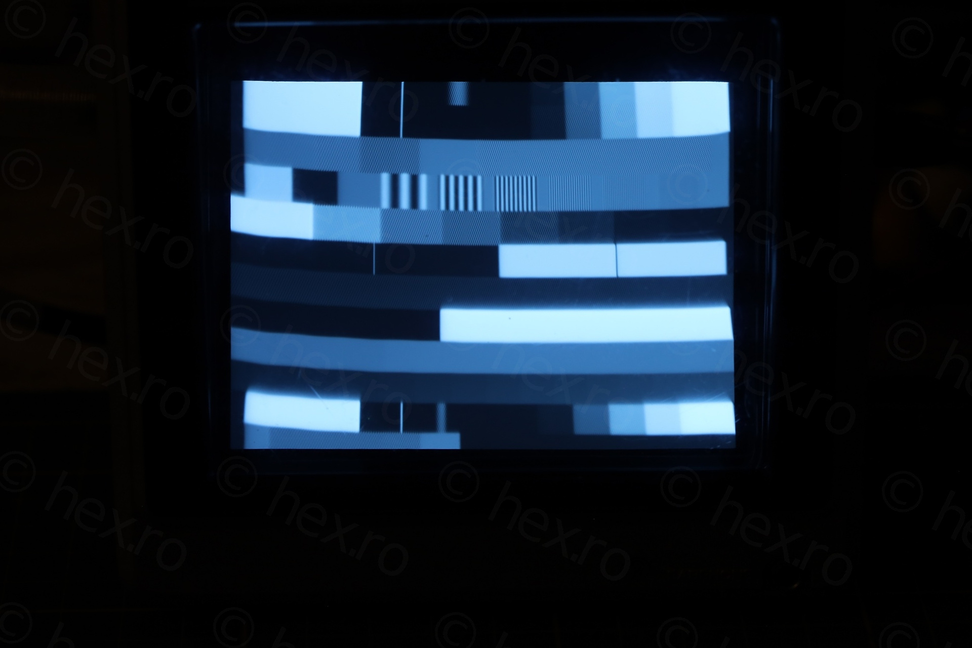
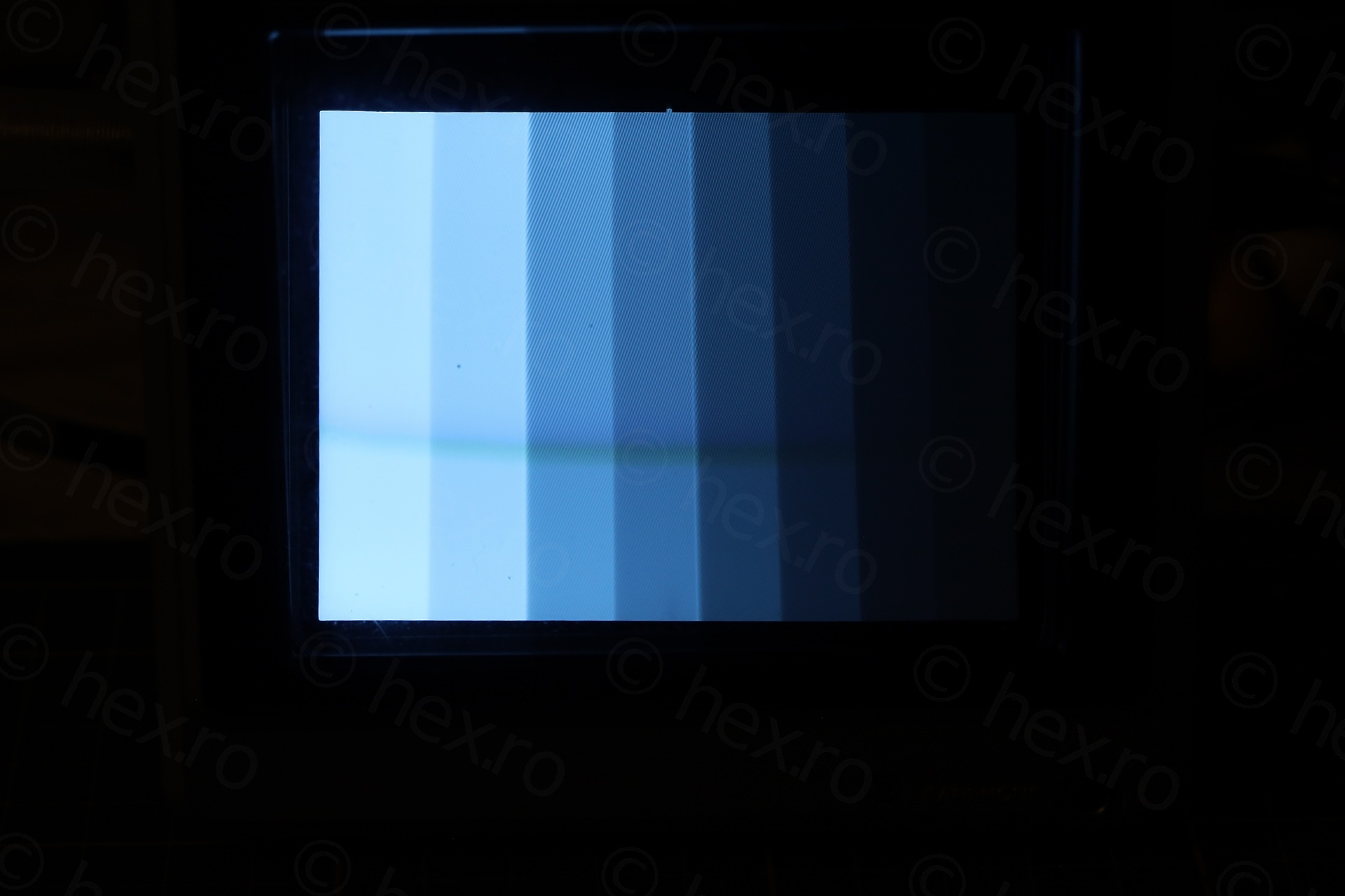
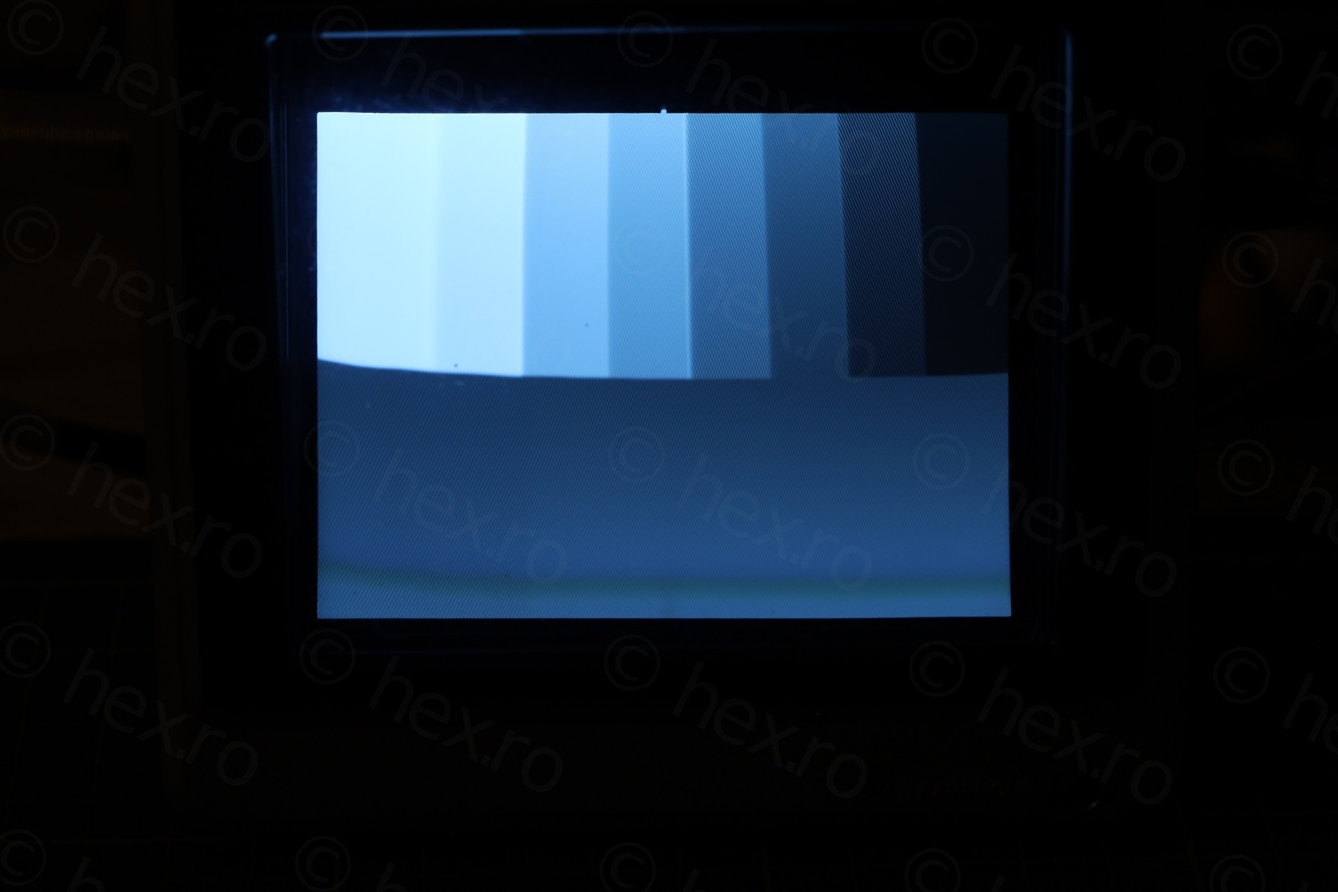
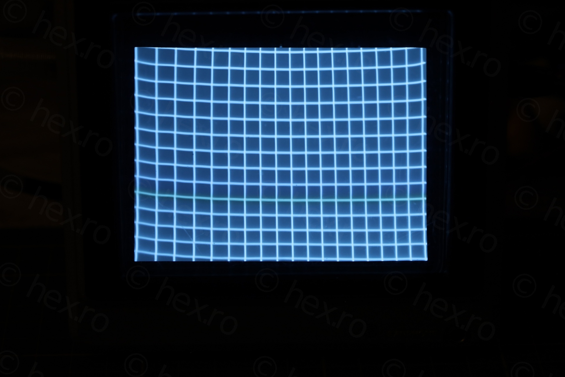
I performed all possible calibrations from the service manual. I also went through a lot of freeze-spray trying to see if other capacitor / parts may influence the image.
No luck. I do not know how to debug the problem, not enough knowledge on this. Maybe it needs a different CRT, or, maybe, when the TV was dropped, something got bent in the deflection yoke. Or, maybe, it is the nature of the TV itself. Youtube videos of the same model show similar distortion pattern.
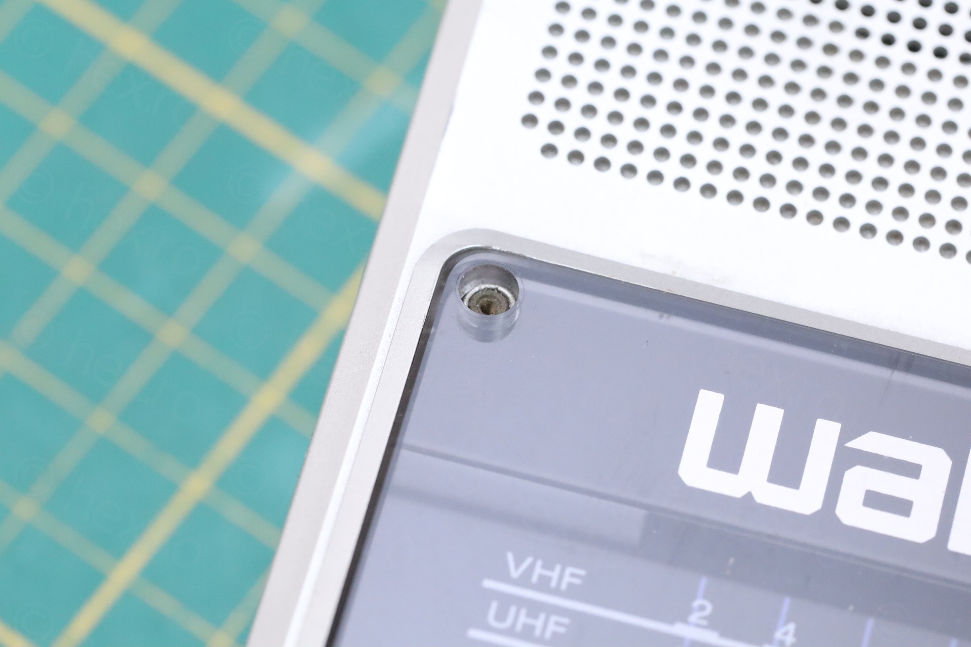
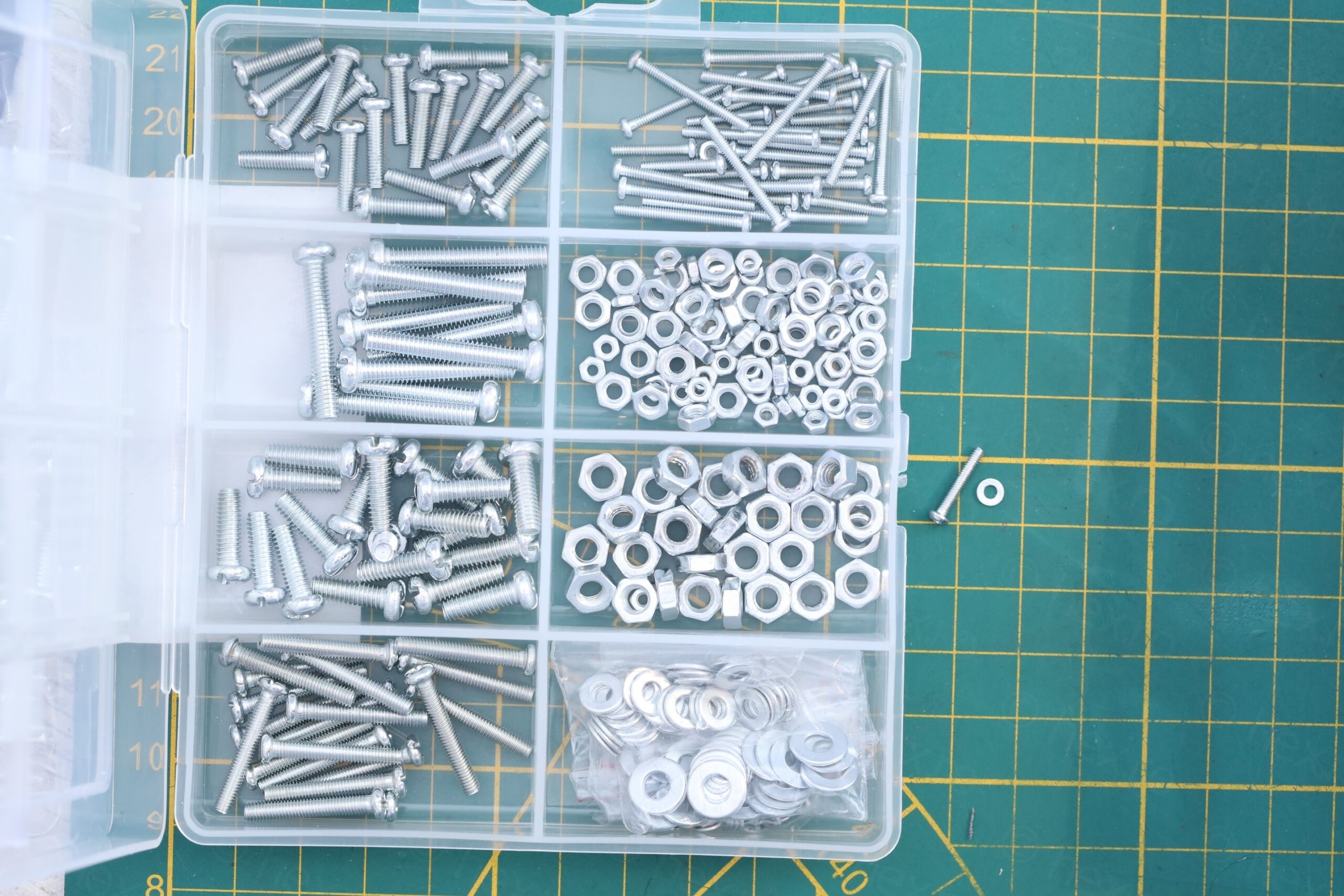
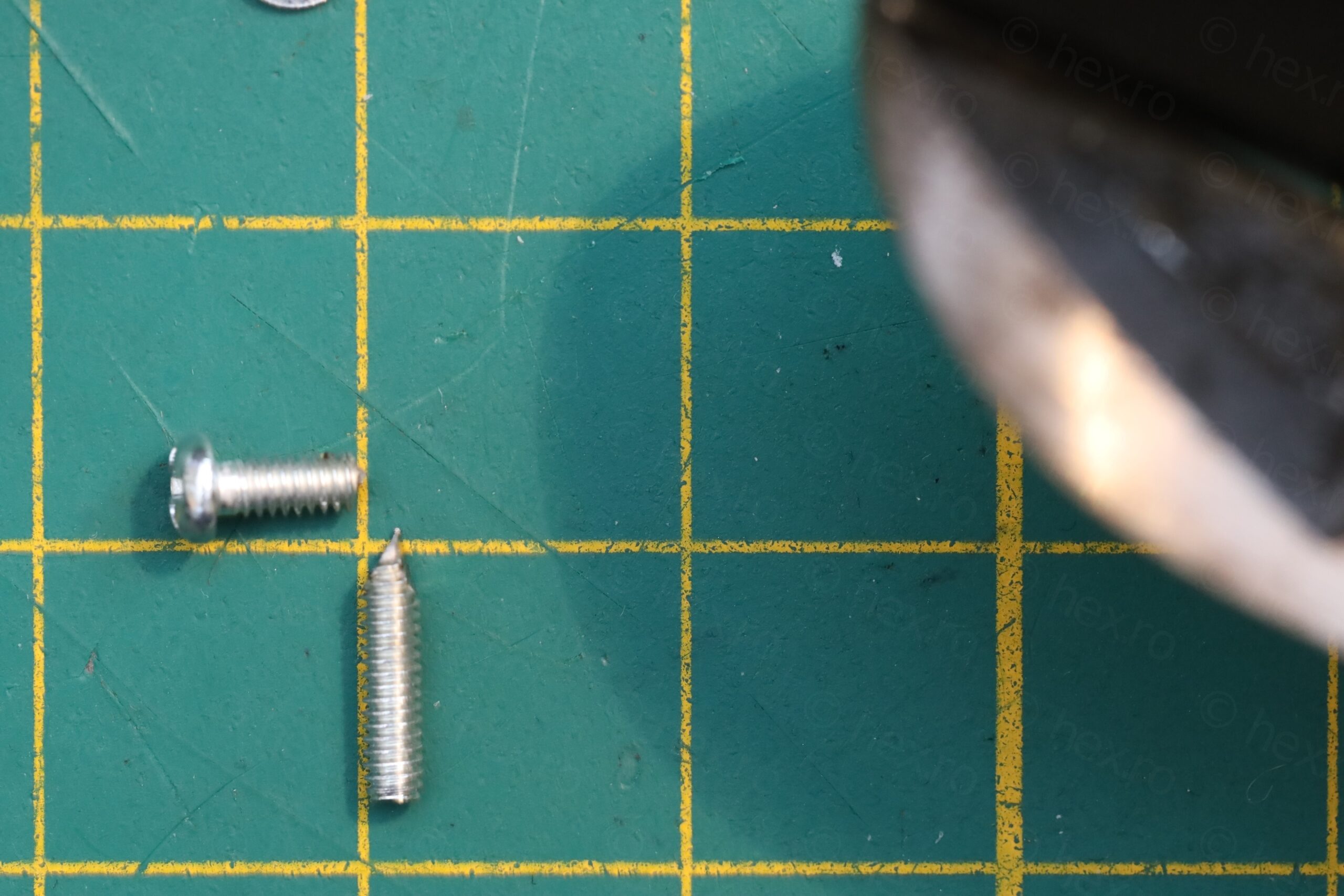
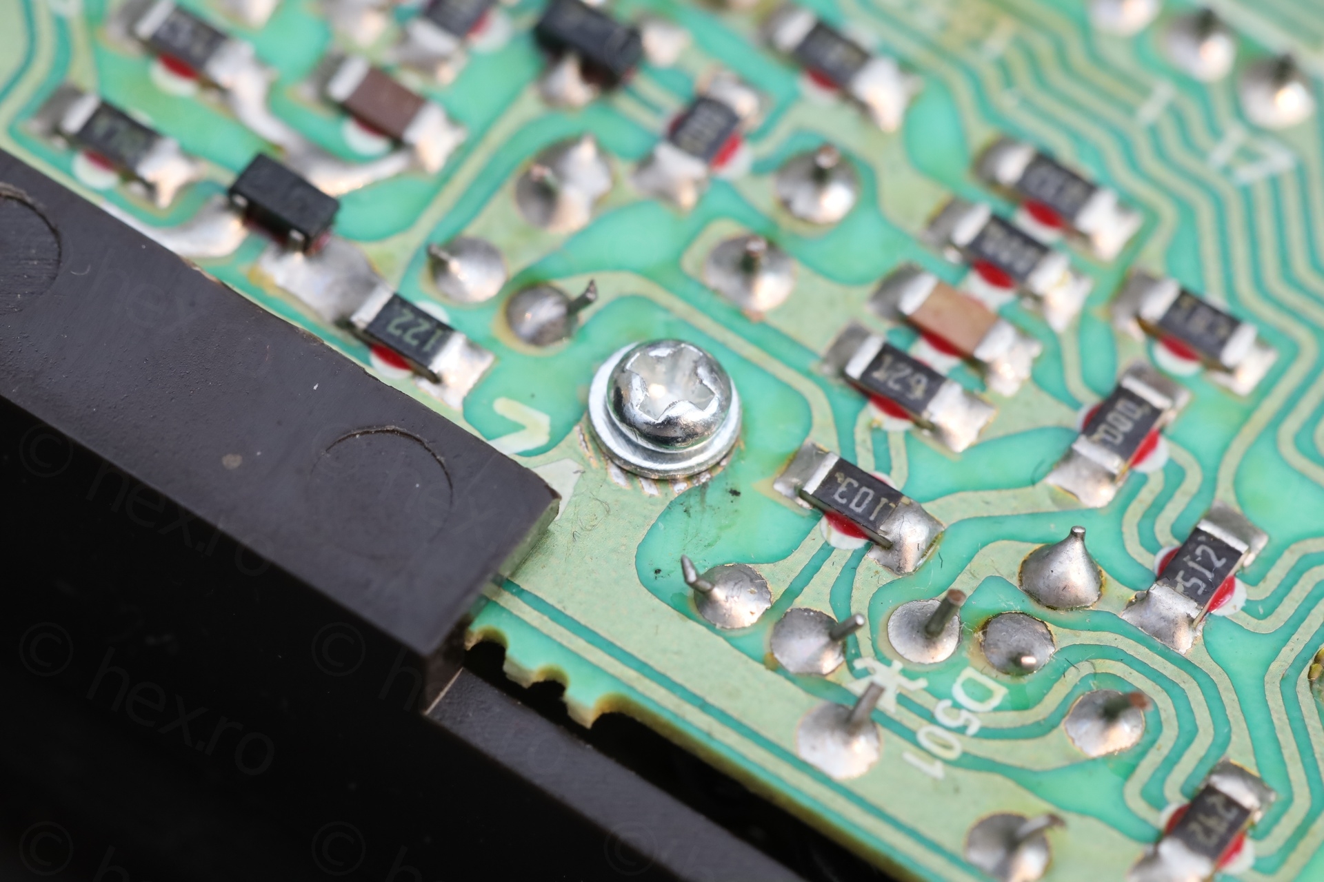
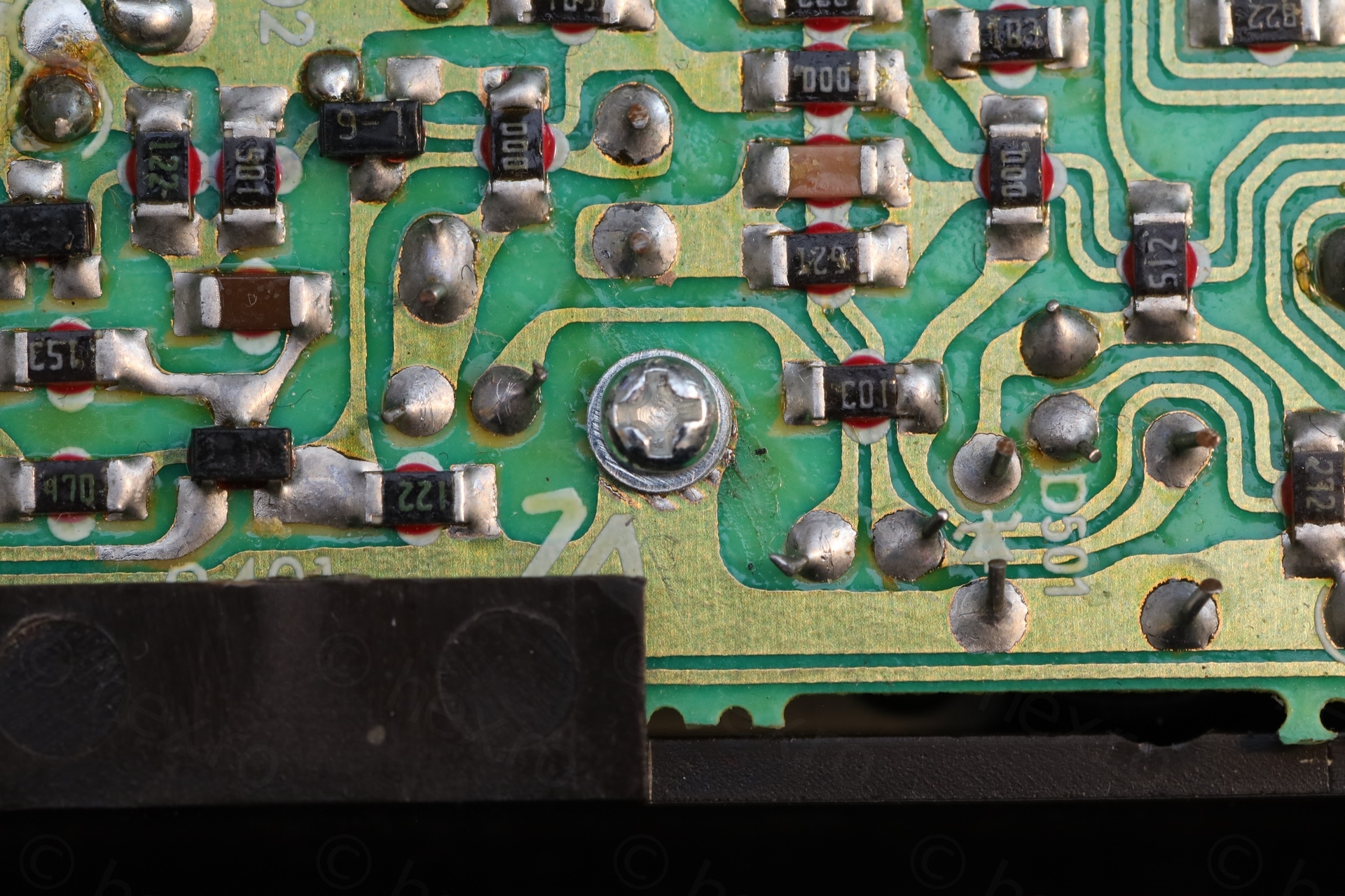
Last but not least, there was a screw missing that was supposed to hold the board attached to the chassis – but I didn’t have a short one. I improvised from a longer M2 screw:
Conclusion
A cute TV that had a very hard life. It is now fixed. Too bad it has distorted image, but it is a hefty mini TV 🙂
Leave a Reply