

Discovery
There’s something appealing in finding an old DIY device at the flea market.
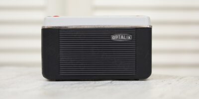
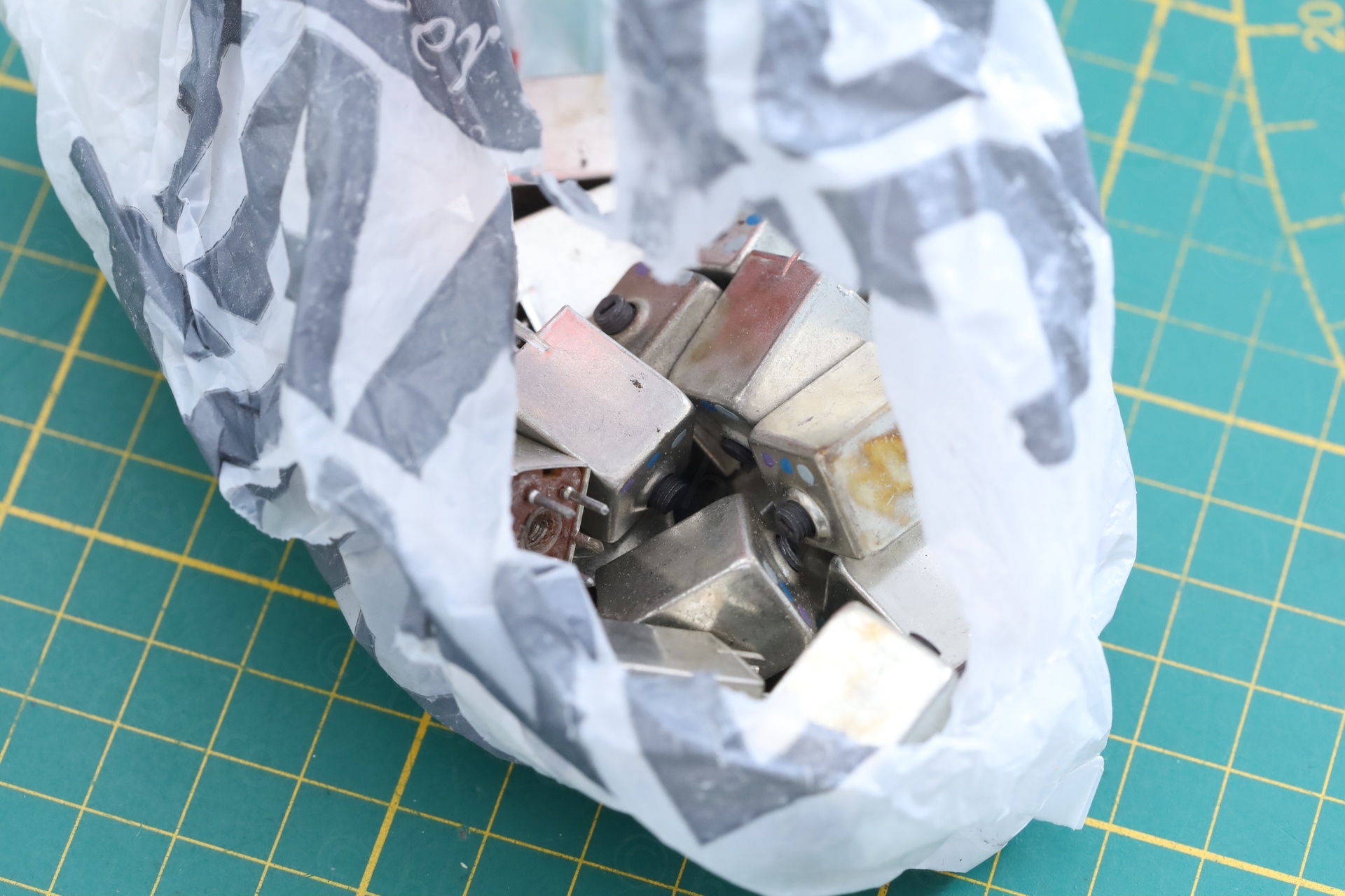
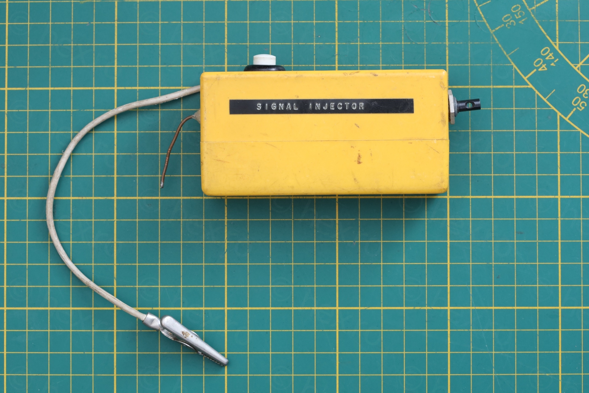
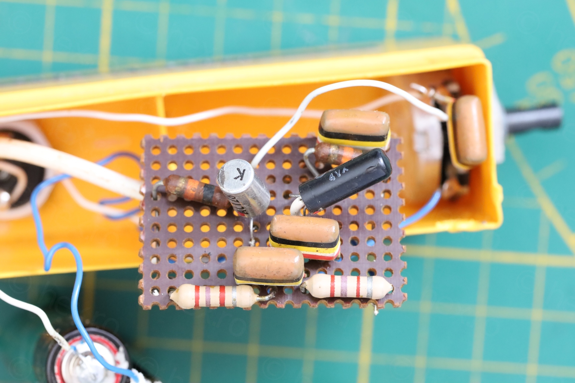
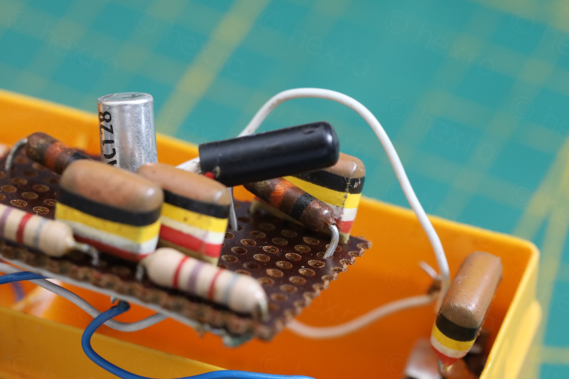
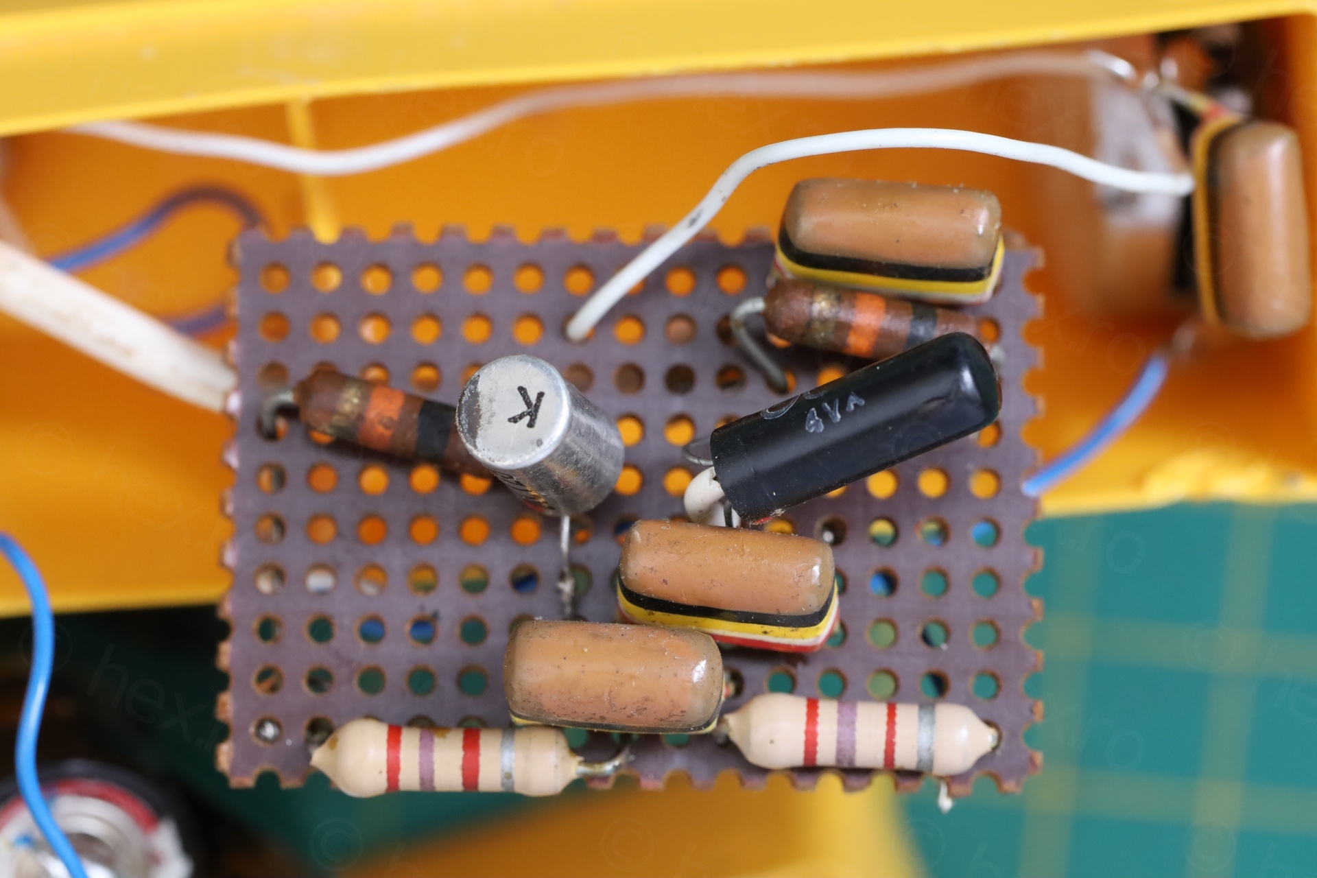
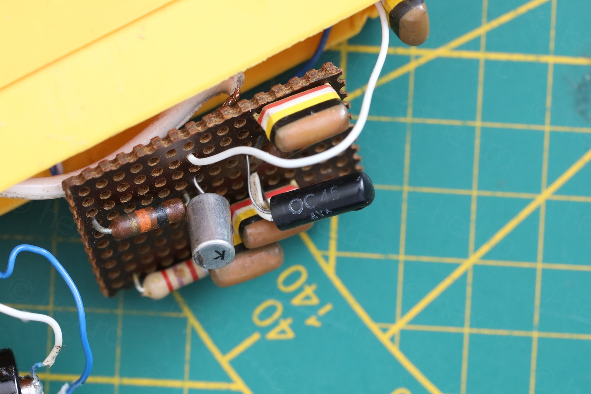
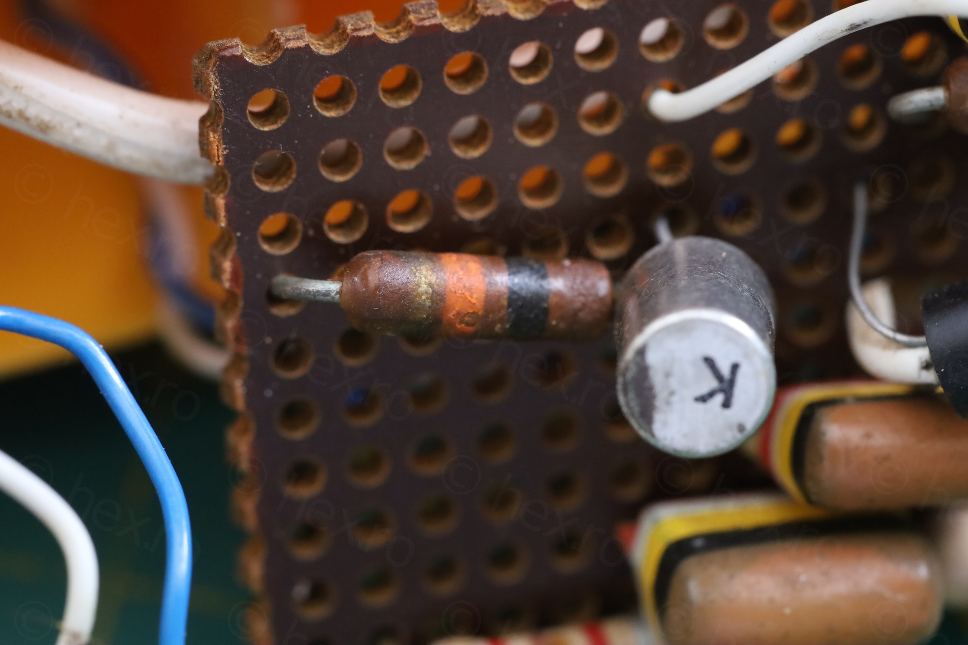
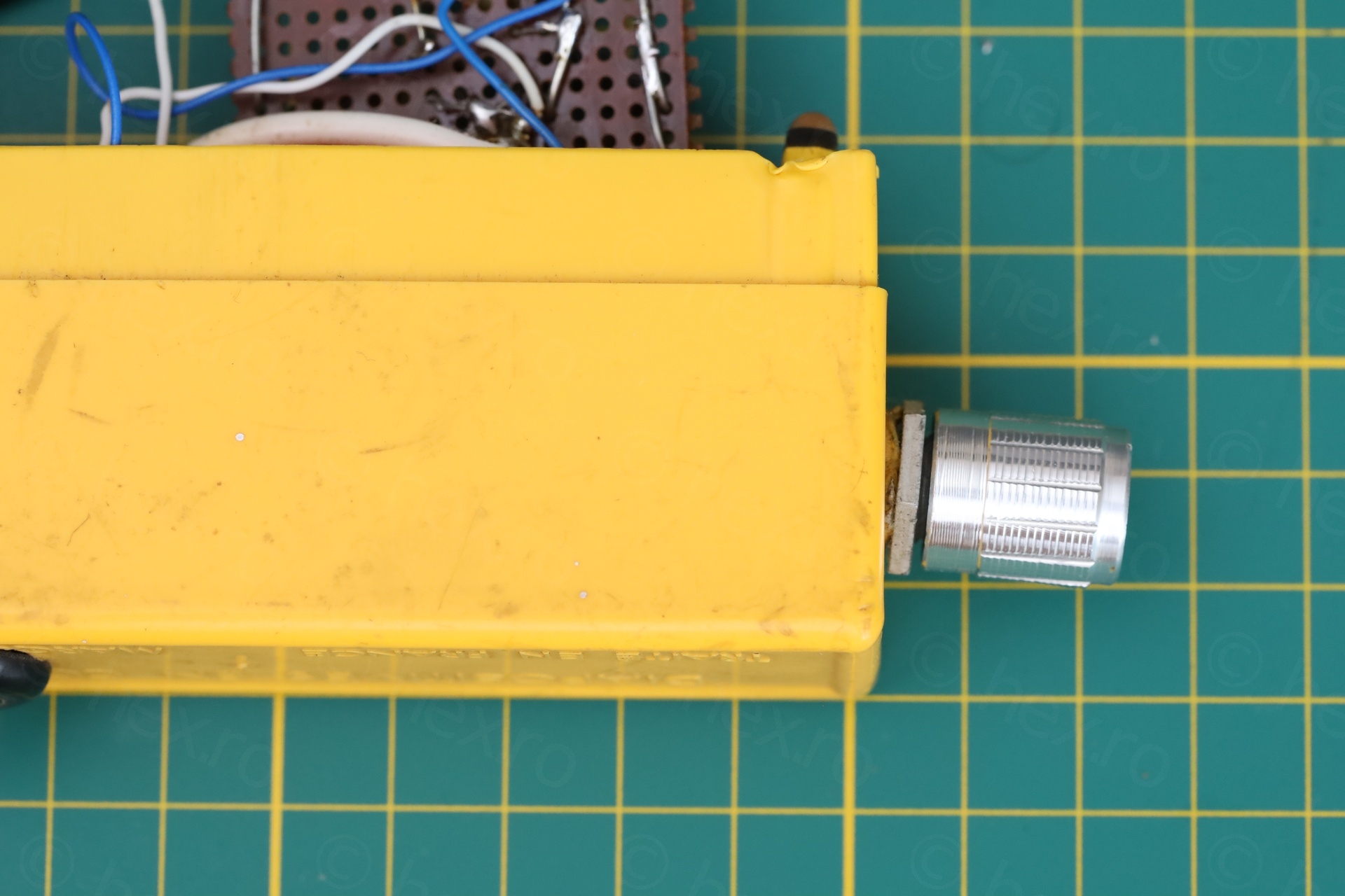
In an drawer put directly on the pavement, a bright yellow device catches my eye. I pull it out from the dirty plastic bag to have a look, it is labeled ‘SIGNAL INJECTOR’. Really ? It is not common to find such a thing. Opening it slowly, trying to make sense of it, there is a small circuit board and my eyes land on the first active component – a shiny Germanium transistor marked AC128. I had to have it.
The plastic bag also contains a LOT of IF cans – I wonder, how many radios did this person had to fix ?! Hmm. Anyway, negotiation was fast and here they are.
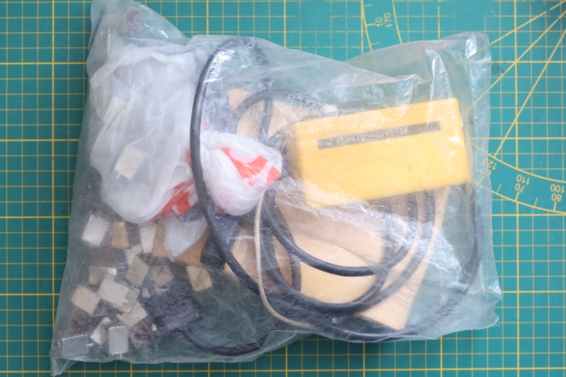
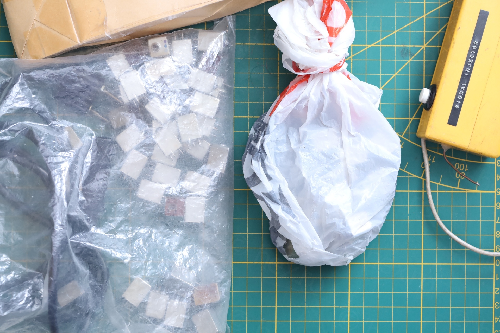
At home, it was obvious why so many inductors. I found an LC filter – most likely, the IF cans were used to create higher order filters. And found the call sign of a Ham Radio operator.. I decided to do my best and rescue the device.
Signal injector
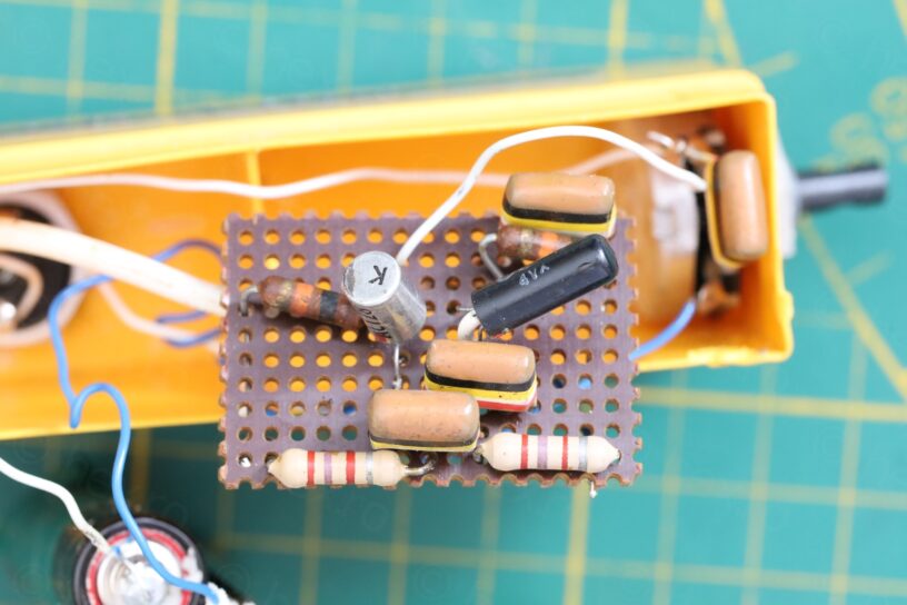
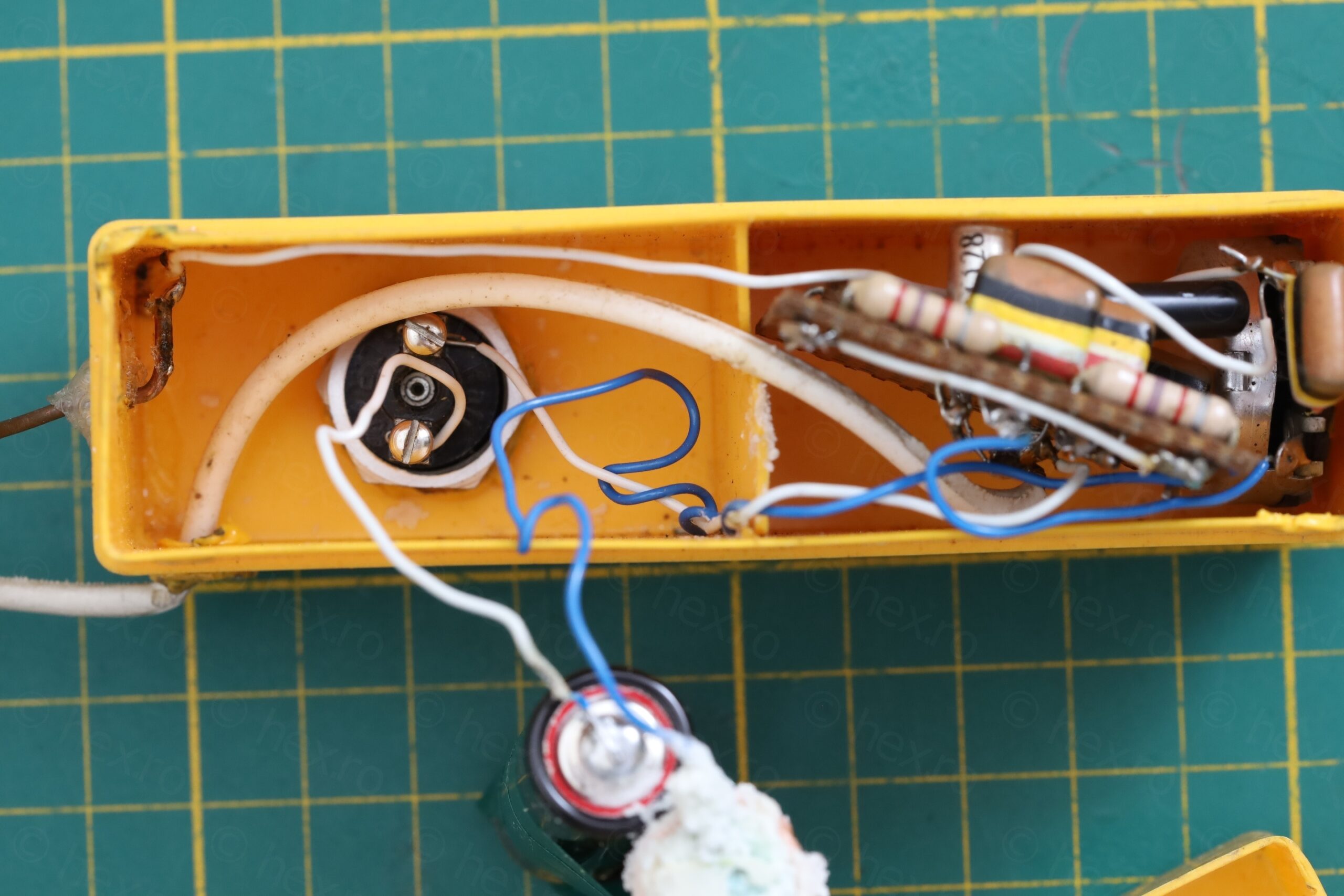
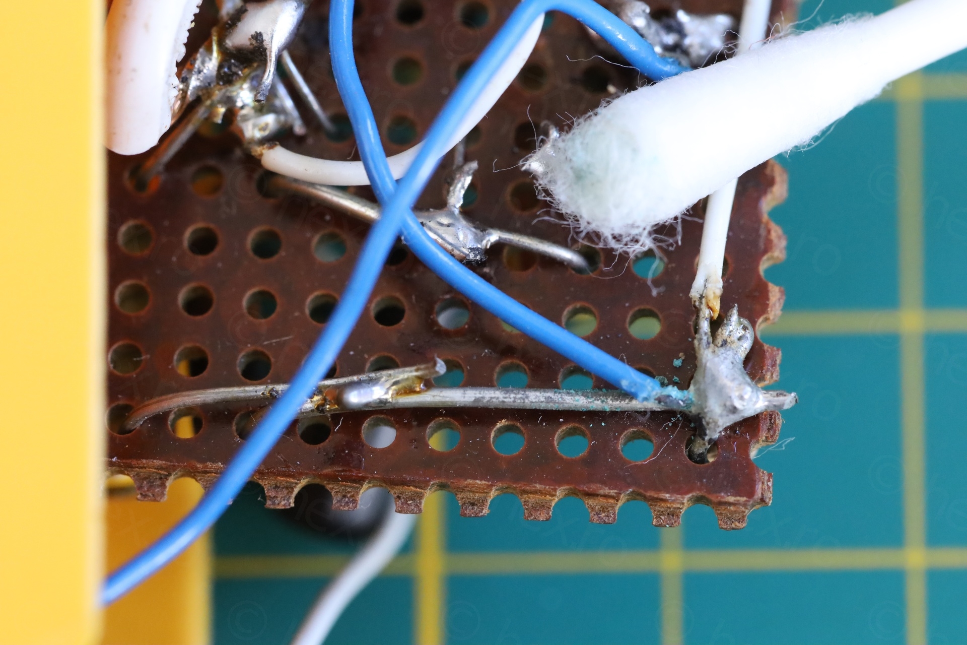
I took many photos of the innards, out of precaution. It was easy enough to do the simulation in LT Spice then to compare with the circuit itself. In case something didn’t work, I could fix it.
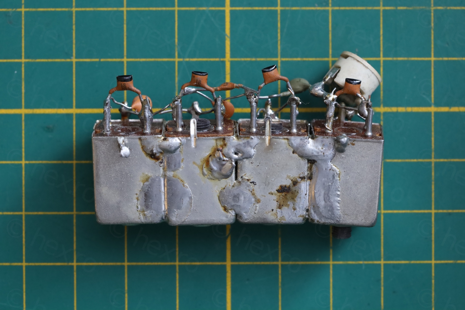
There were two corroded AA batteries inside and corrosion has reached the circuit board.

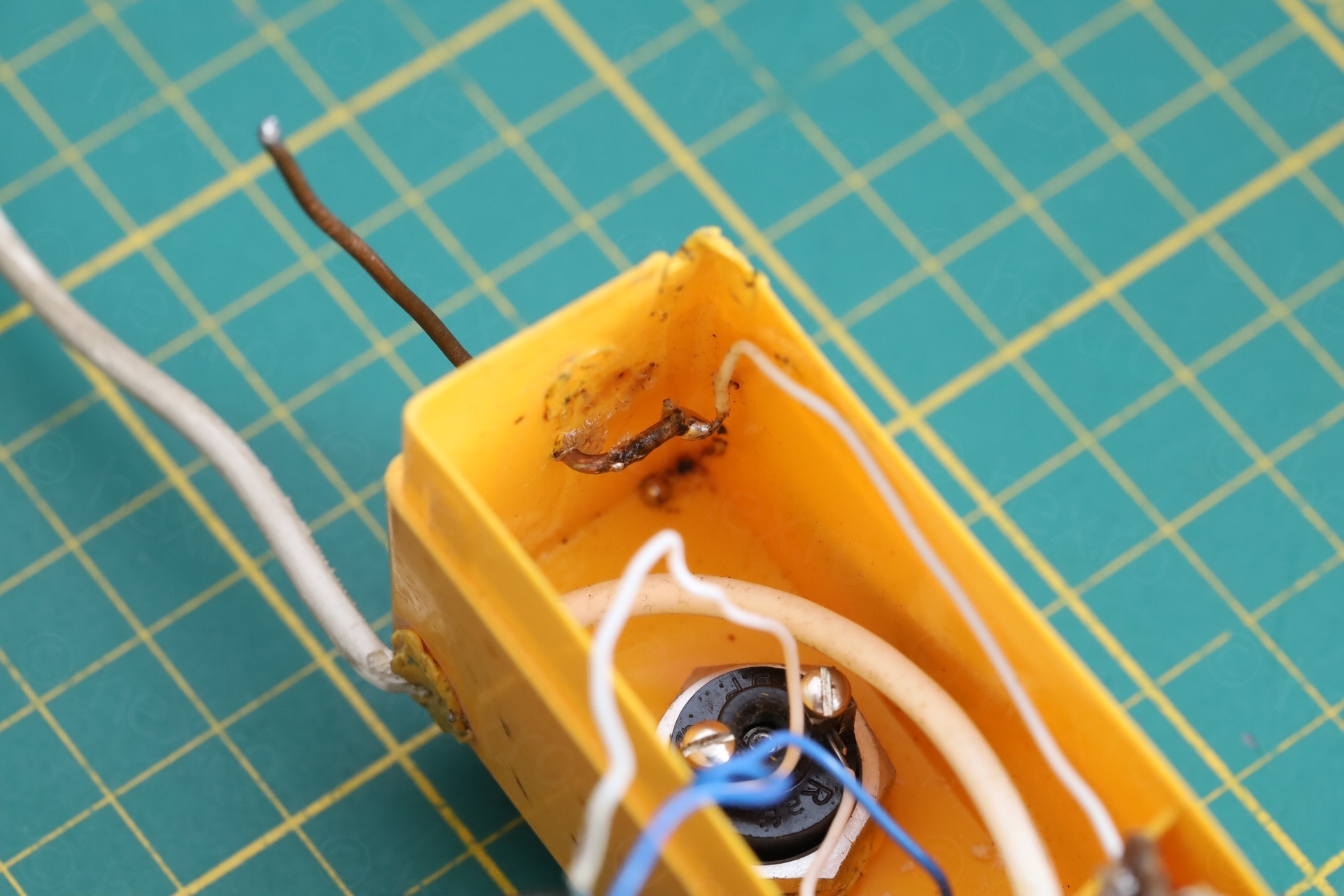
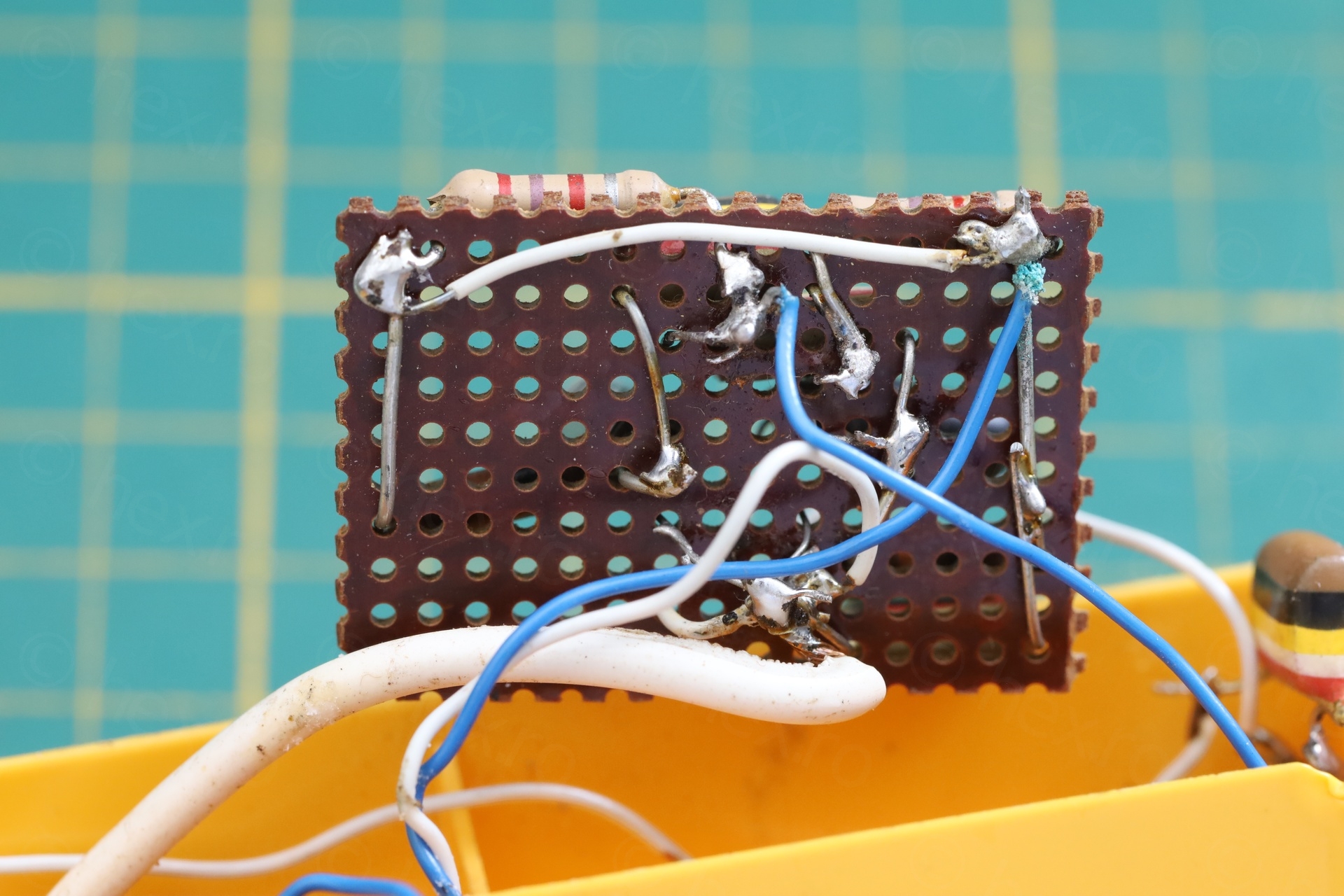
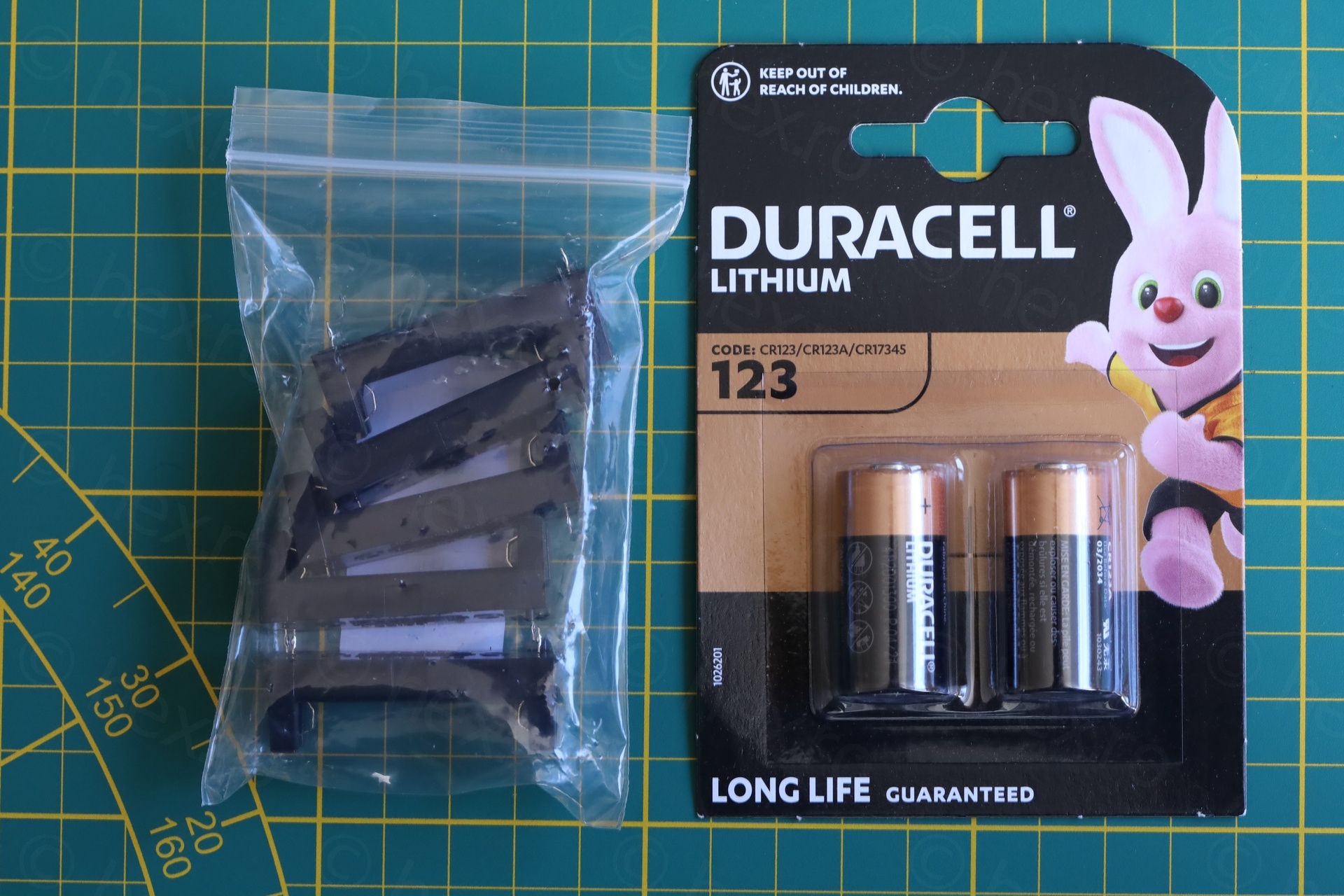
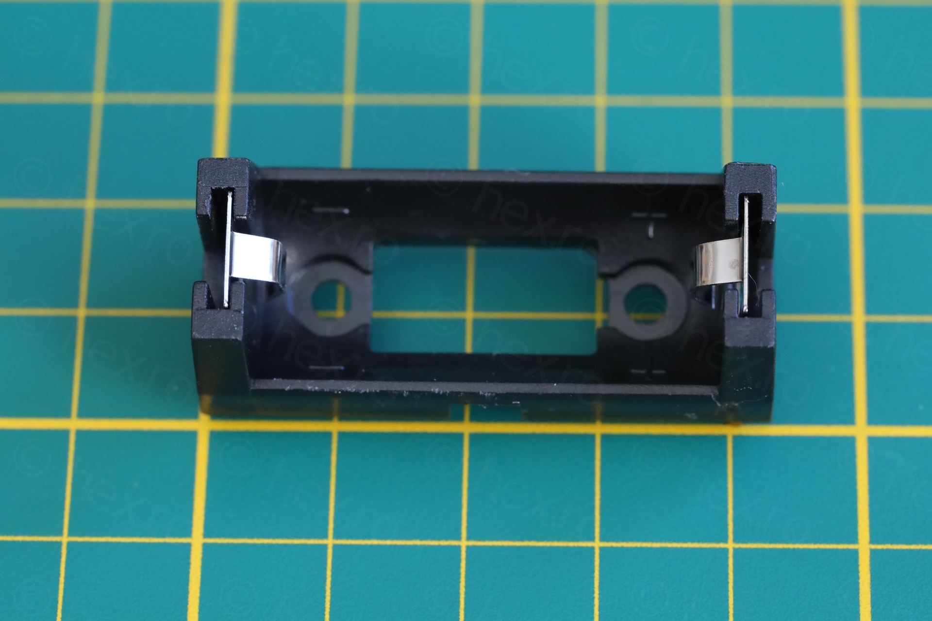
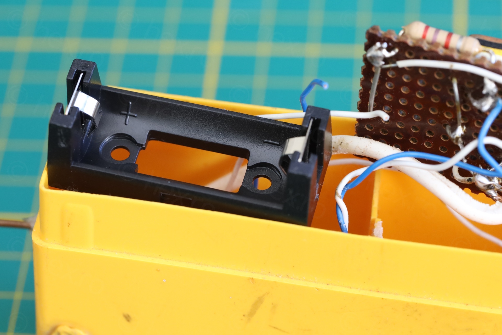
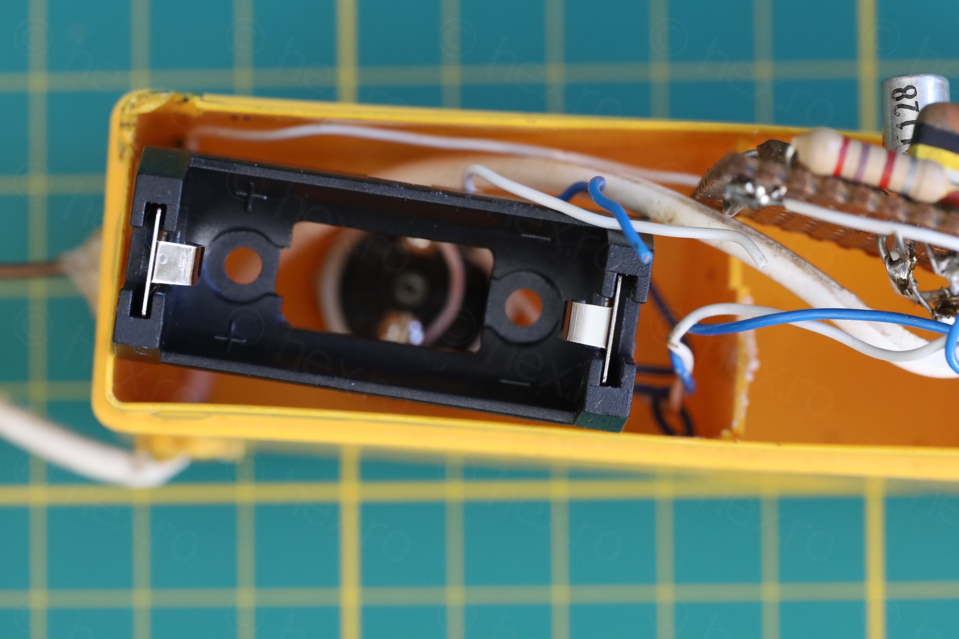
I cleaned up the corrosion, replaced one of the blue wires with a similar colored one (trying to preserve the original wiring color). There was no place to fit an 2xAA battery holder, so I went with a CR123 battery + its holder.
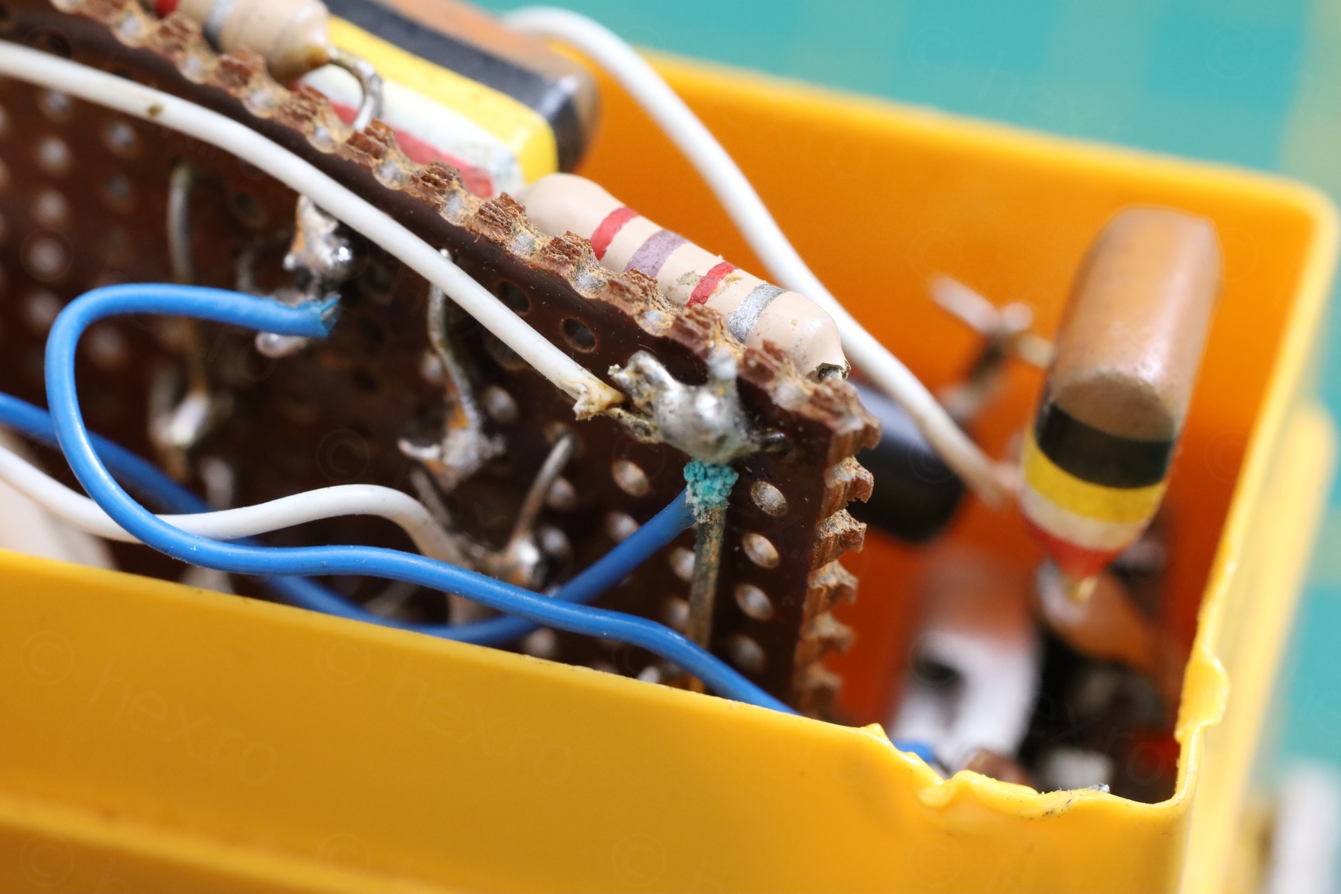
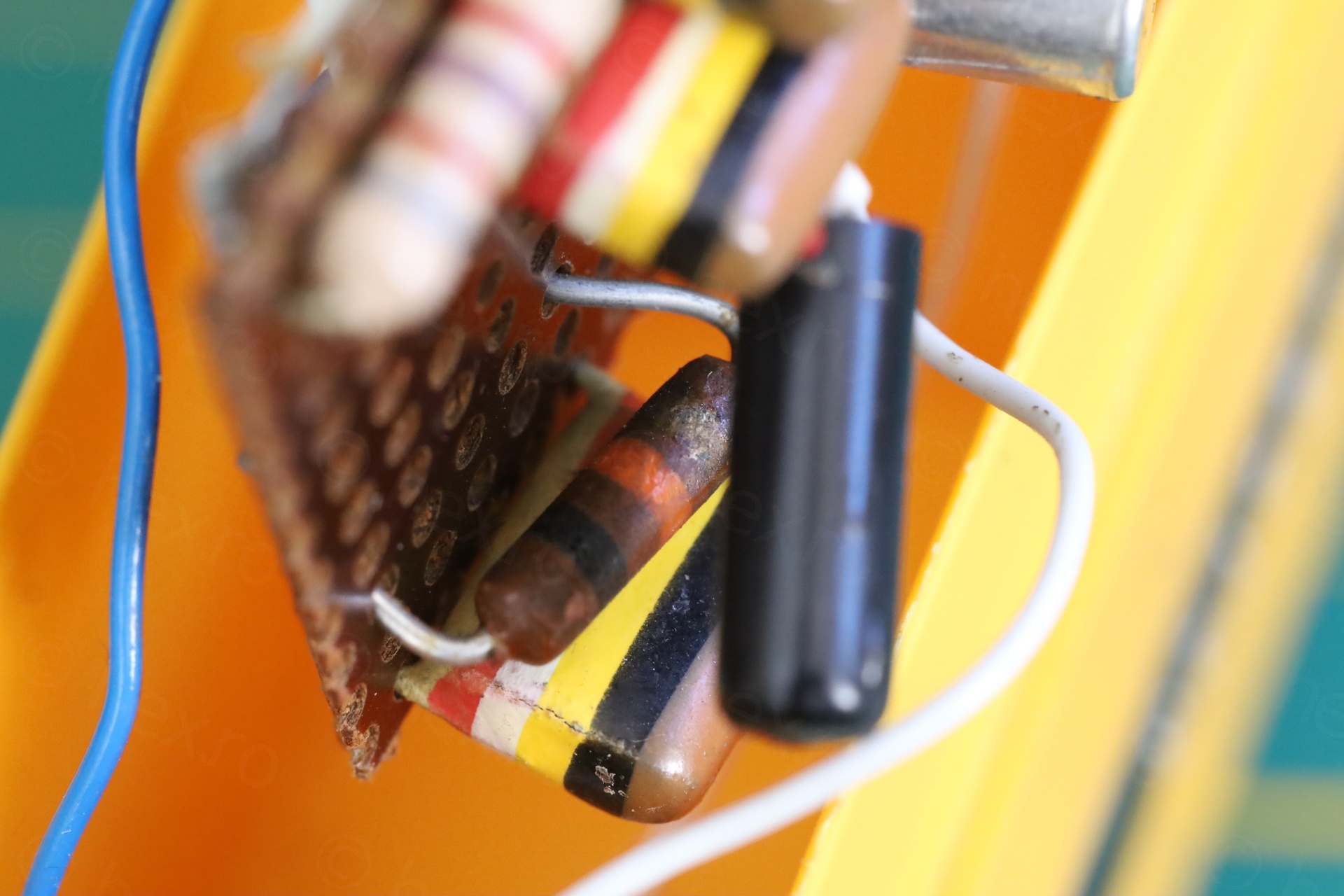
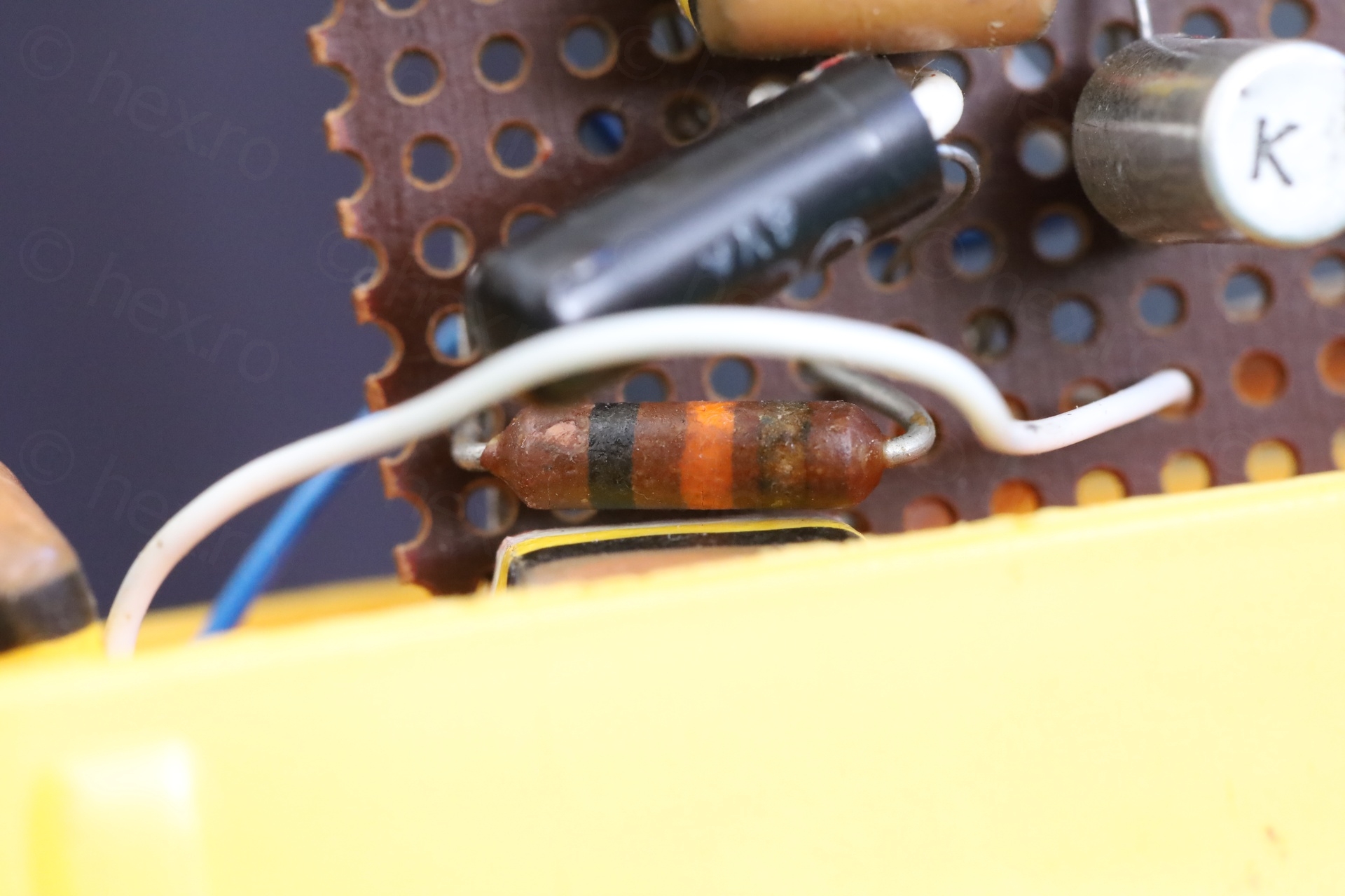
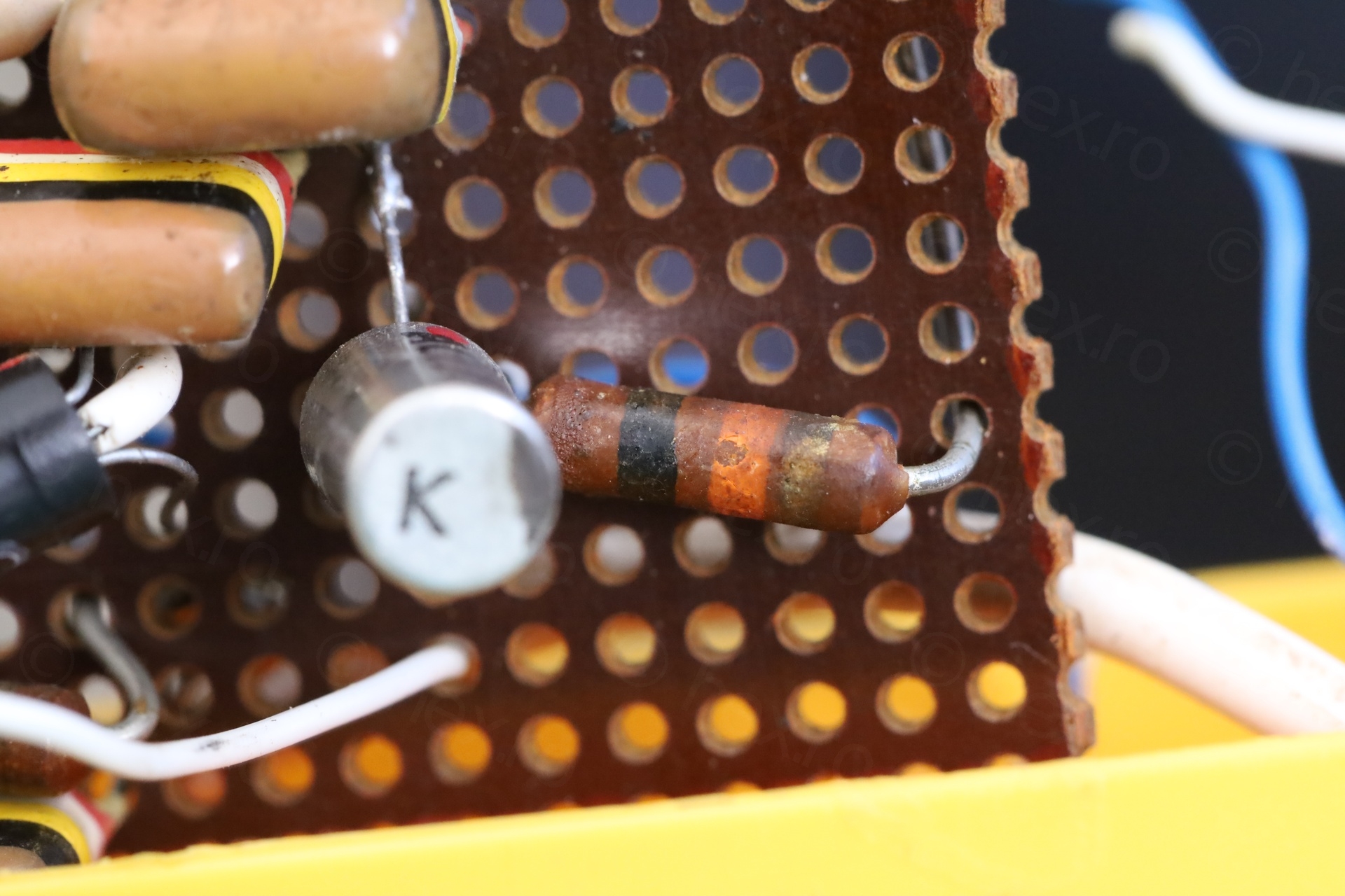
I could not decipher the value of the older style resistors – the color bands were not clear to my eyes. It would be good to know the approximation value to put it in the simulation.
After de-soldering one of connection points, I measured the resistances out of circuit:
a) the modern resistor one with bands Red Violet Red is measuring 2.75kΩ
b) the older style resistor, one with discolored bands, is measuring 11.13kΩ. I assume it is a 10kΩ 5% resistor (Brown Black Orange Gold bars)
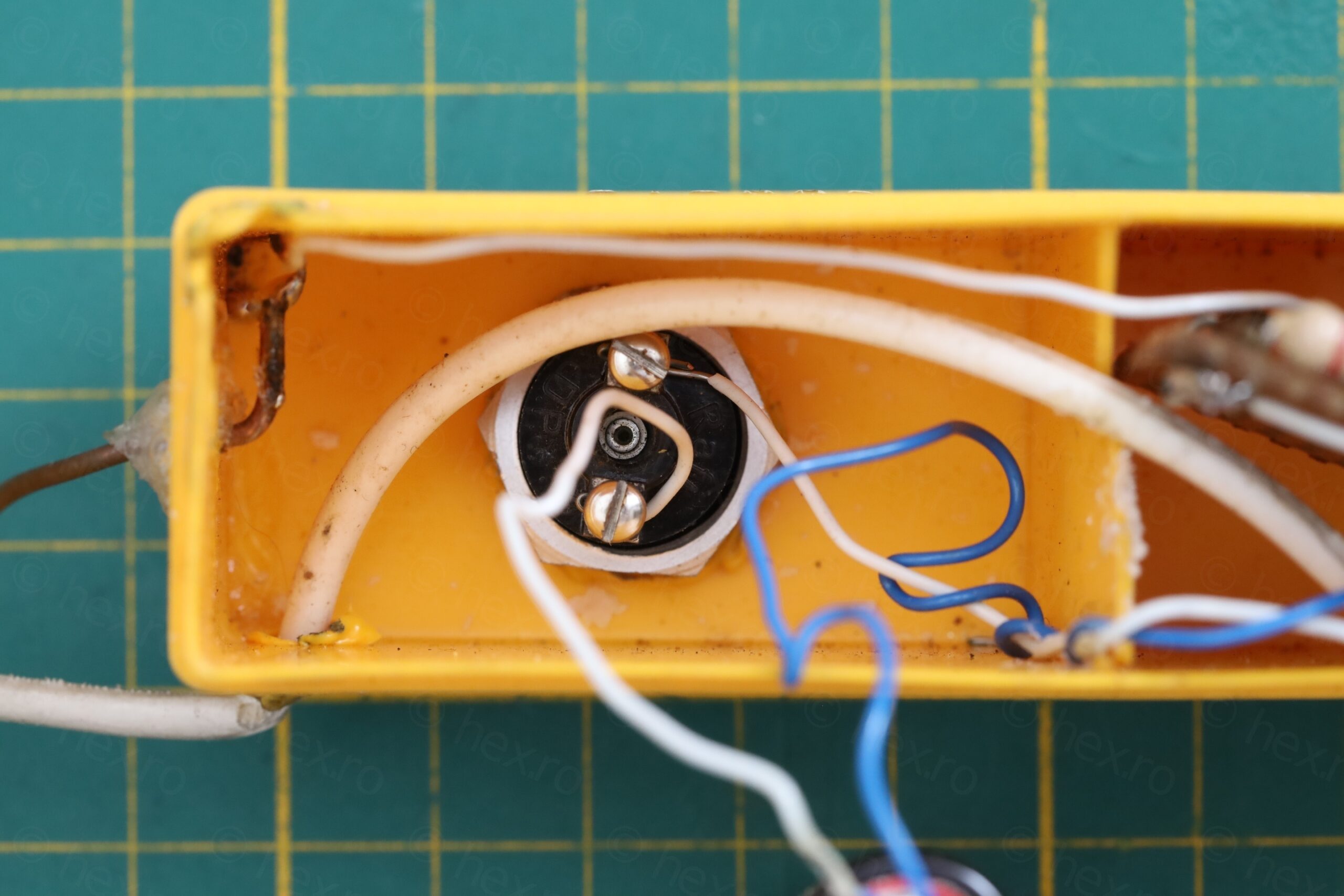
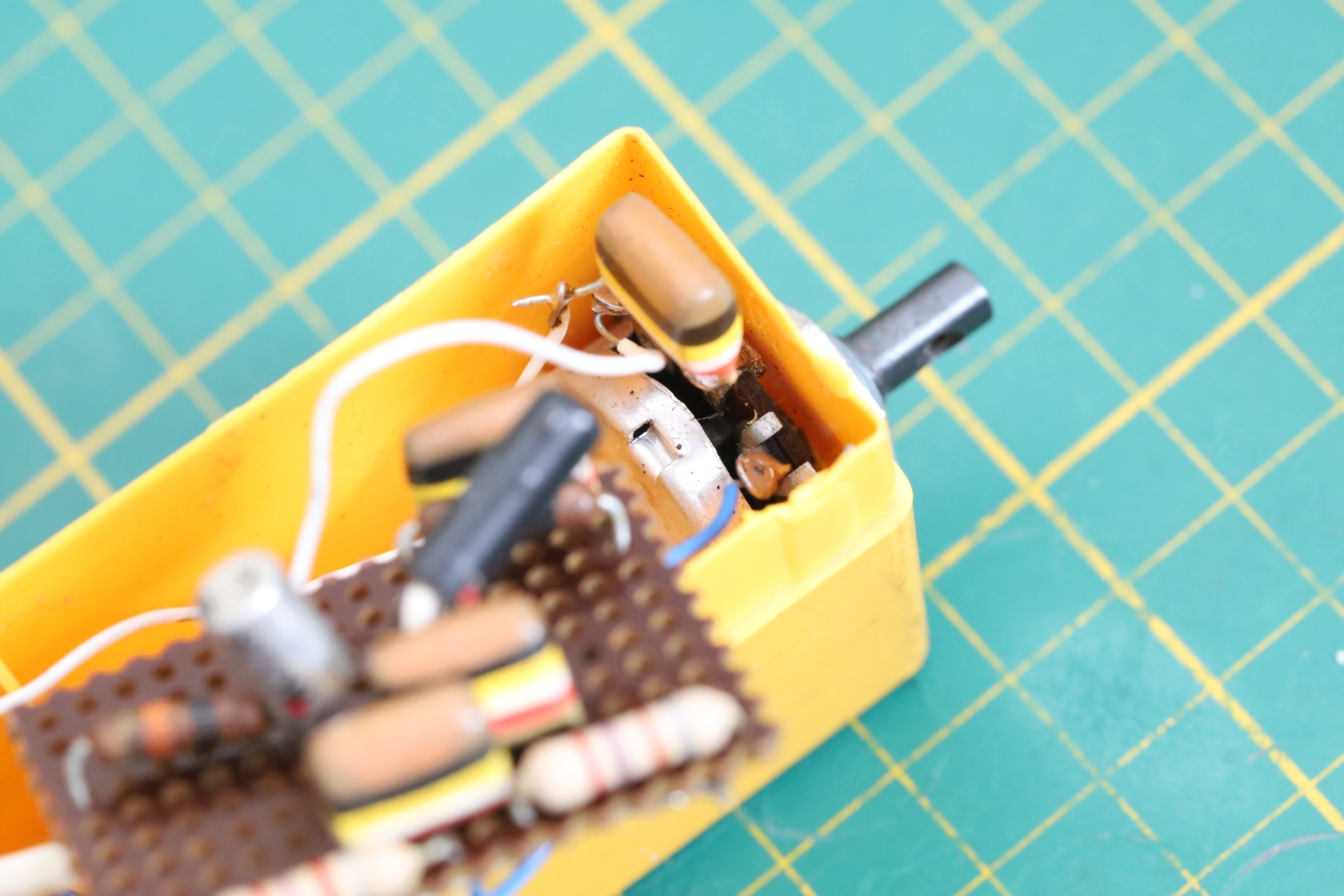
c) the pot, out of circuit, was measuring 98kΩ max and is logarithmic.
Found also a metallic knob that fitted over the pot:
It works, I didn’t have to fix anything.
Schematic
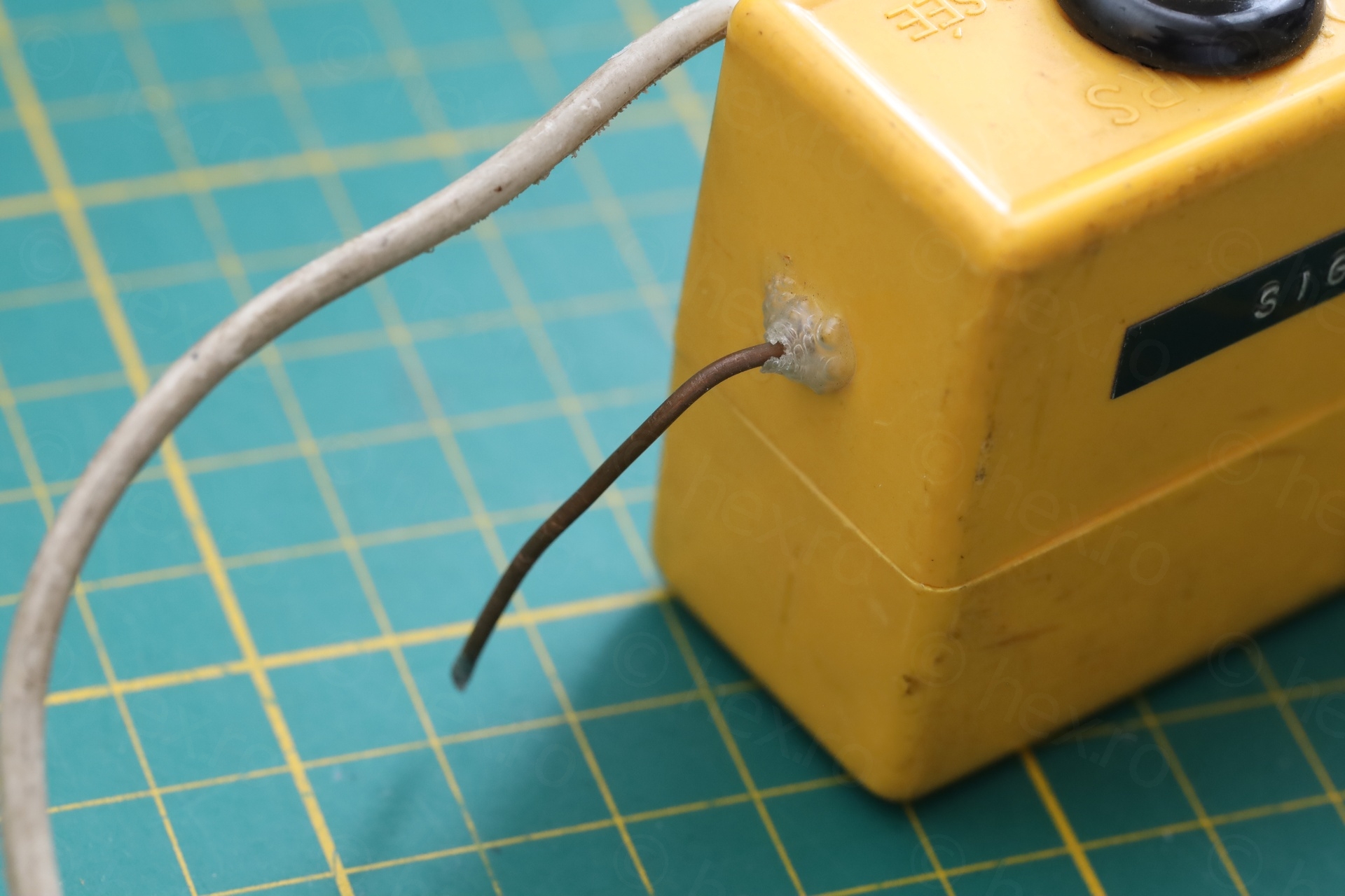
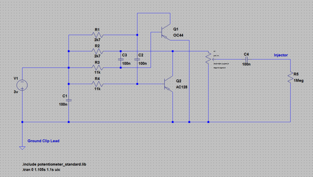
It is a classic astable multivibrator built with an AC128 + OC44 PNP Germanium transistors. Battery positive sits at the ground clip lead. The capacitors are supposed to be 100nF @ 250V – there’s even one across the battery connectors.
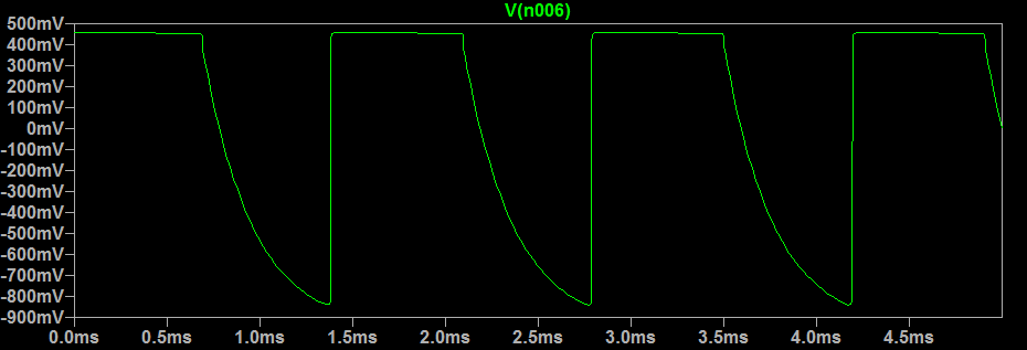
I recreated the schematic in LT Spice and compared it with the oscilloscope results. Almost identical. The injector output is decoupled with a capacitor too, and signal is picked from the wiper of the pot. The R5 / 1Meg represents the Oscilloscope Input:
Simulation results:
Oscilloscope measurement (DS203, pot turned to the maximum):
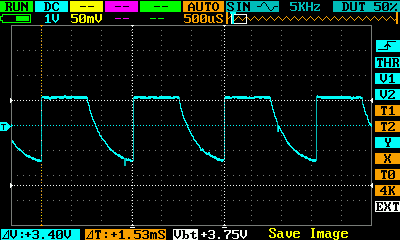
It oscillates at around 654Hz.
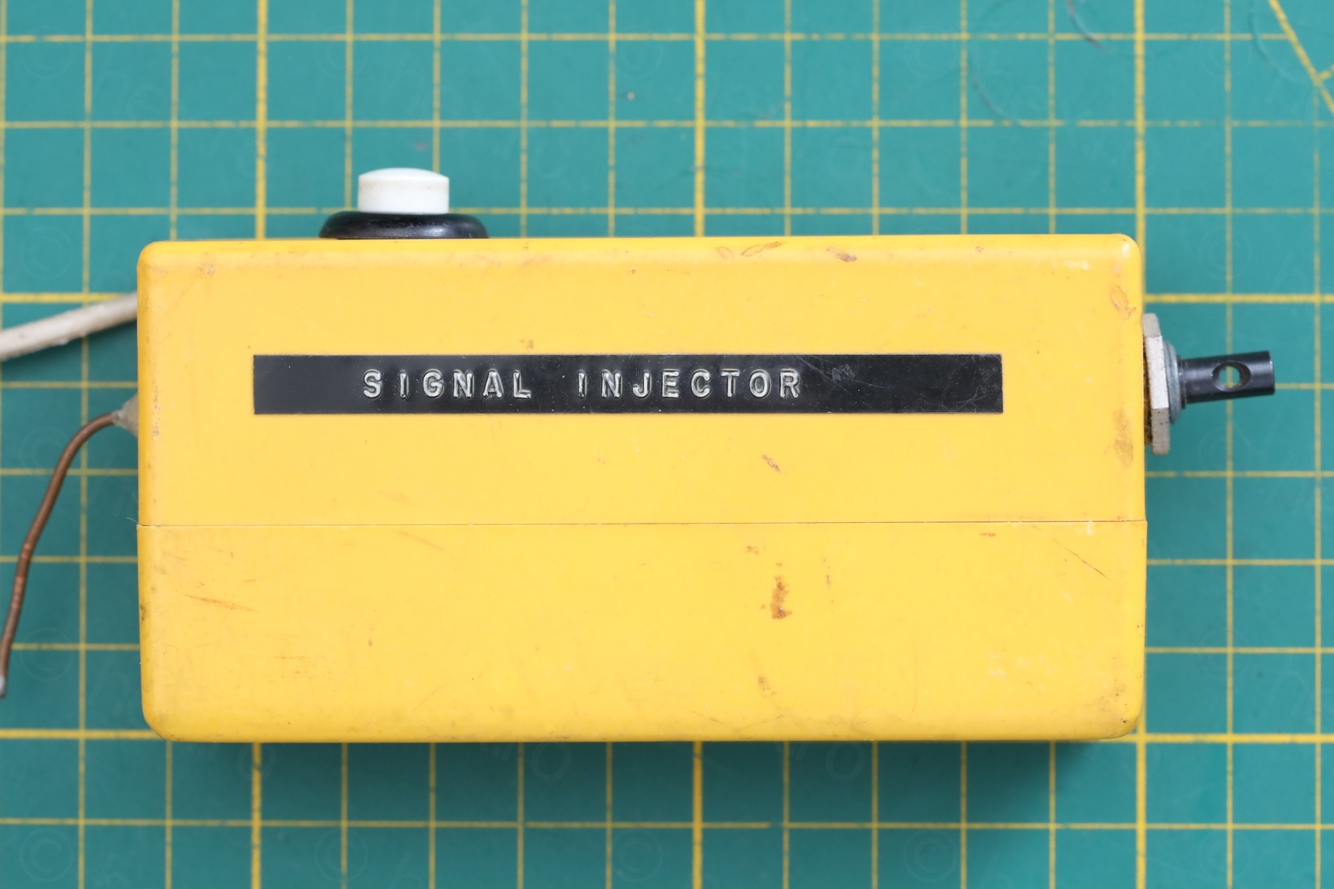
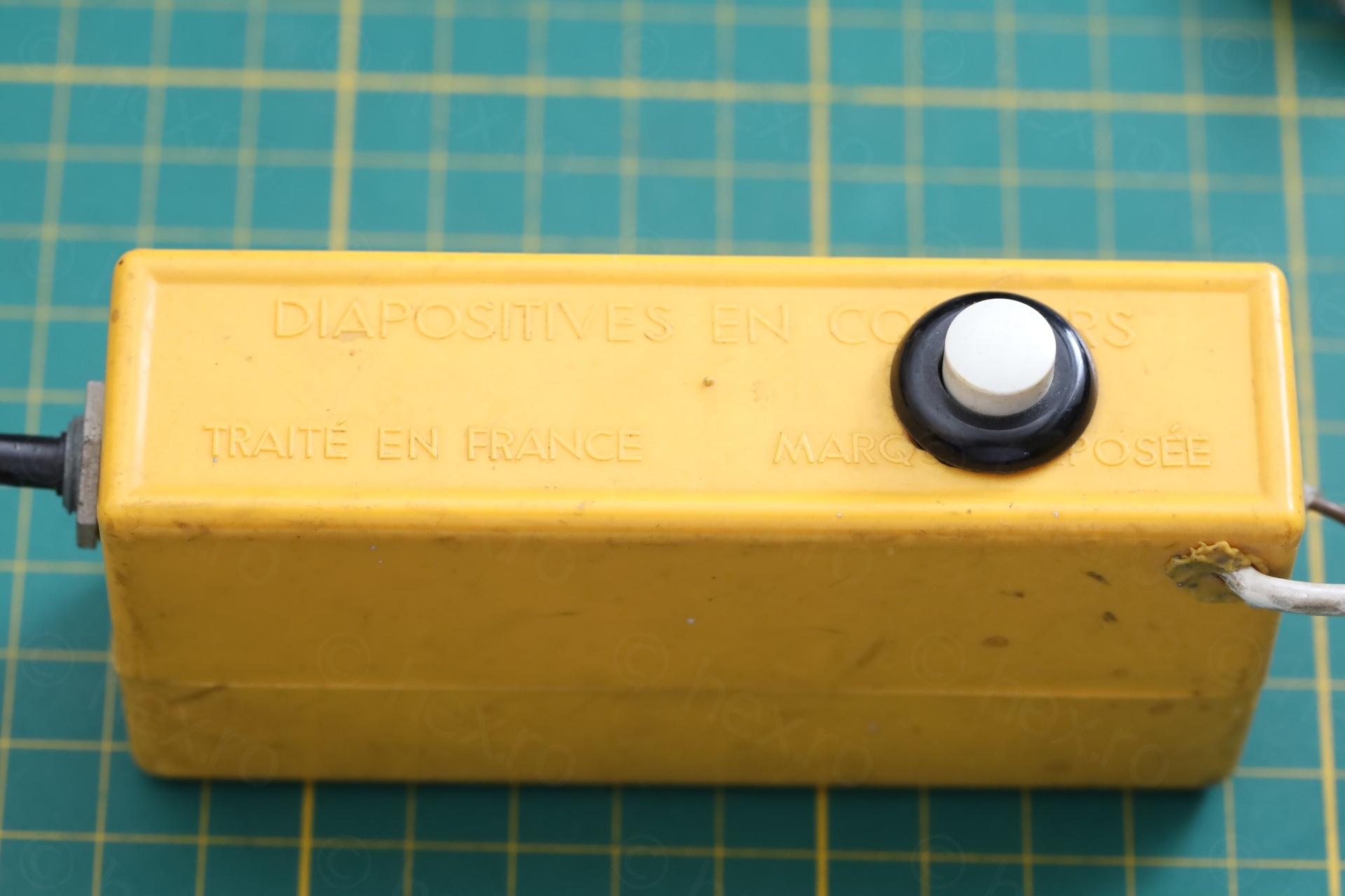
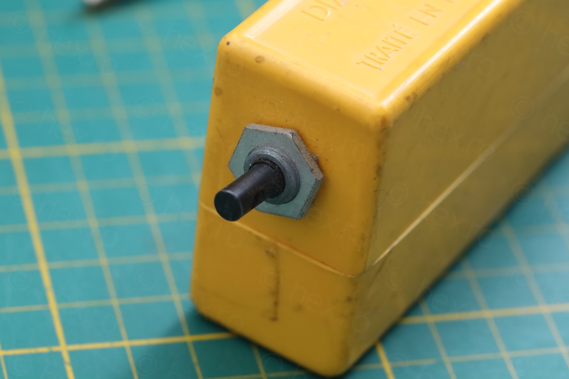
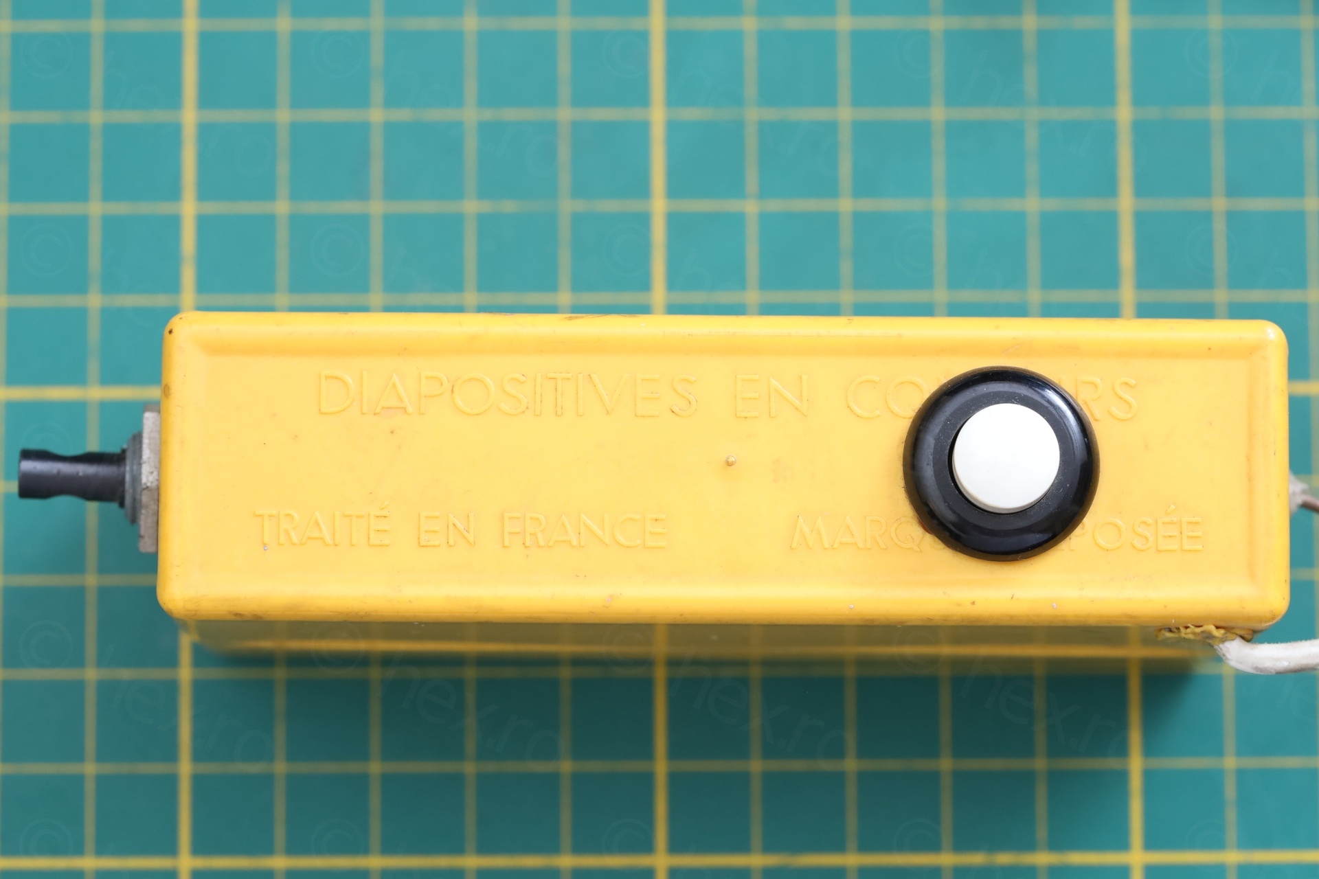
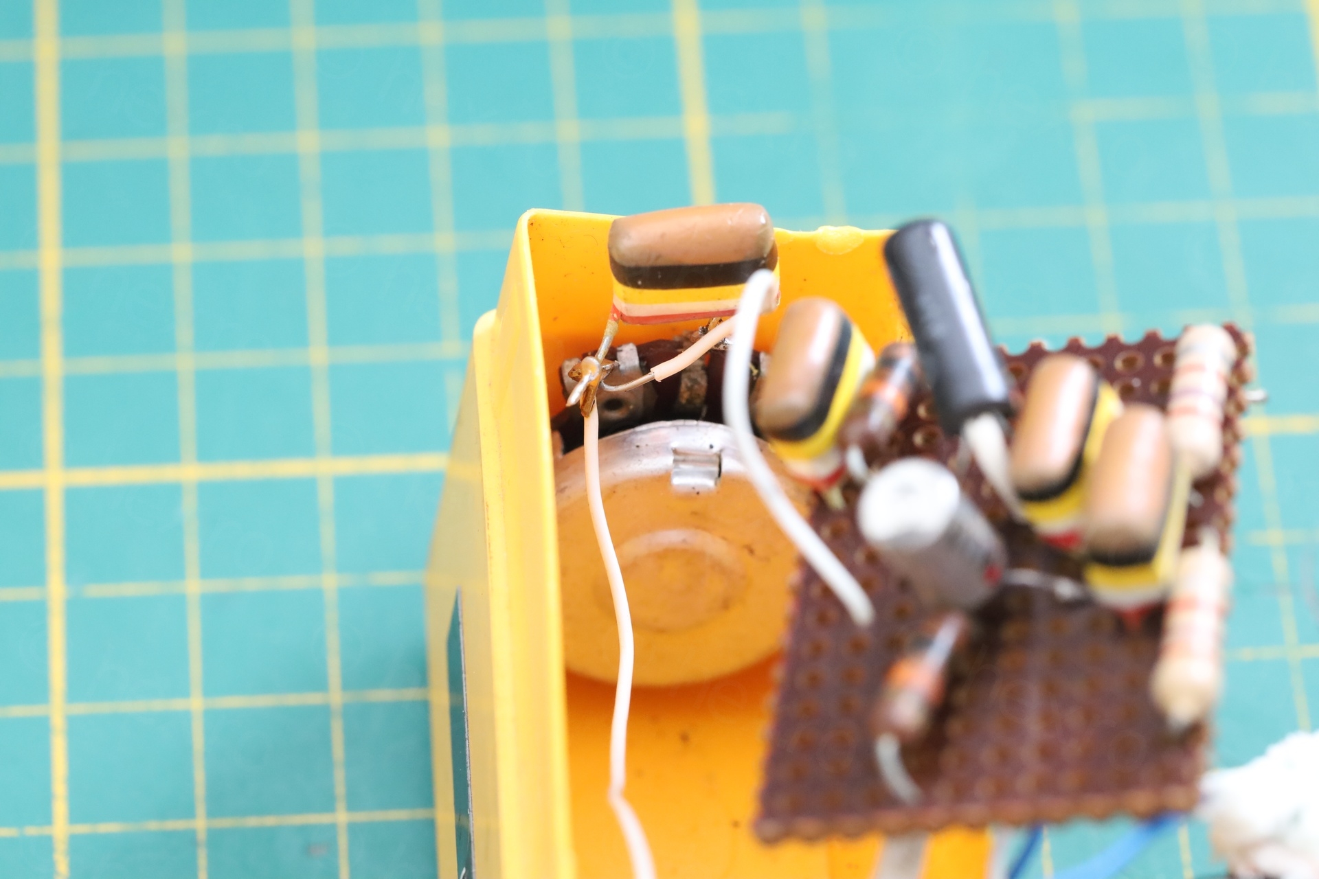
The project box is an old slides holder – and thought has been put when assembling the project: the decoupling output capacitor, the capacitor across battery terminals, using a potentiometer to adjust the output level, the ergonomics of the ON/OFF push-button.
It is something I wanted to build since I got the SE-250C – I didn’t give up the idea, but I am a little less motivated now. Happy to have found this bit of Electronics history so I will keep it as is. A perfectly usable device, hand made – hopefully it was used to fix many radios / amplifiers.
Leave a Reply