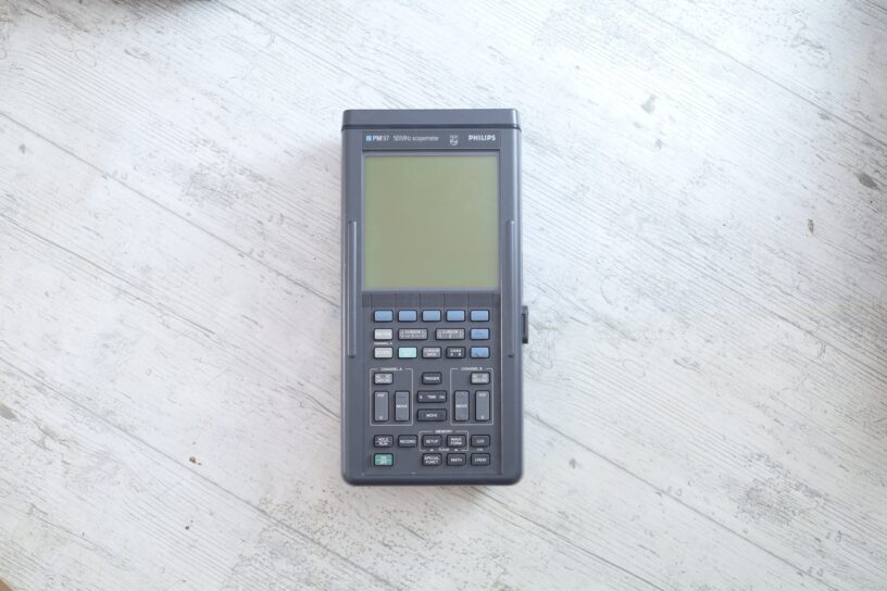
I spotted this online listing, an affordable Philips PM97 50MHz Scopemeter described as in working condition. There was something off with the announcement. A single photo underexposed noisy photo, the oscilloscope was not even in the center. Some cables and plugs, what appeared to be one or two probes … rather bleak sensation looking at the single photo.
I manage to win the bid as … nobody else tried.
Table of Contents
- Introduction
- Battery Corrosion
- Replacing dead capacitors
- Some buttons don’t work
- DIY Power Supply
- Testing
Introduction
I was on the lookout for the cheapest Fluke / Philips PM97 oscilloscope. I needed one to practice changing the electroluminescent backlight.
The package arrived, and I opened it. Everything was thrown in the carton box and shipped without any padding. While the original photo did not show the holster, it was in the package, but it did not survive the shipping. Chunks of yellow plastic were scattered on the bottom. The photo below is taken much later, after I manage to superglue the holster back together:
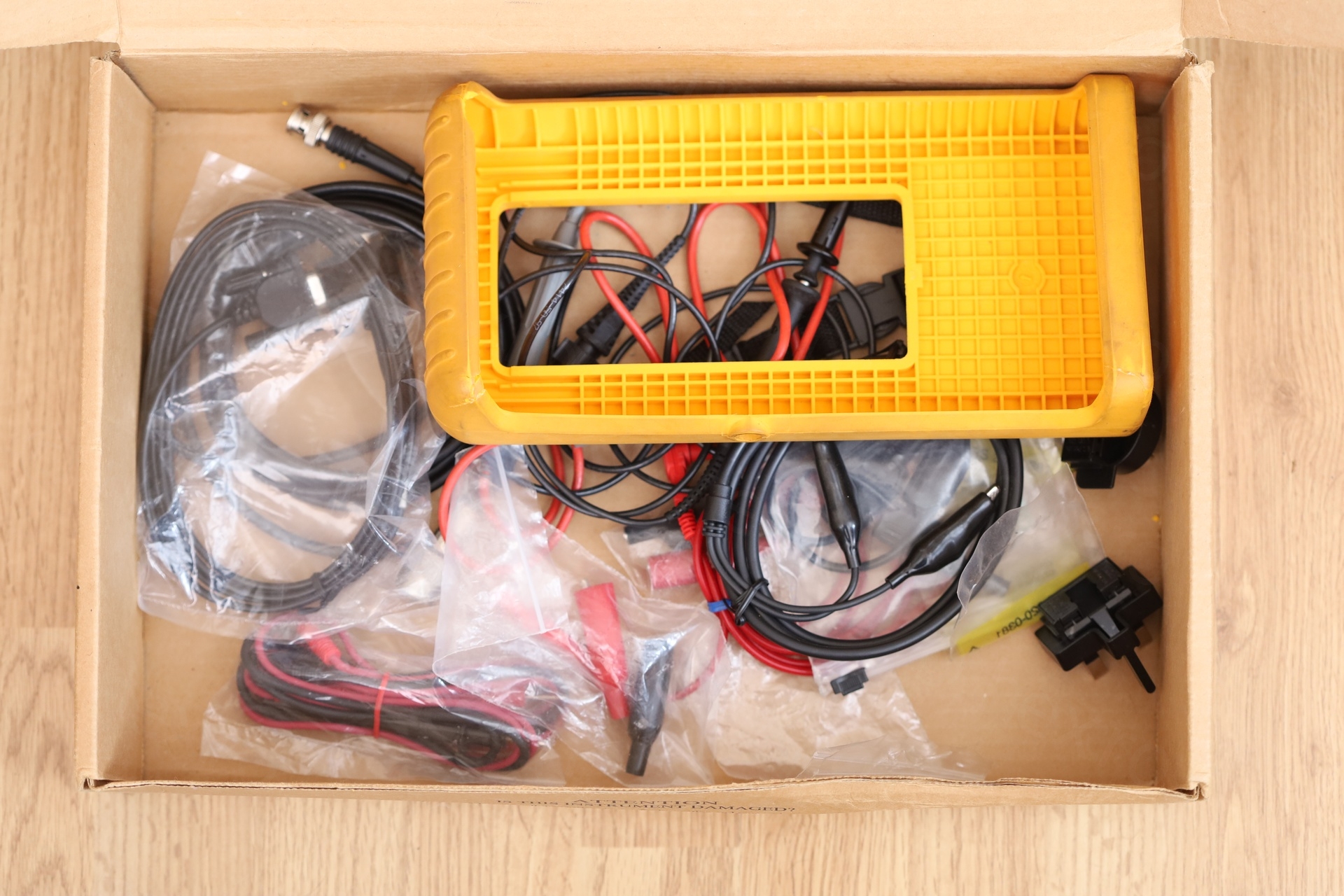
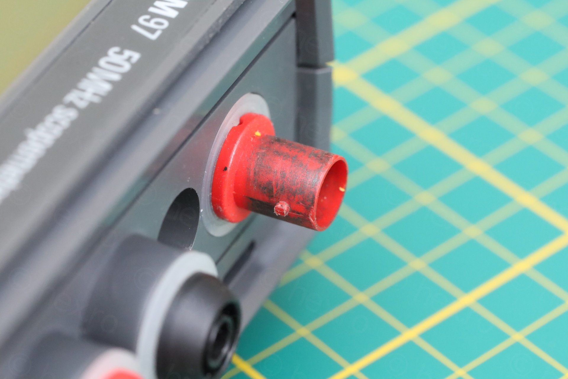
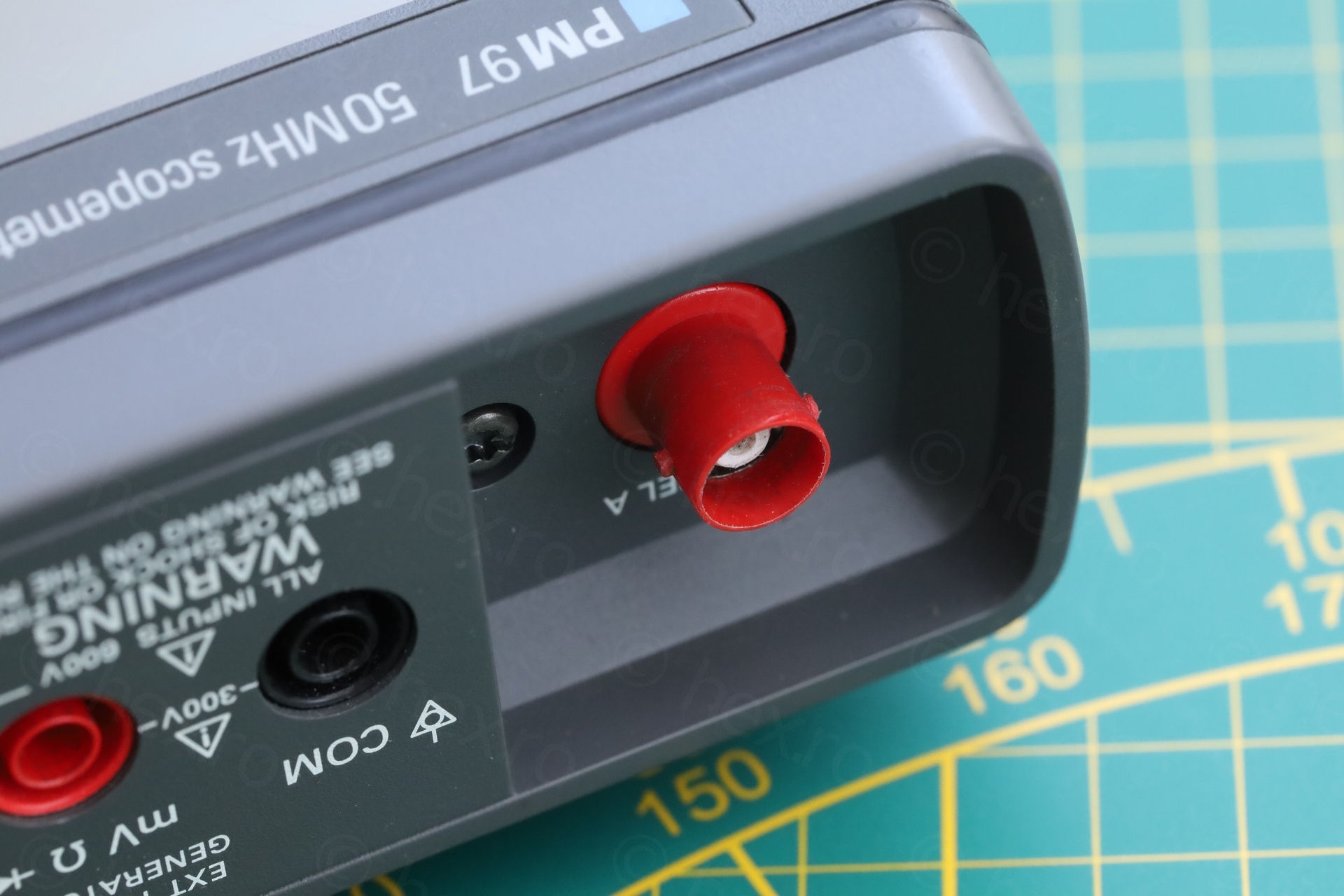
The probes were incomplete. The Philips one is missing the hat, the Tektronix one is missing the ground lead.. The lack of care in packaging felt revolting. Goal was an oscilloscope to practice on, so I consoled myself that everything else was just bonus. Also, relieved that the oscilloscope itself was present! The announcement, the bidding without bidders, the single blurry photo, I had some doubts that I’ll get it.
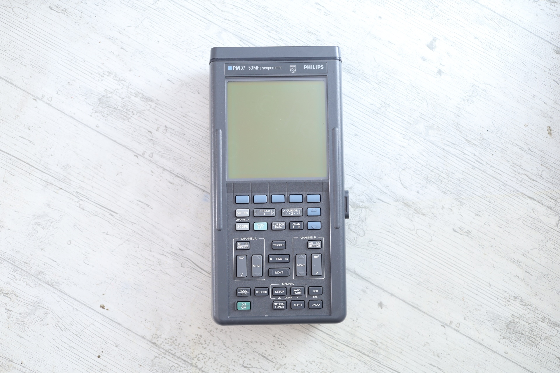
The oscilloscope itself looked fine at first sight but it happiness was short lived.
It turned on, I saw the meter image appearing, but just out of the blue it turned off. And it stayed off. It failed to respond to any attempt at turning it back on again.
Battery Corrosion
The meter felt heavy, is there a battery that could prevent it from starting up ?
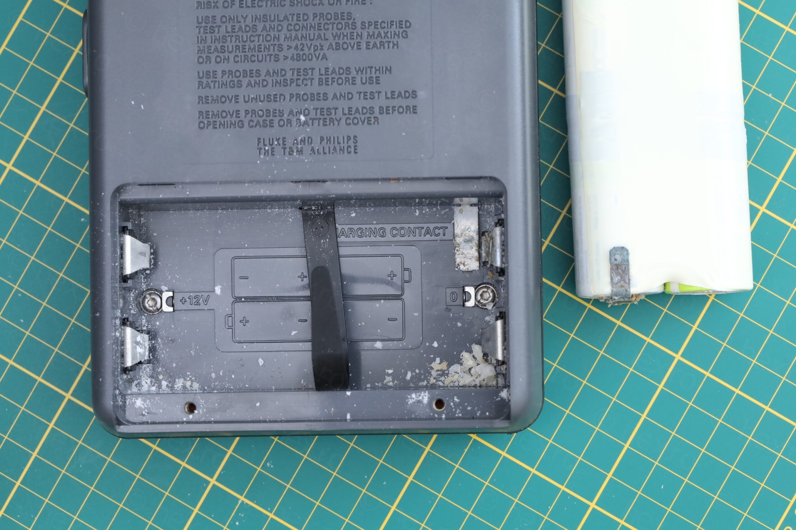
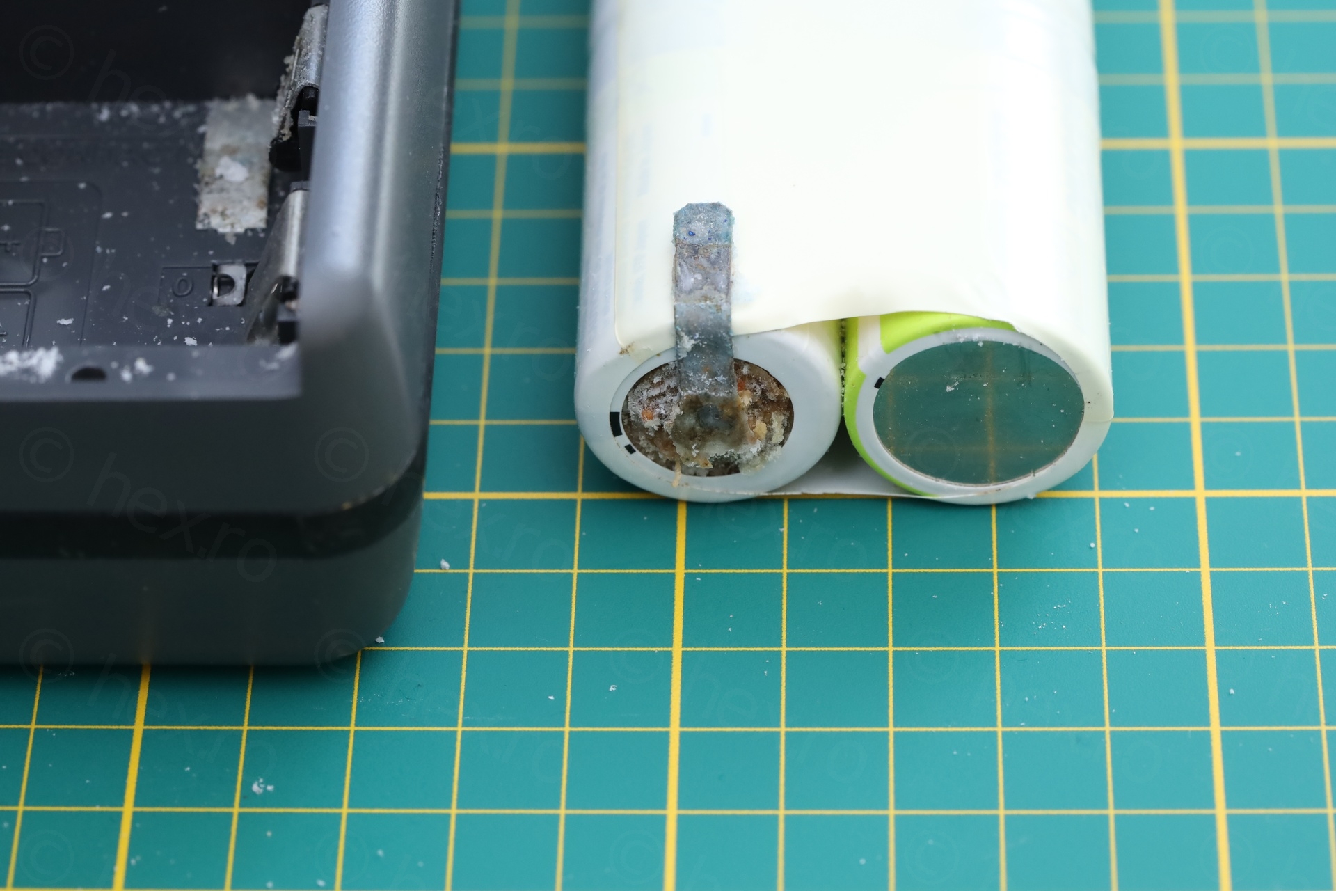
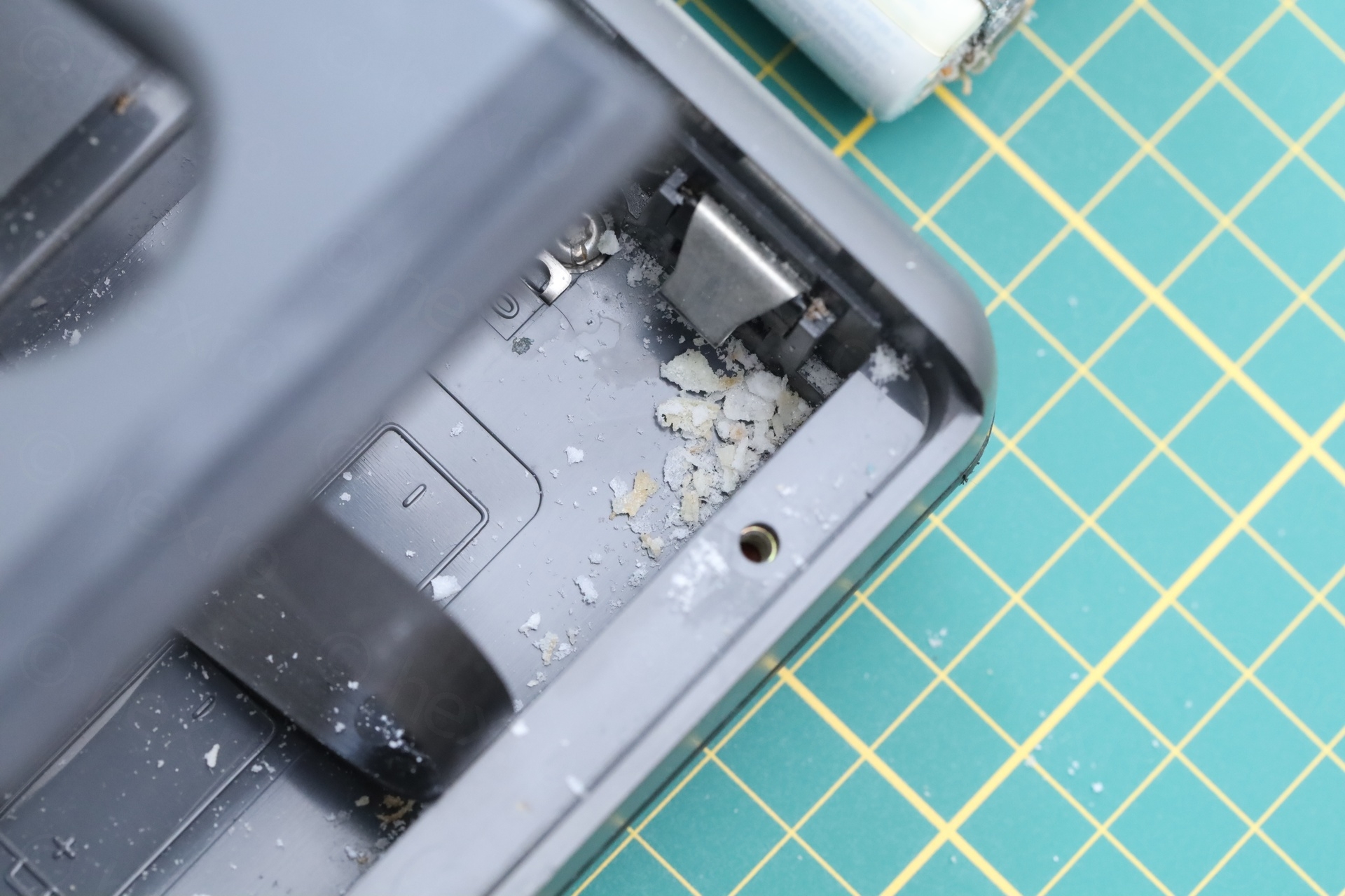
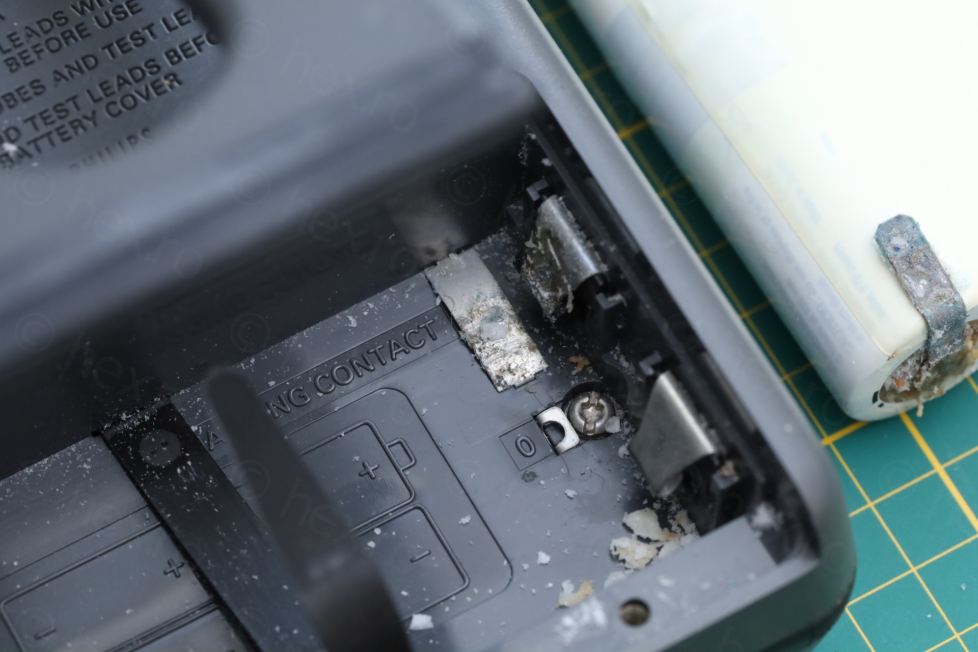
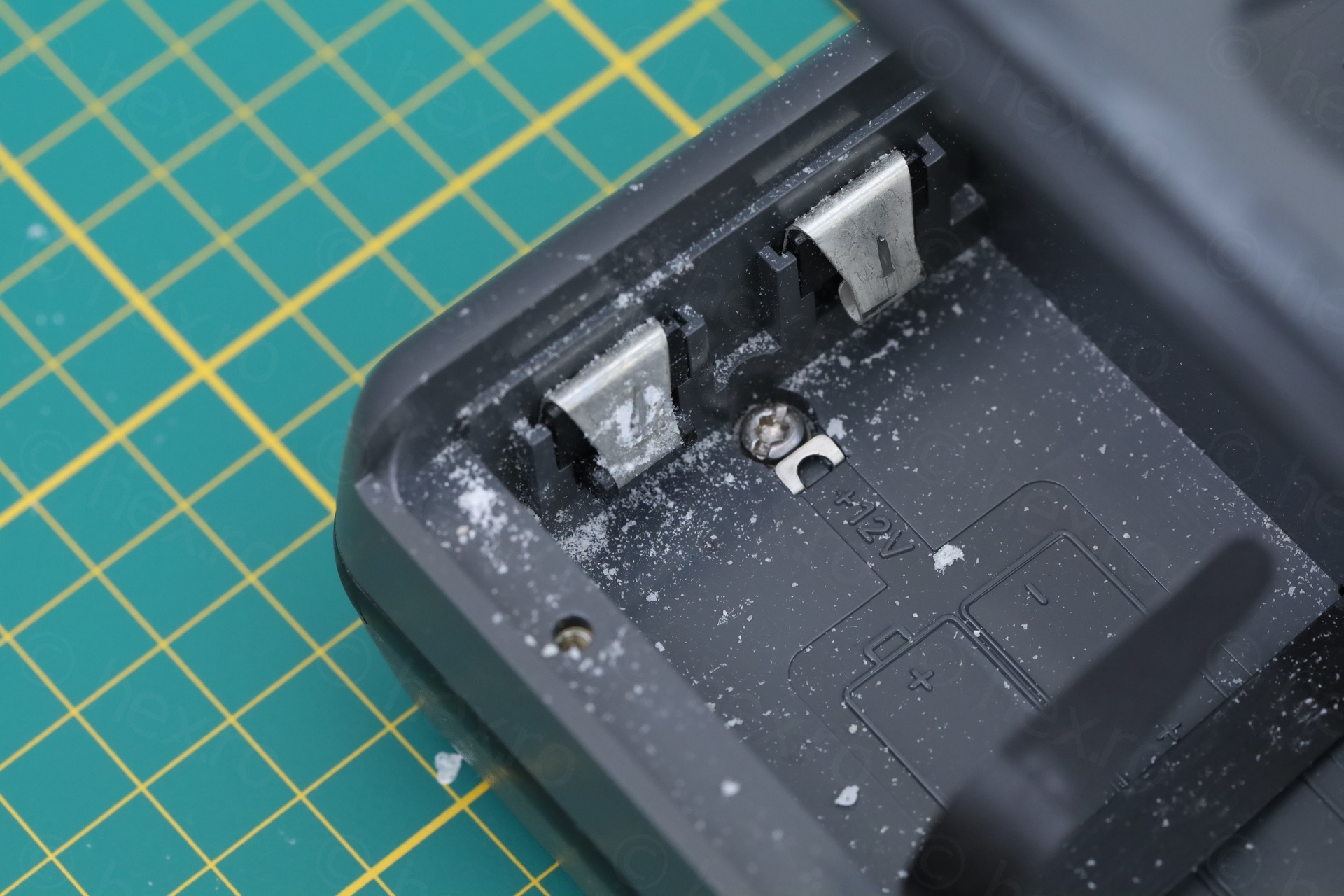
I did my best to clean the flakes using a paint brush while holding the meter up side down. More importantly, without the battery connected, the oscilloscope was starting up!
What if some of the flakes have reached inside ? I had to have a look…
Replacing dead capacitors
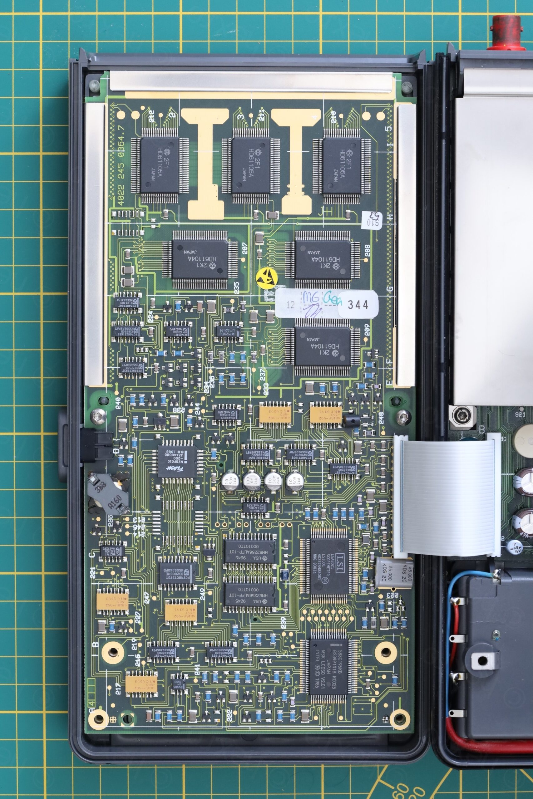
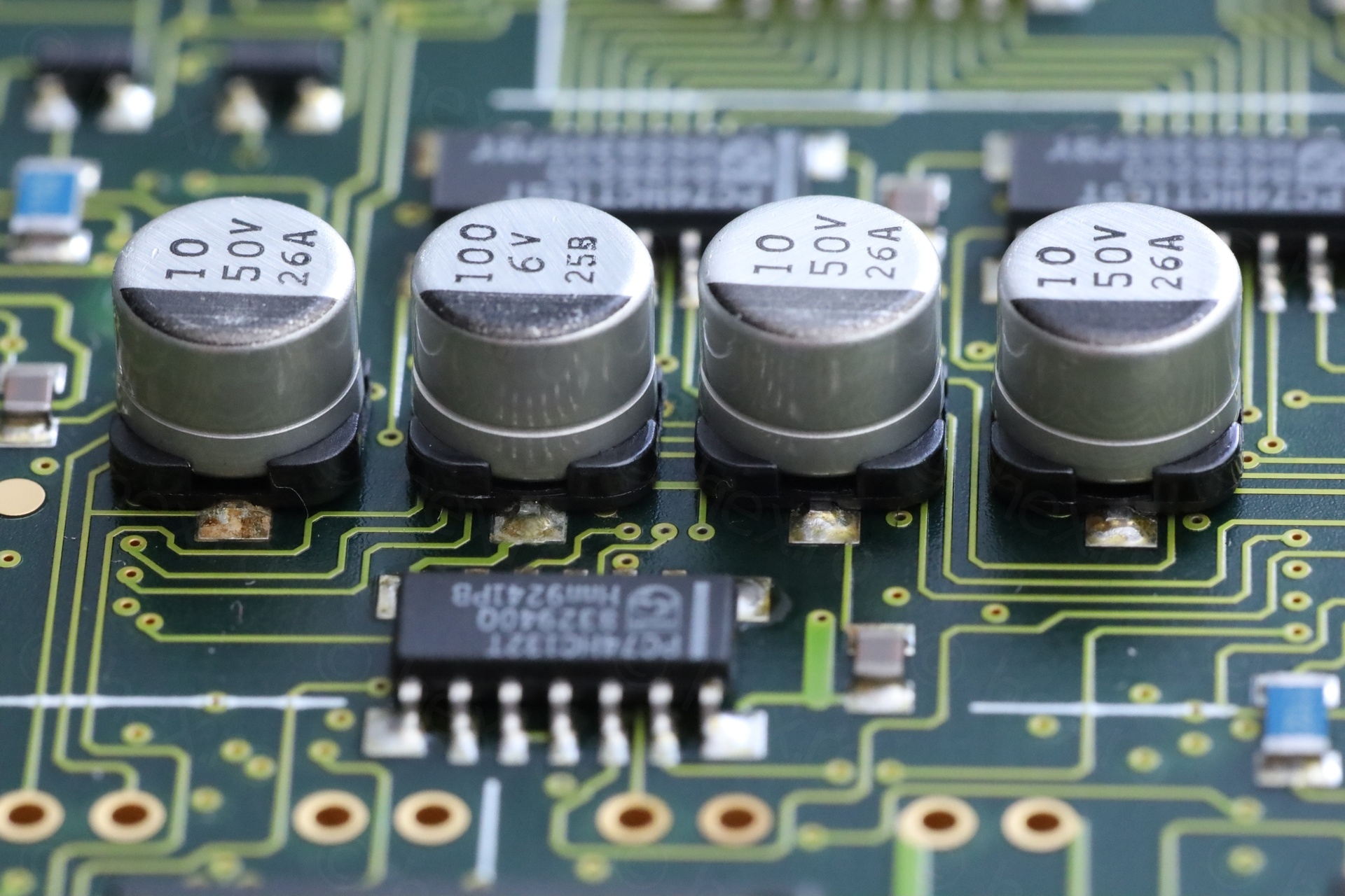
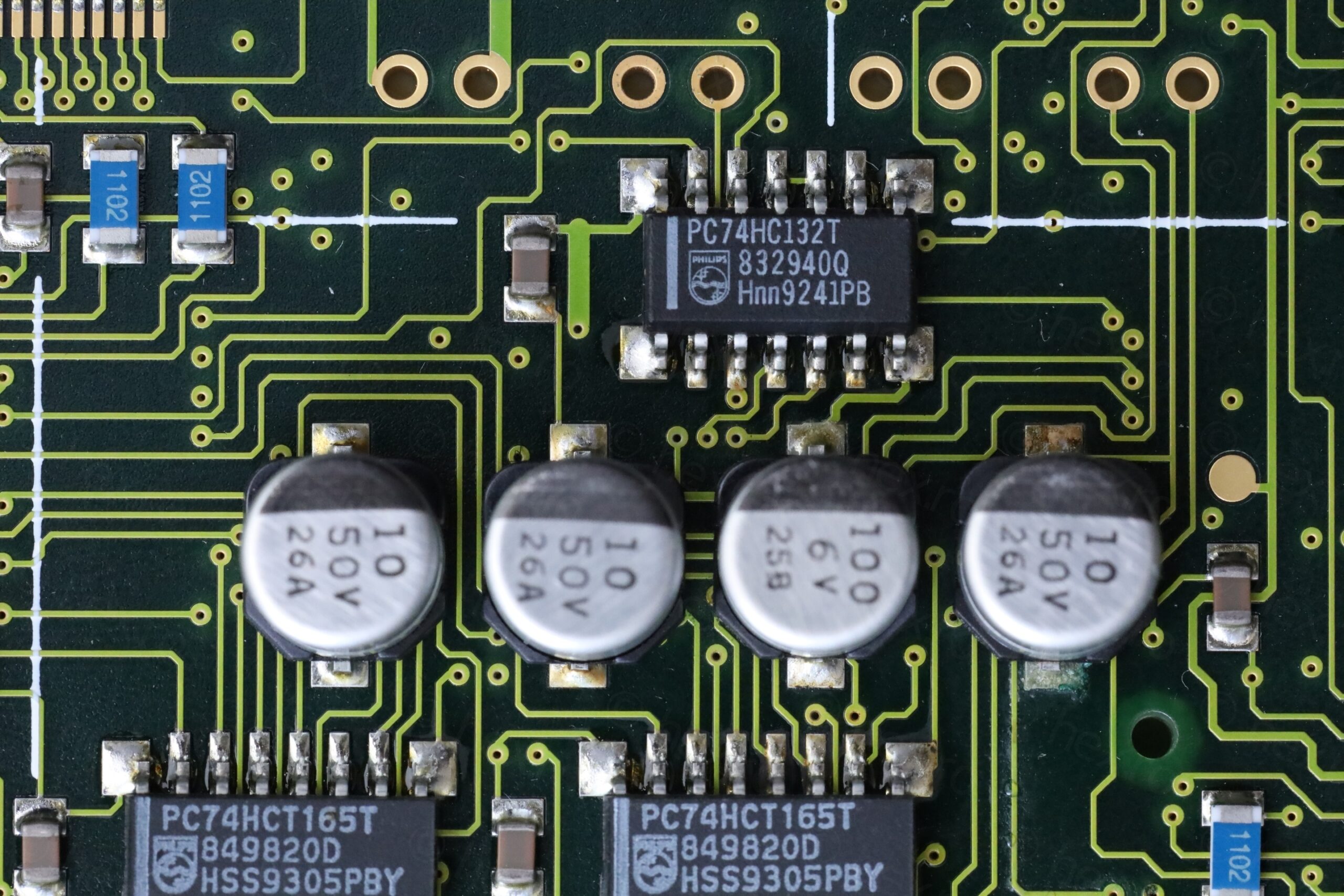
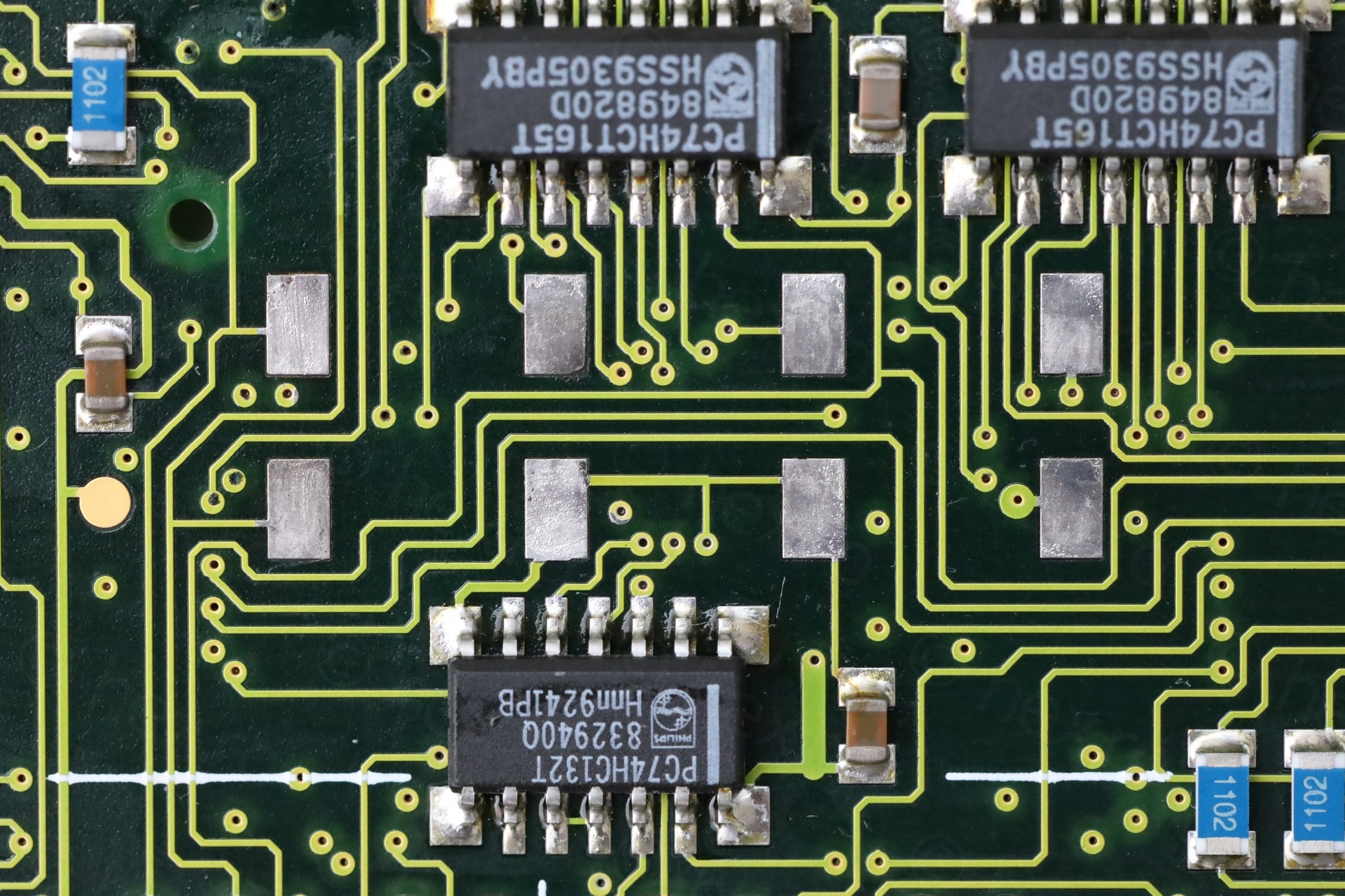
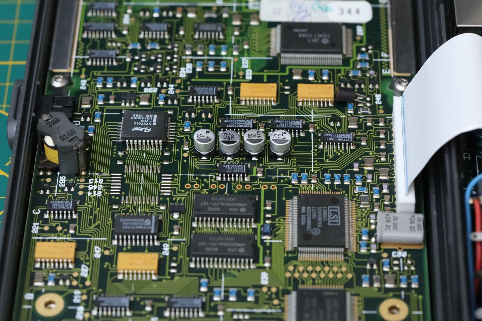
As a testament to Philips build quality, no flakes have reached the insides. It was squeaky clean and looked as it was never opened:
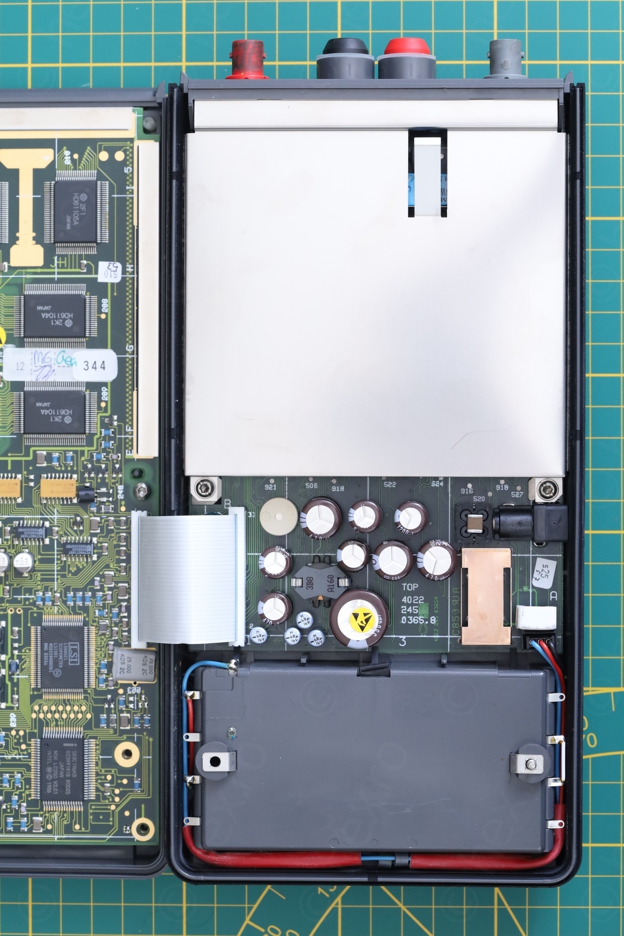
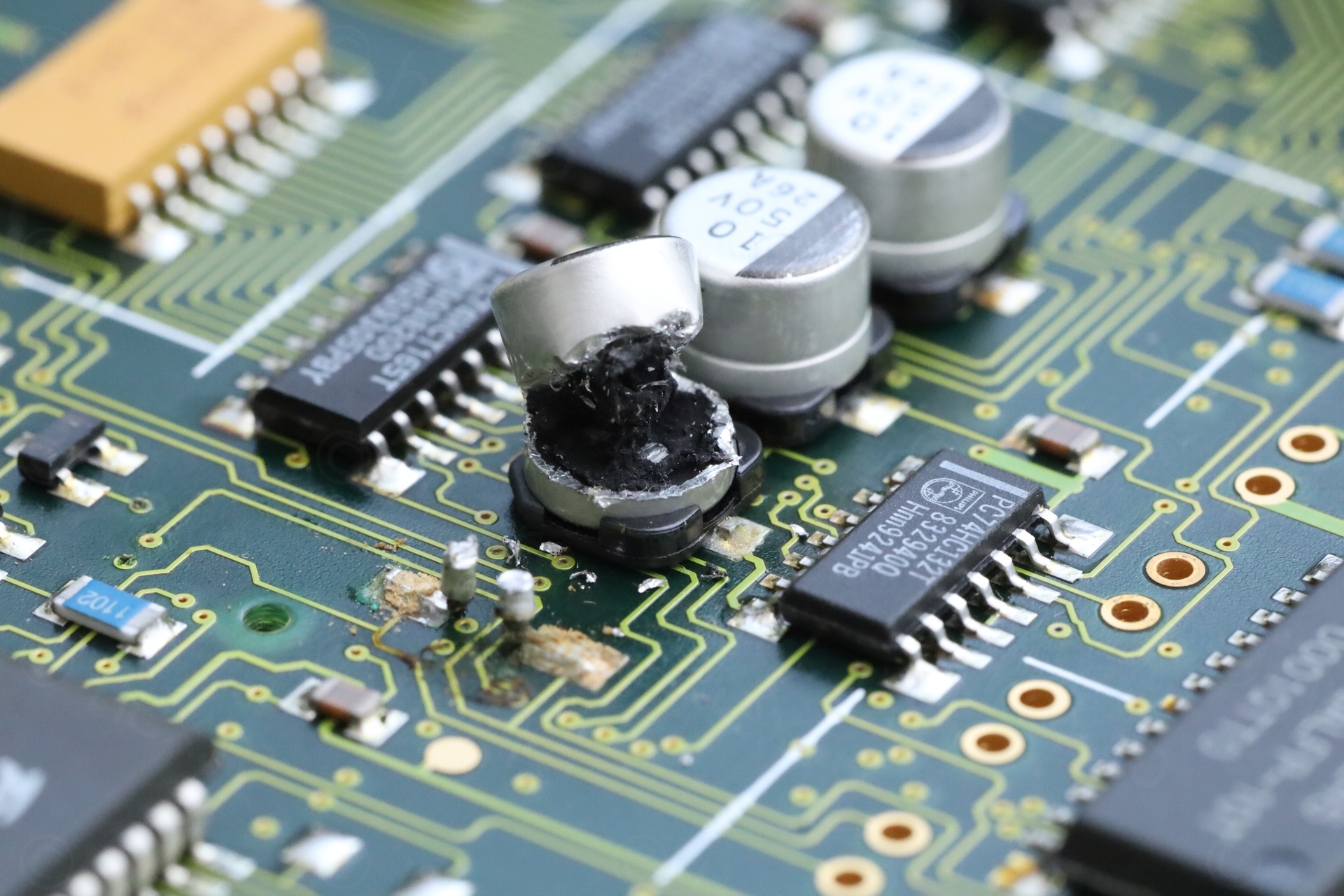
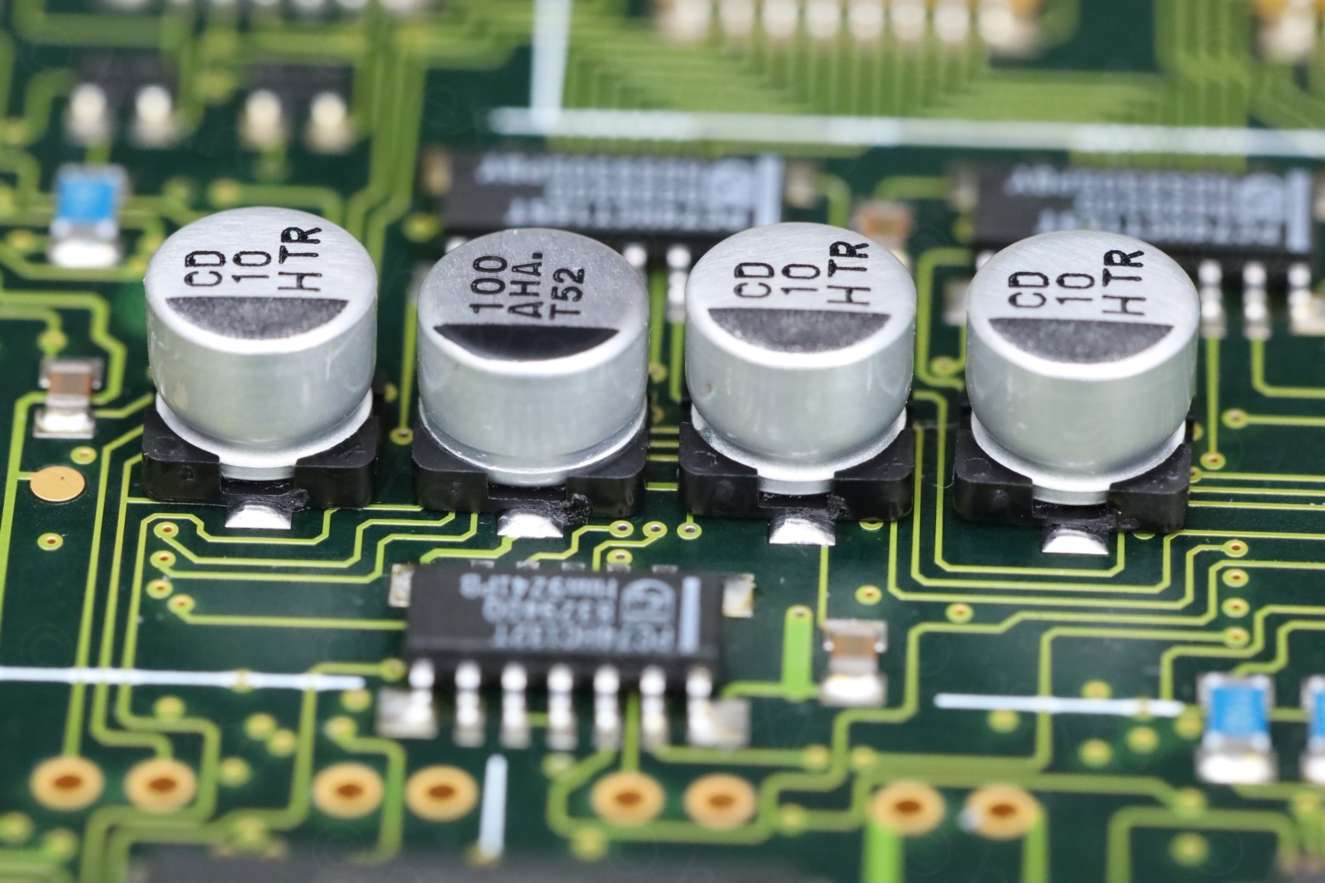
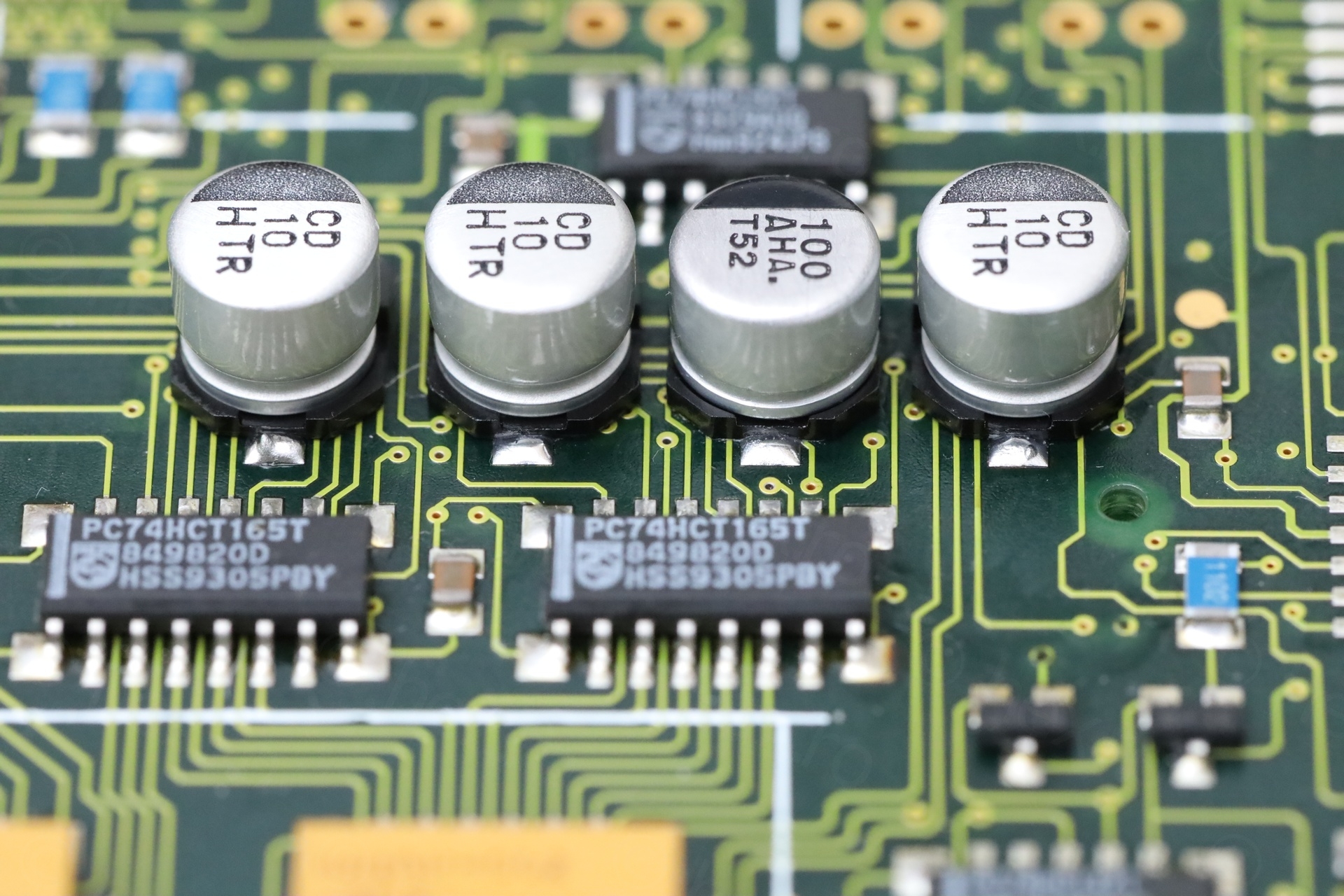
I proceeded to check the 4 known to leak capacitors. They were leaky..
To remove them, I used some side cutters to nibble away at the cans and get access to each individual leg. Maybe I am wrong, but it feels the safest way to remove the capacitors, as long as you don’t try to cut large chunks of them. Otherwise, too much mechanical stress on the pads:
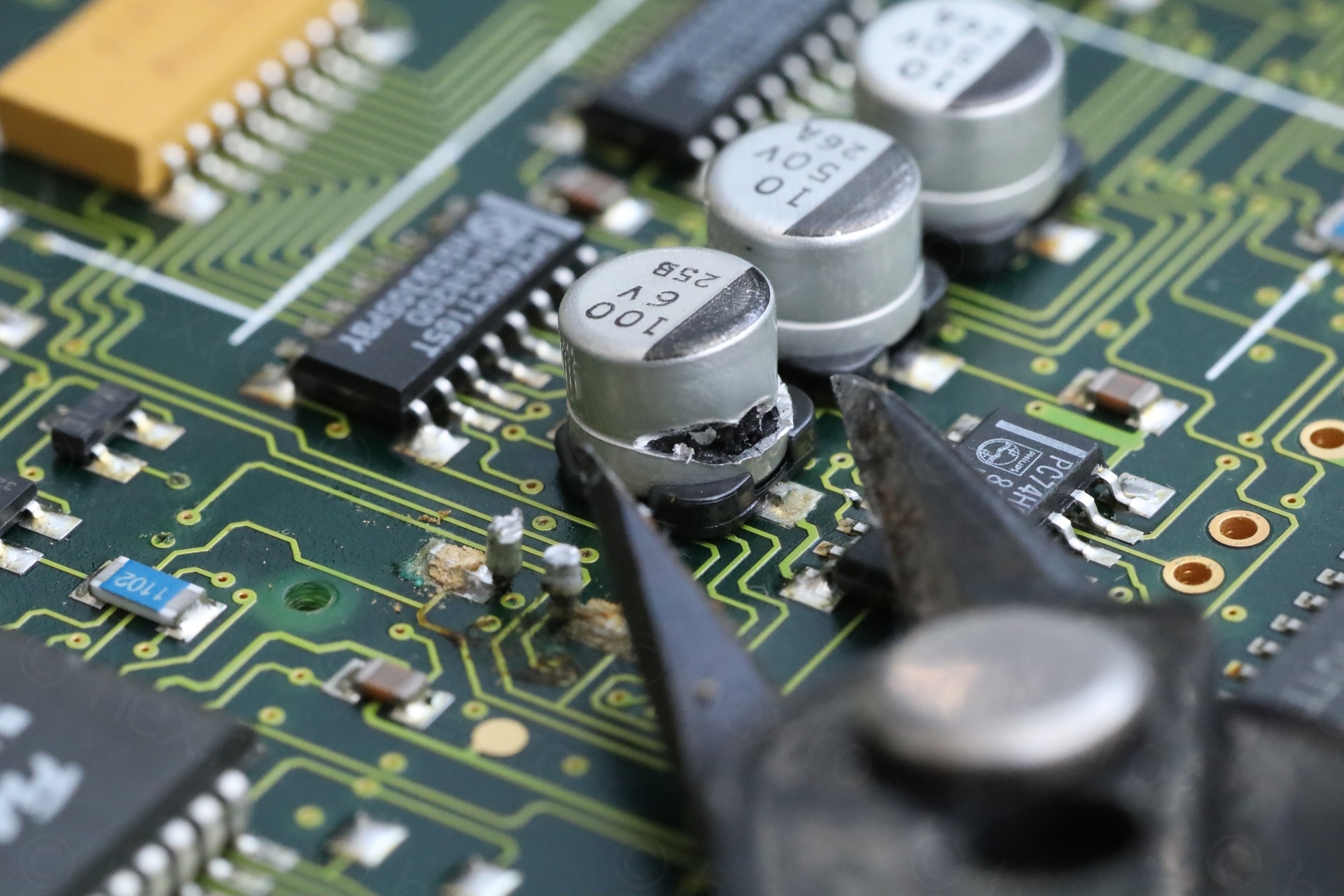
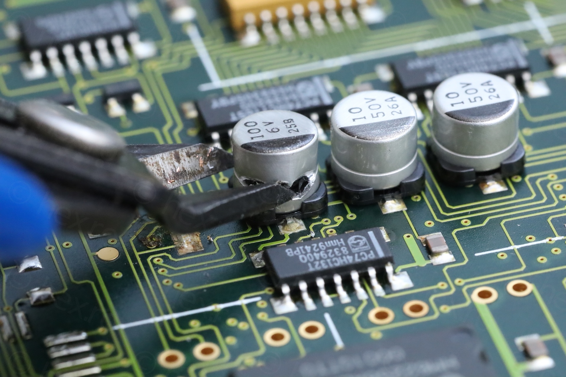
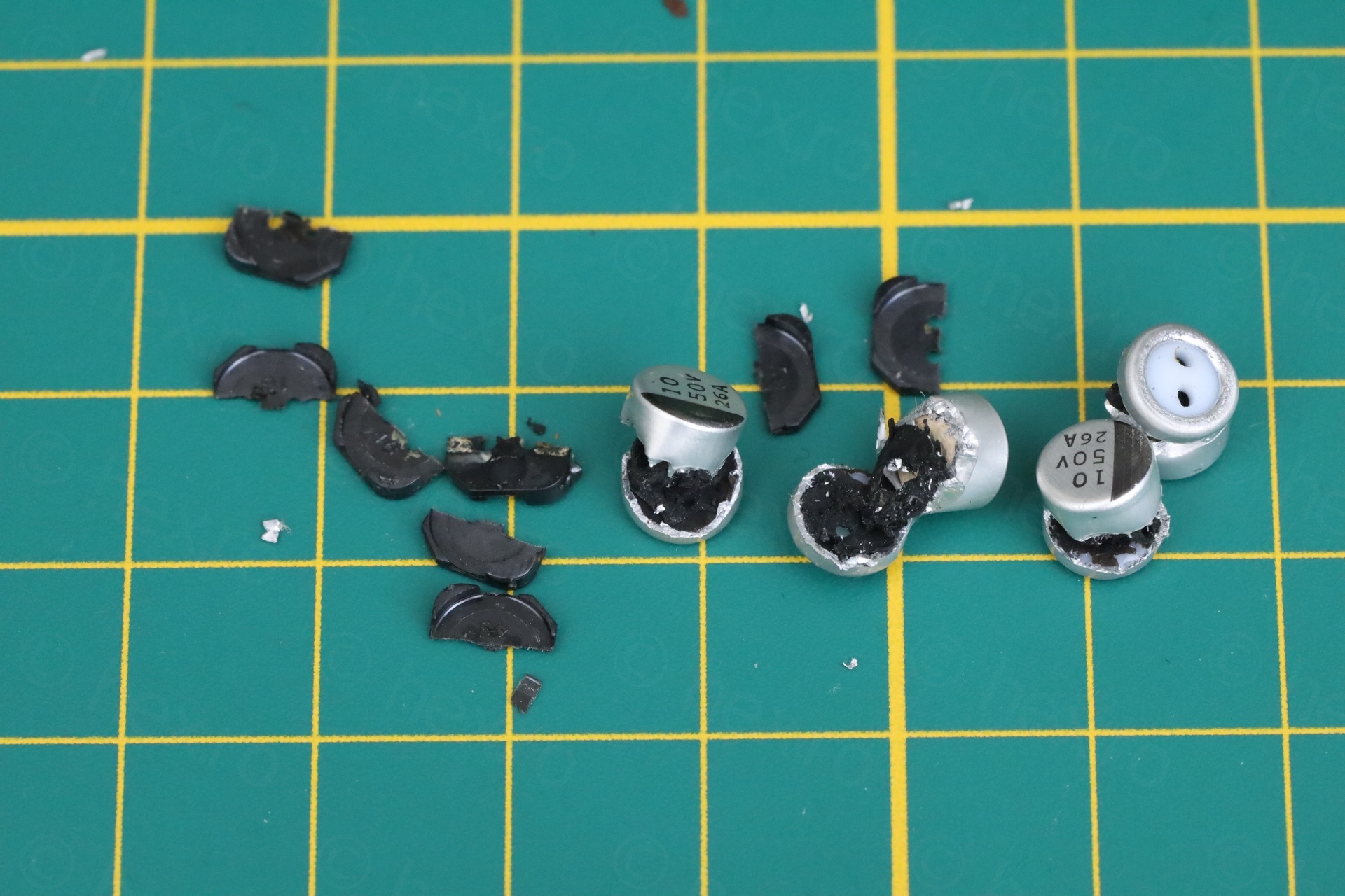
I got to them in time, corrosion just started:
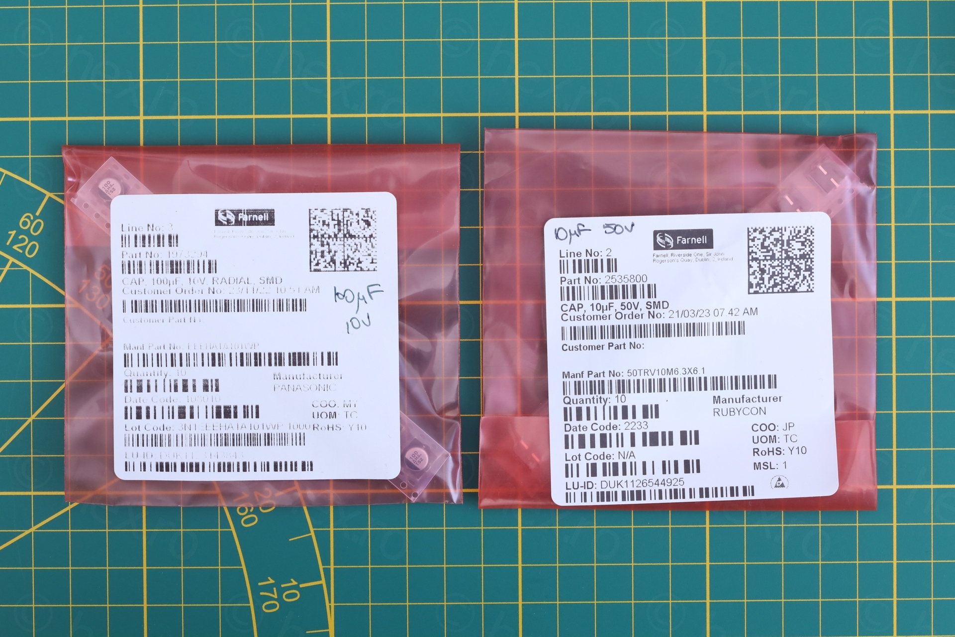
After removing each leg, there were still some dark stains on the pads and the stains weren’t coming off just with cleaning with IsoPropyl alcohol. But adding a bit more flux + solder, then cleaning with solder braid was helping. I managed to get them as clean as I could and proceeded to solder fresh new capacitors:
Thinking I did a good job, I focused on cleaning the grime from the case of the oscilloscope and put it back together:
Some buttons don’t work
But then I discovered that KEY_3 (middle top soft button), the cursor buttons (cursor l1 and cursor 2) as well as Cursor Data buttons did not work!
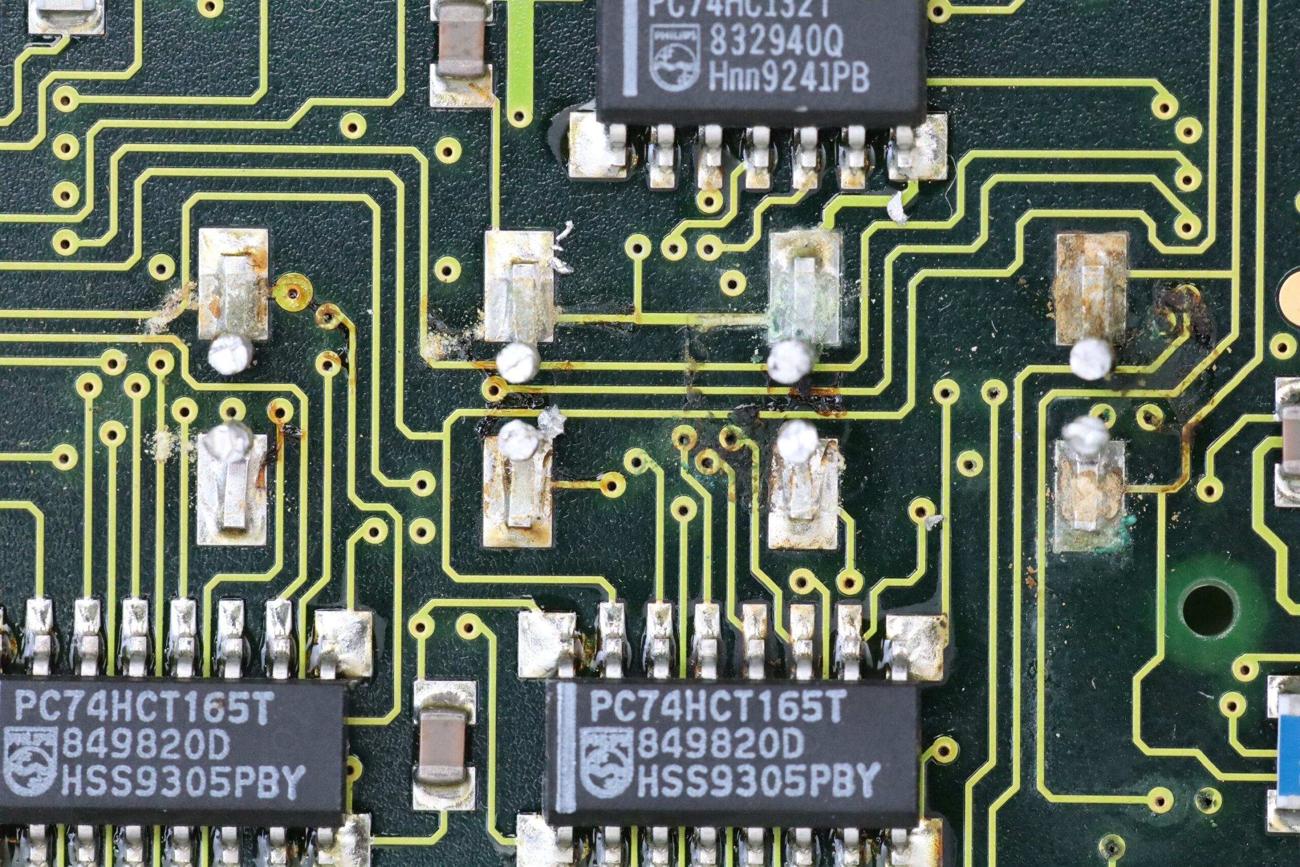
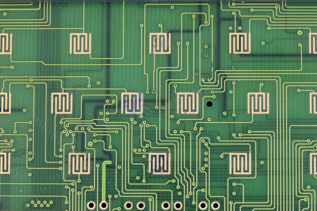
I had to take it apart again, and found a mess of corrosion on the keyboard membrane as well as on the circuit board:
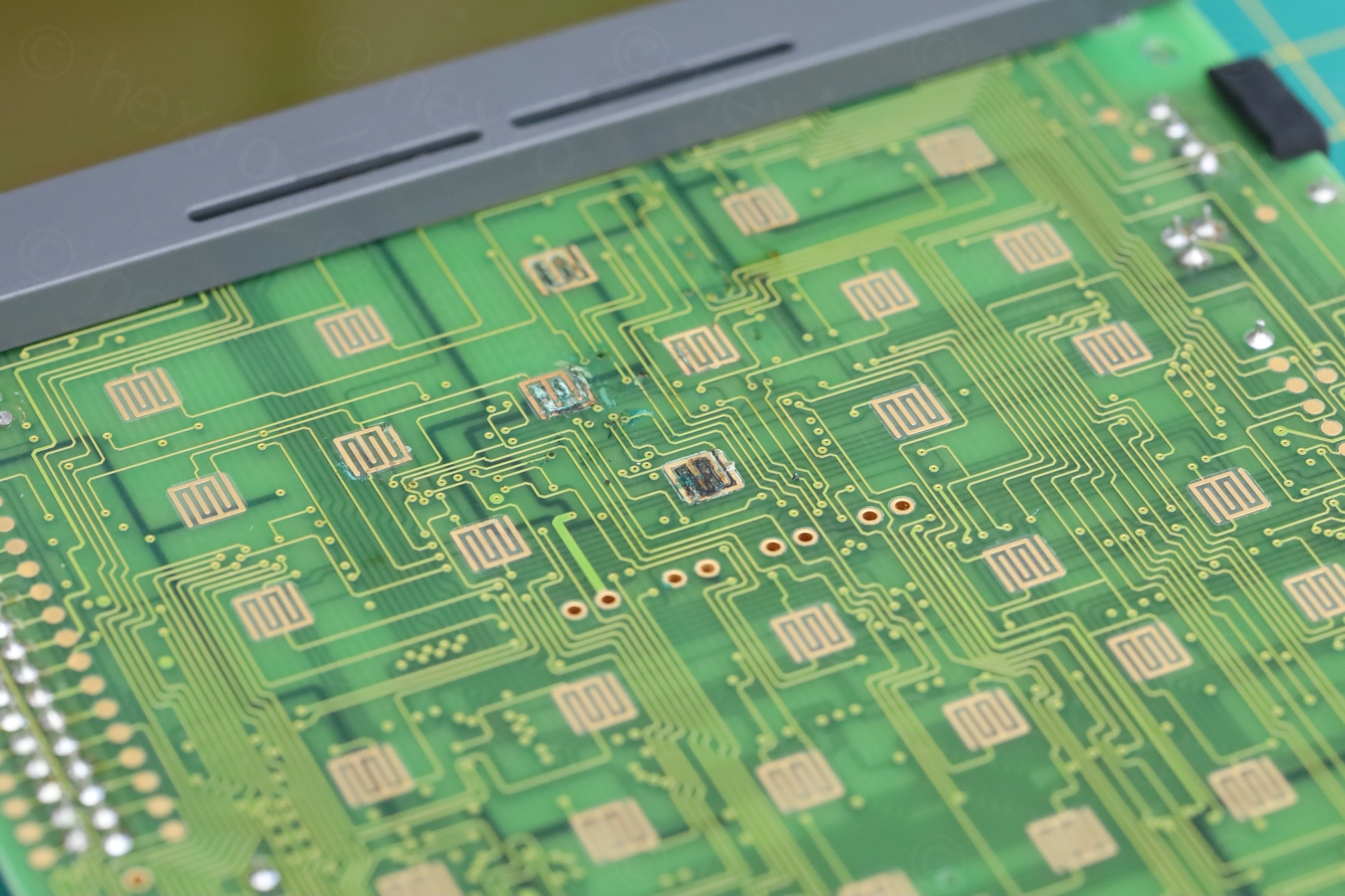
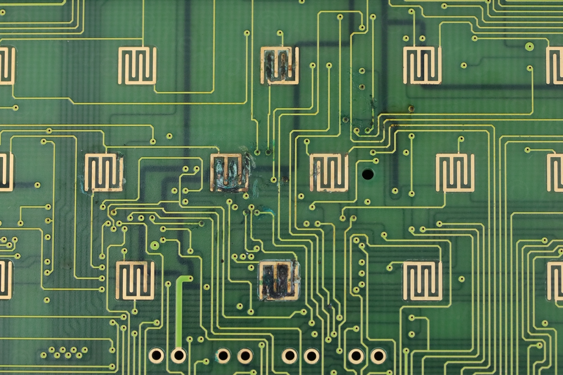
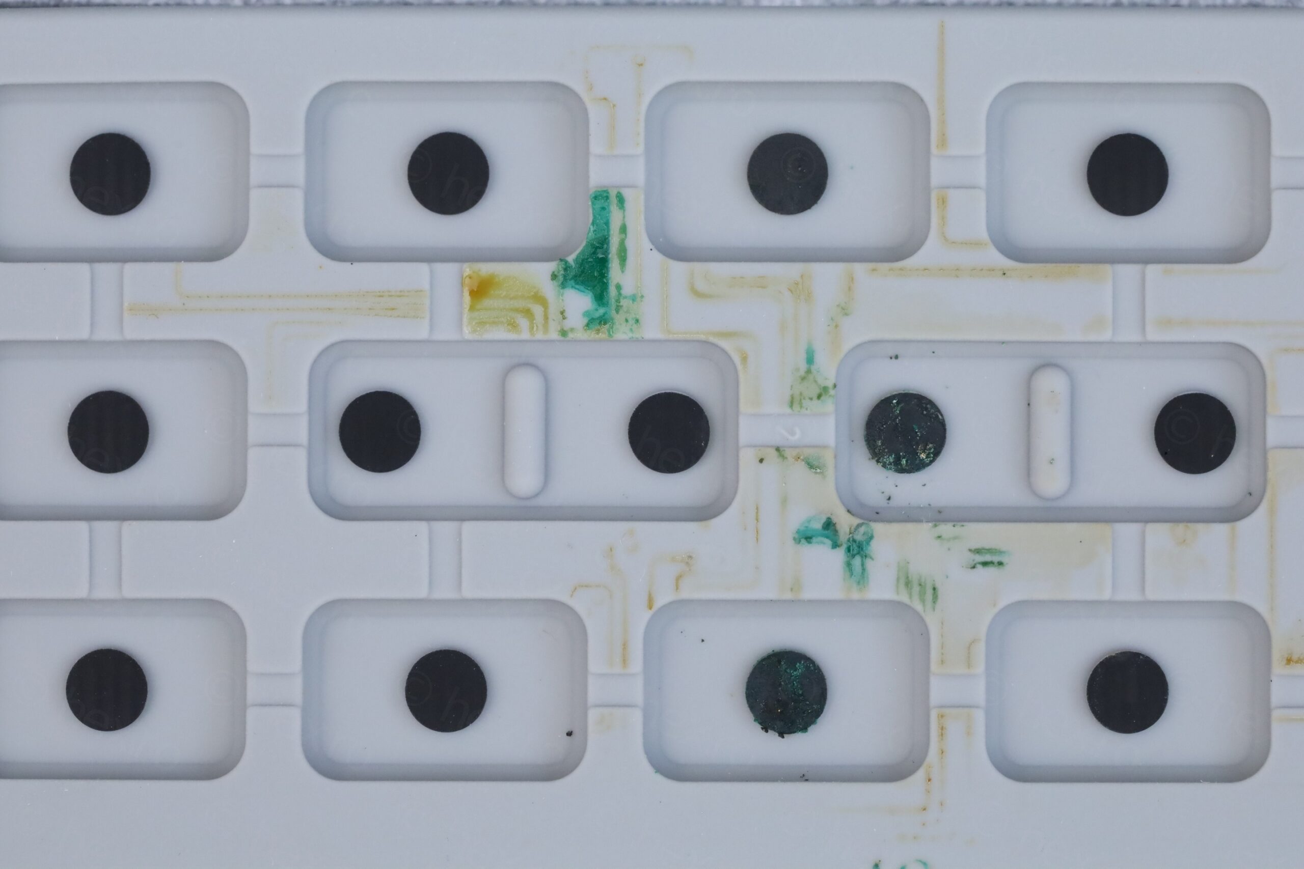
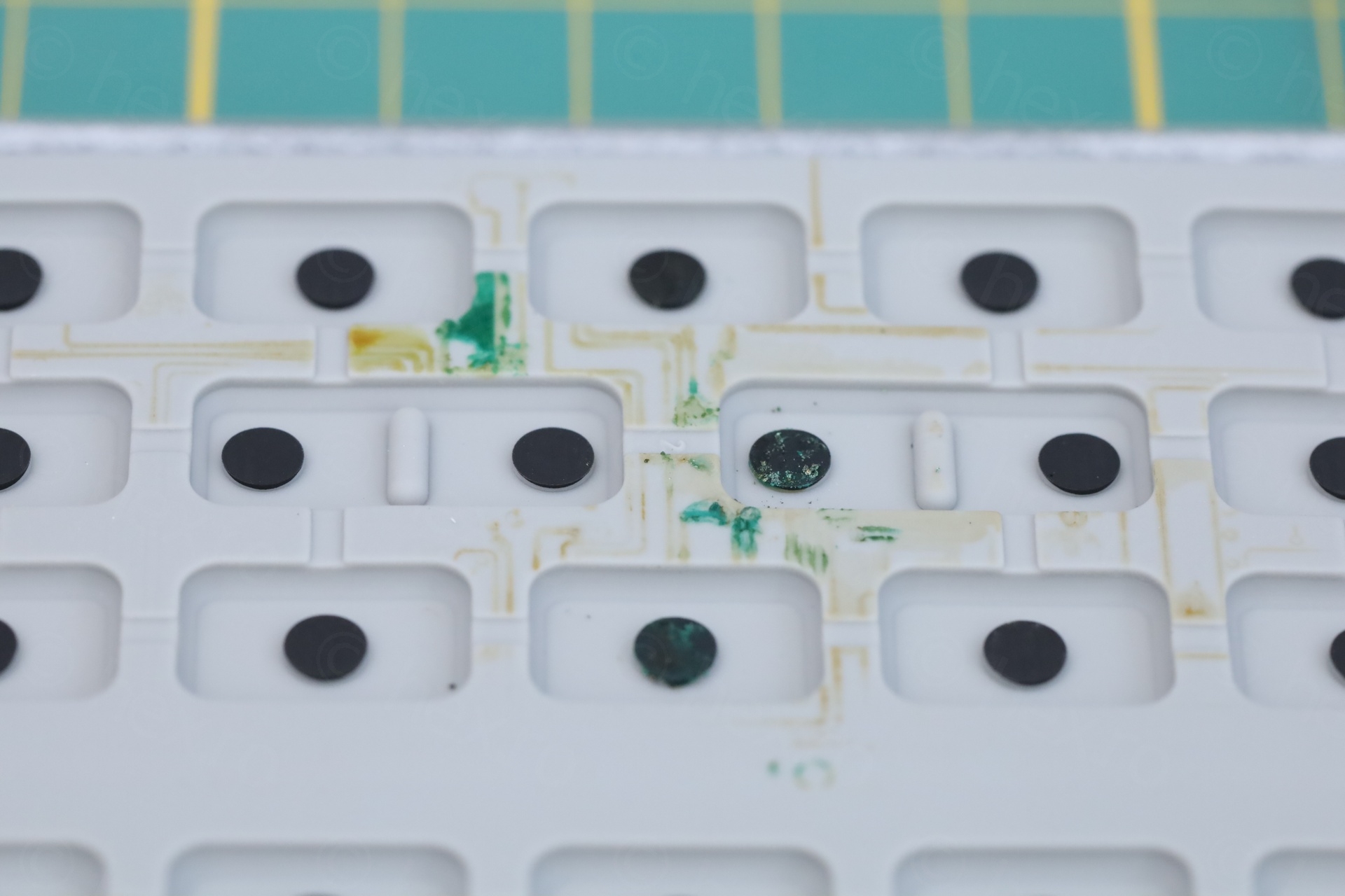
Kept wondering how it got there, since there was no sign coming from outside (the rubber membrane was spotless on the top). Until I realized those buttons sit behind the 4 leaky capacitors!
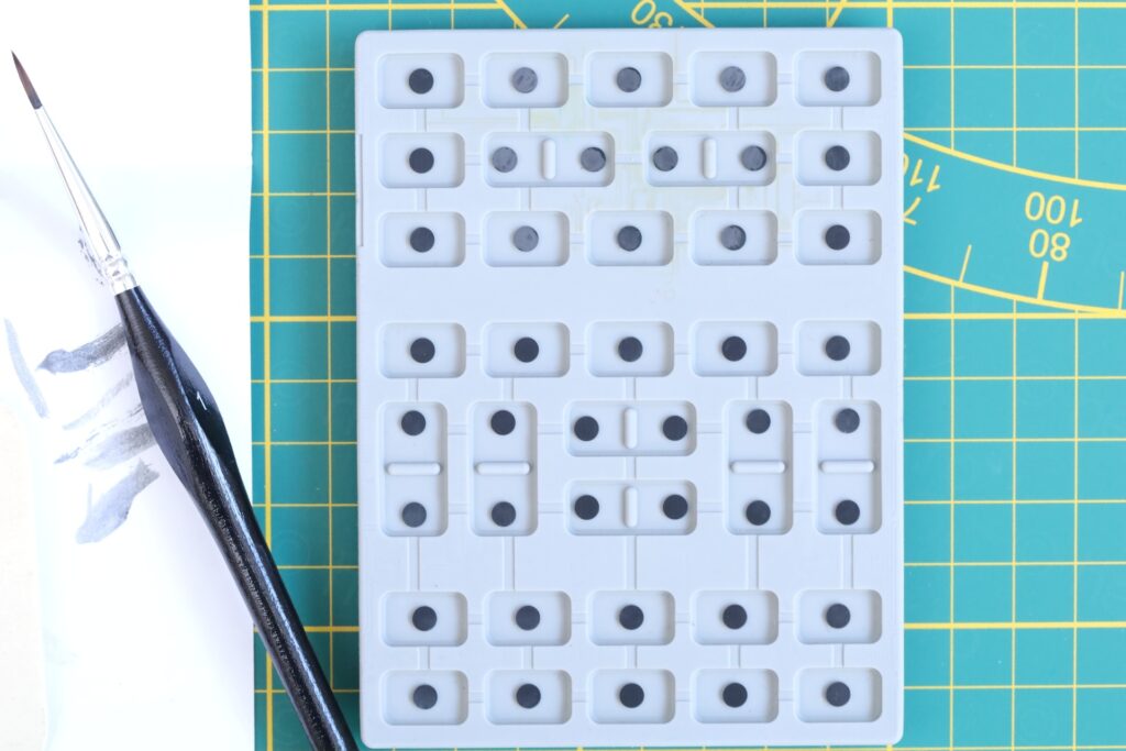
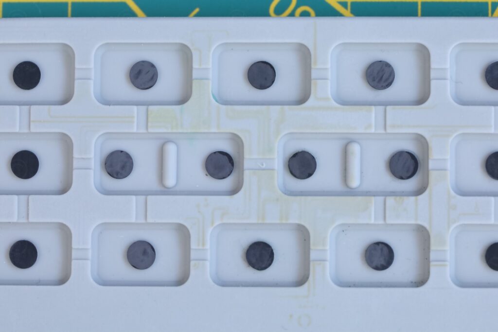
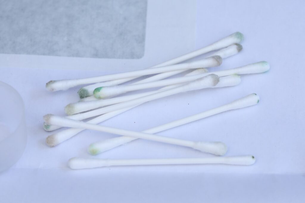
I cleaned the circuit board corrosion with LOTs of scrubbing using IPA. The rubber Keyboard membrane got almost the same treatment, except I never touched the graphite pads themselves:
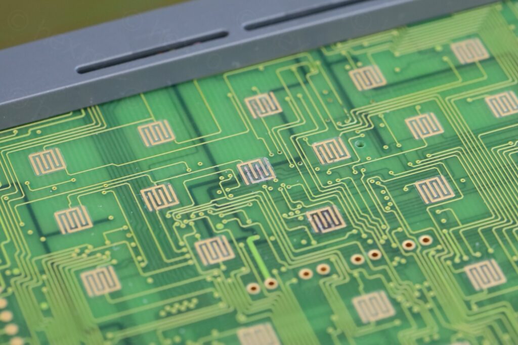
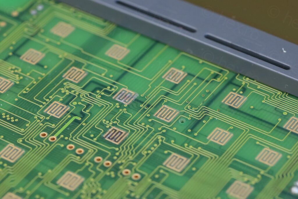
To see if the circuit board cleanup worked, I had to test with a working button …
… but the Cursor Data button itself was not triggering the contact. Its graphite pad was affected by the corrosion. I decided to load it up with Graphite and this fixed it. I had some gloves to not leave fingerprints over the screen / metal cans ..
By now I became attached to the poor surviving oscilloscope. Its backlight was working fine, no need to have it replaced. It was just missing the power supply.
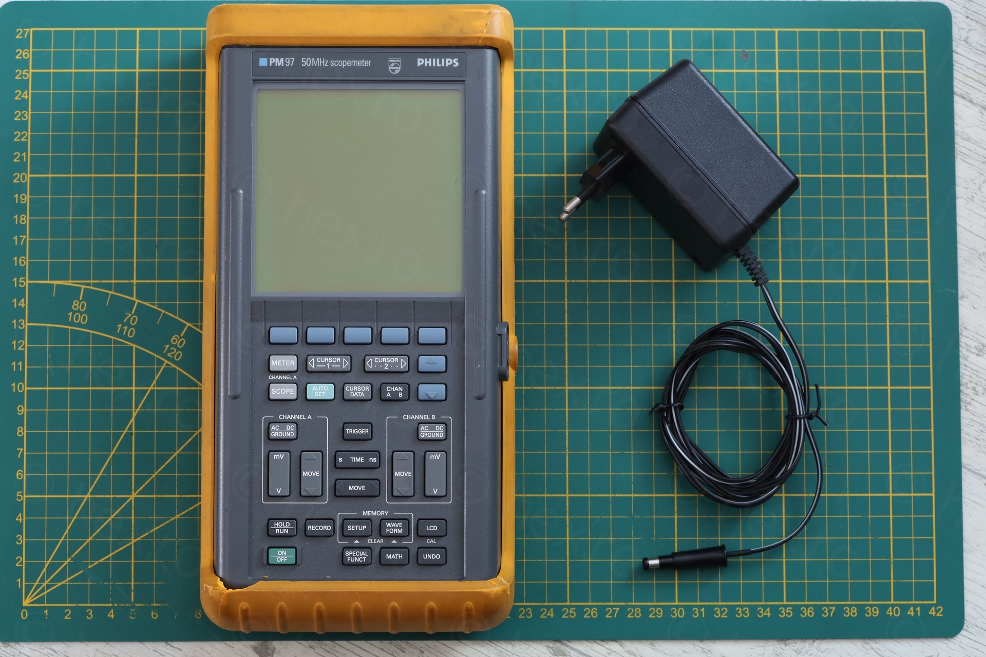
DIY Power Supply
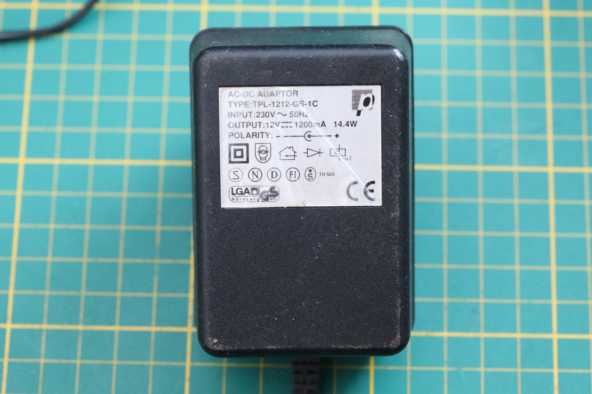
The price of an original power supply kept me away from buying one. After reading an interesting post on eevblog forum from member carl_lab – it became clear what is needed. The transformer needs to be double insulated linear power supply, with a DIN45323 connector.
There are many 12V linear power supplies at the flea market. Easy to spot too, as they are bulky and heavy, but not many double insulated ones with screws. I wanted one with screws so that I can get access to the capacitor inside and replace it. One thing to note is the polarity – the Philips 97PM needs center negative, so I’ll have to pay attention when wiring it.
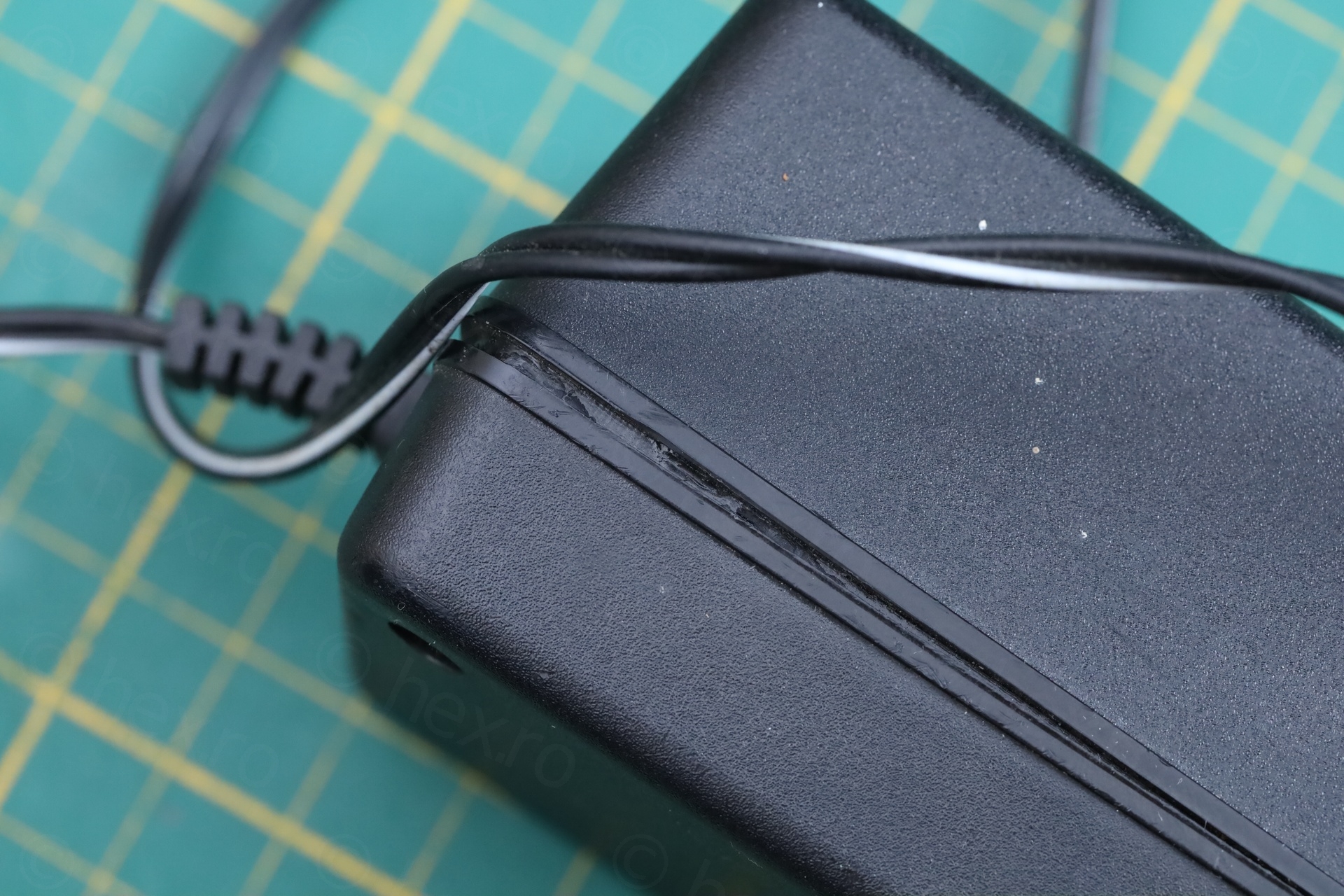
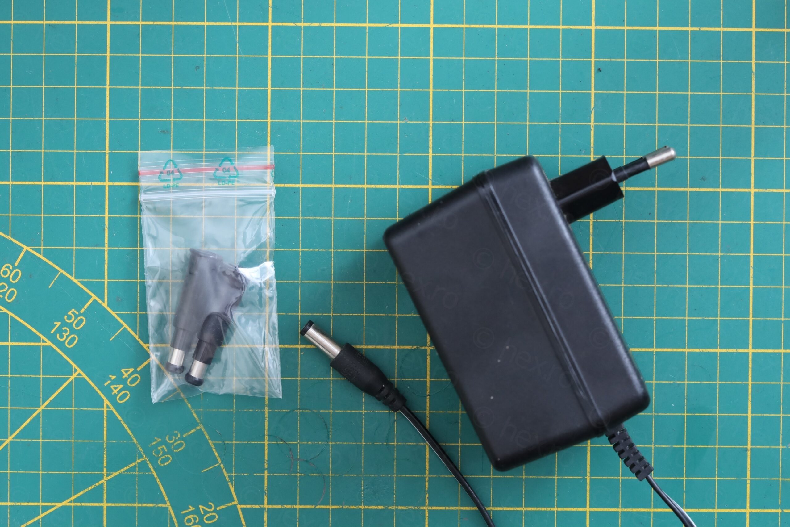
The original one is rated ~ 5W and as luck would have it, I stumbled upon an acceptable replacement. Its case was splitting apart (but still had the two screws) and is both double insulated (the square within a square symbol is shown on label, as otherwise, I can’t judge if it is – no expertise in these standards) and rated for 14W:
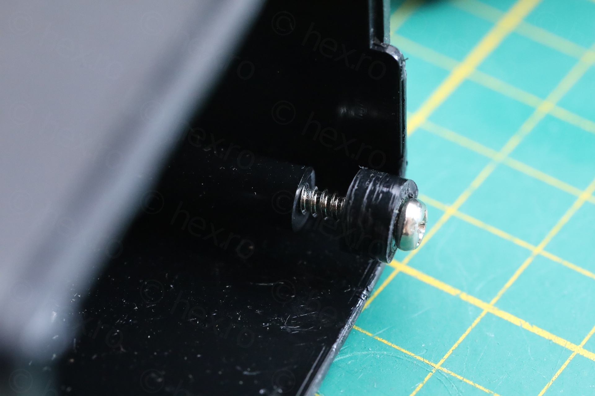
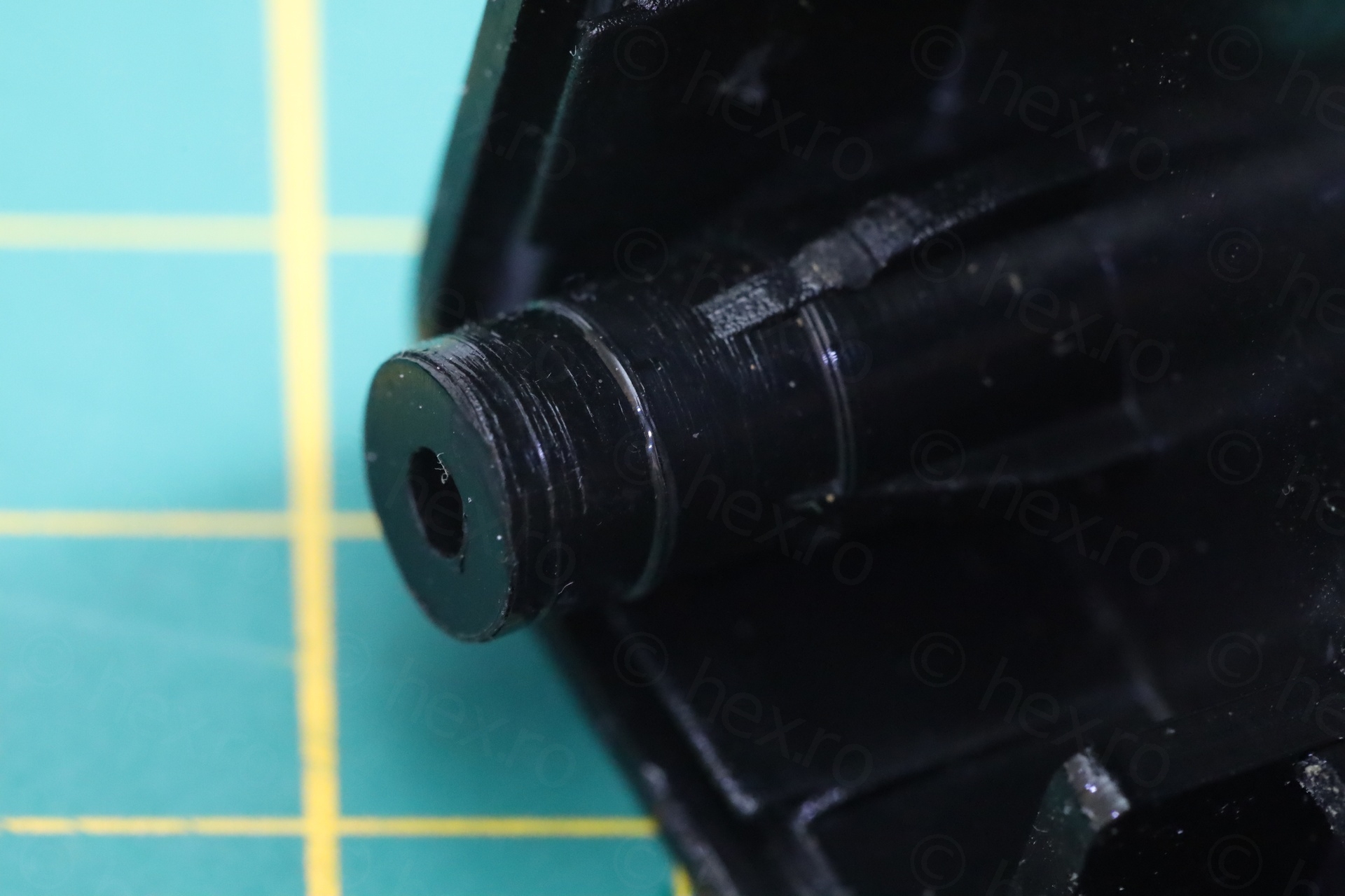
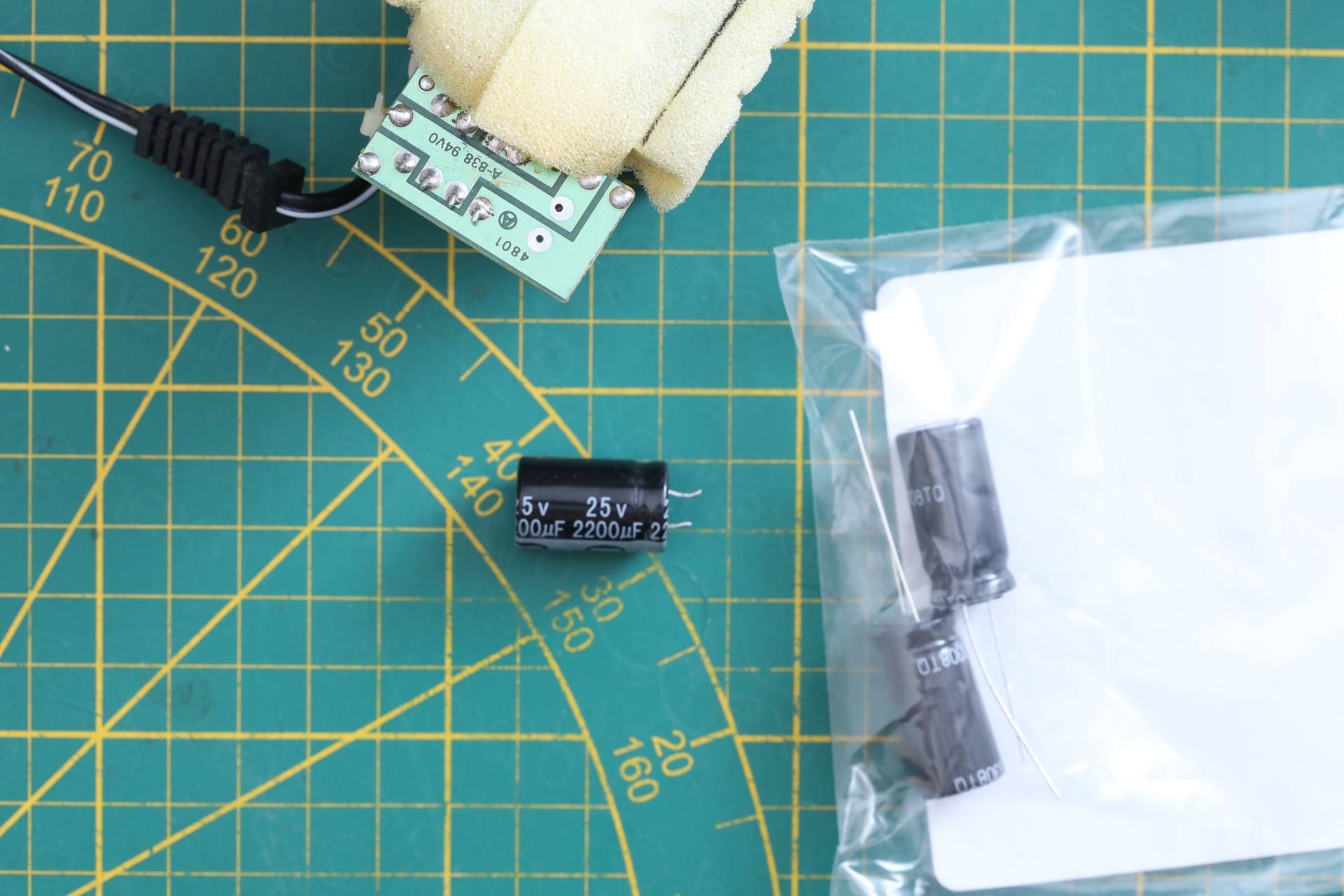
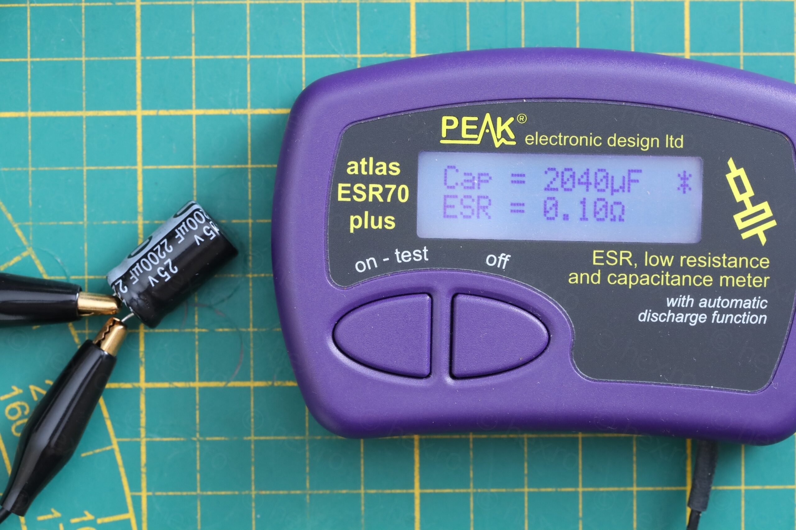
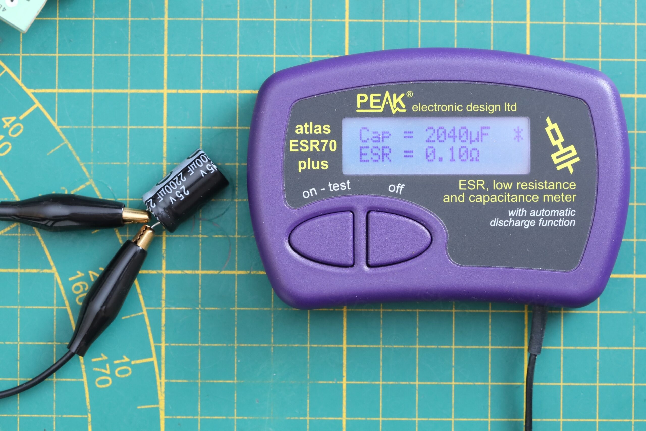
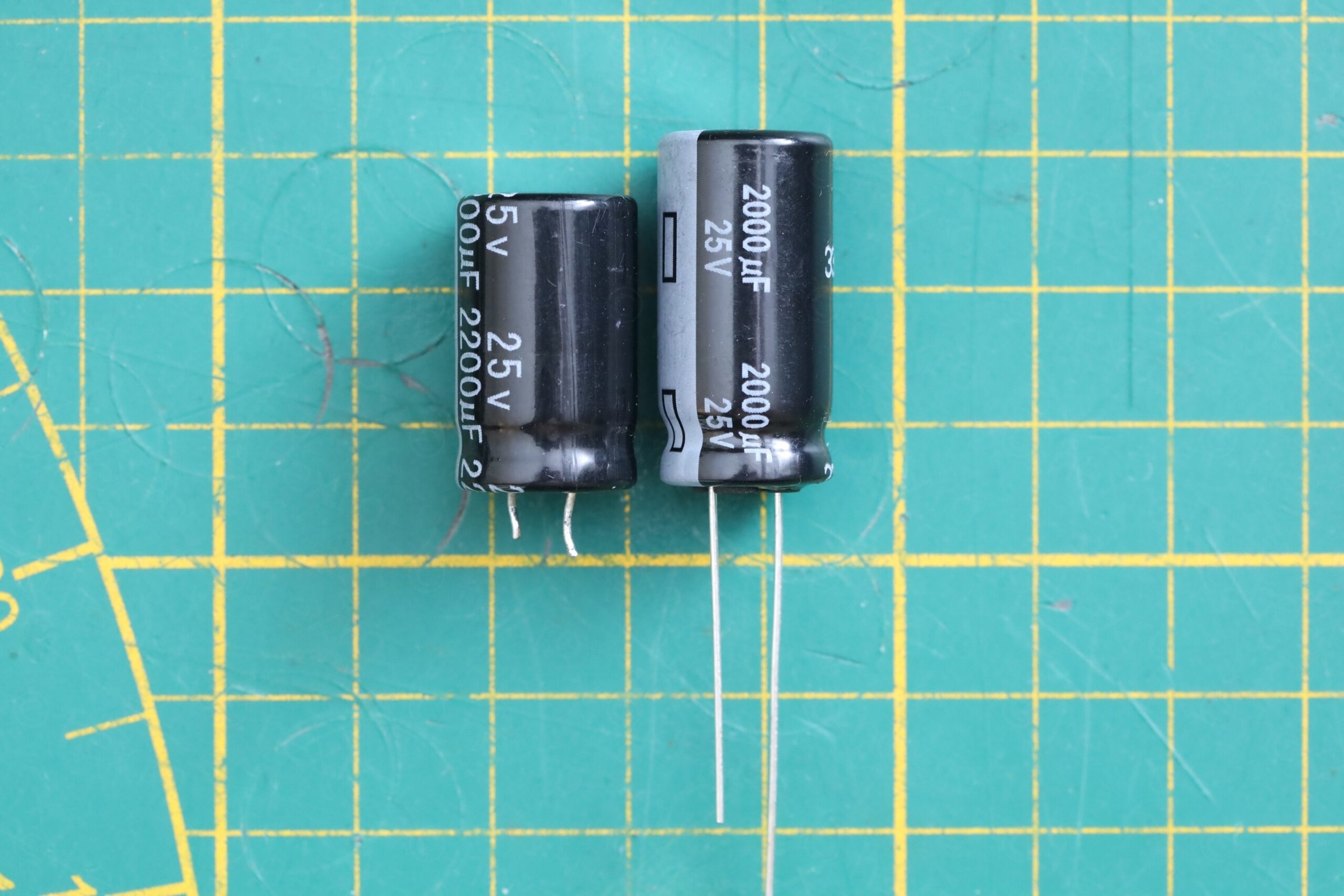
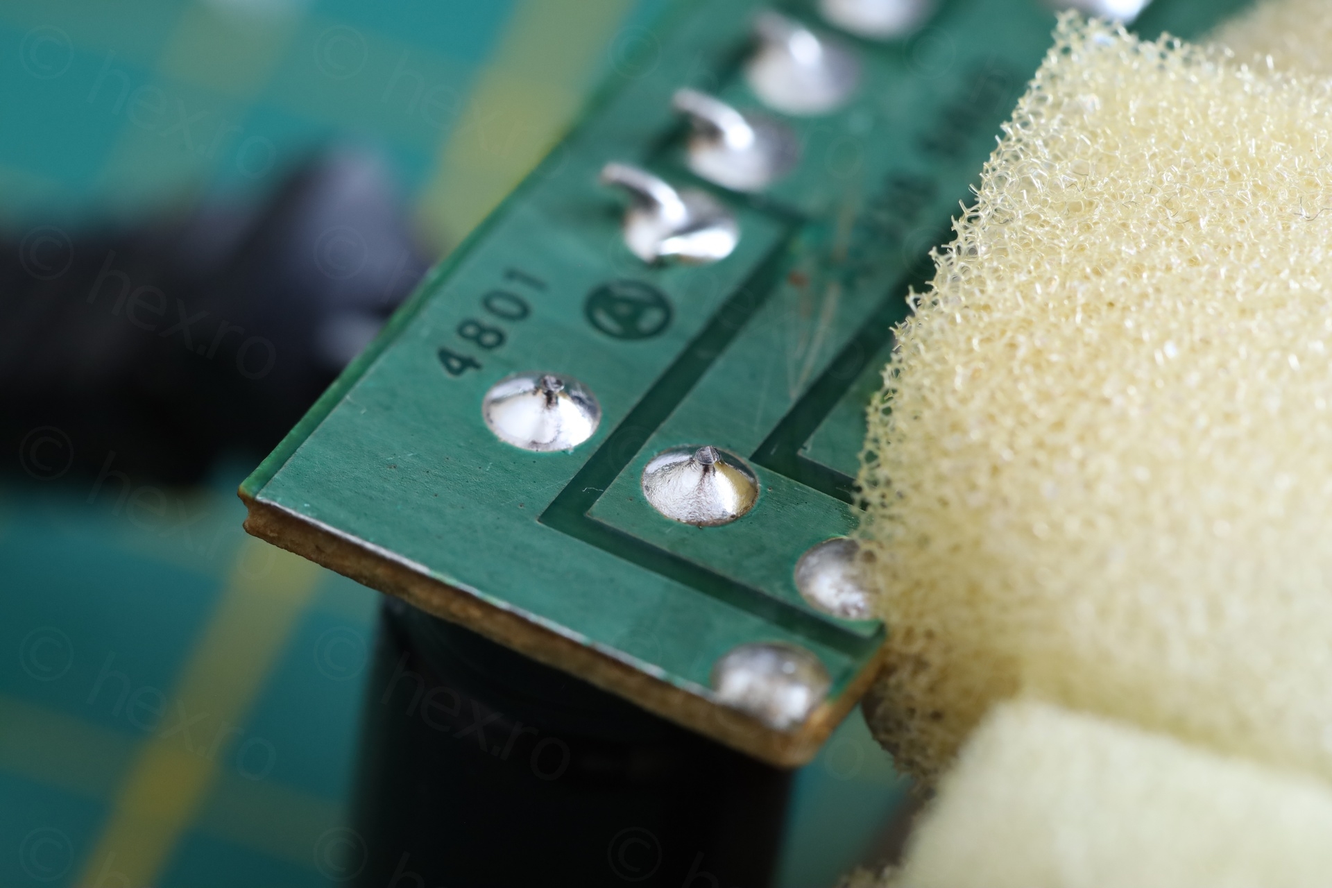
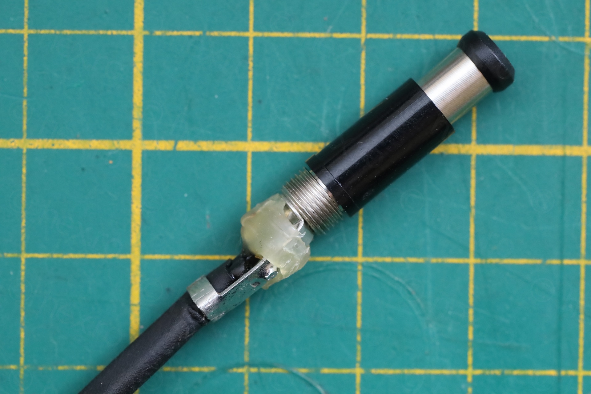
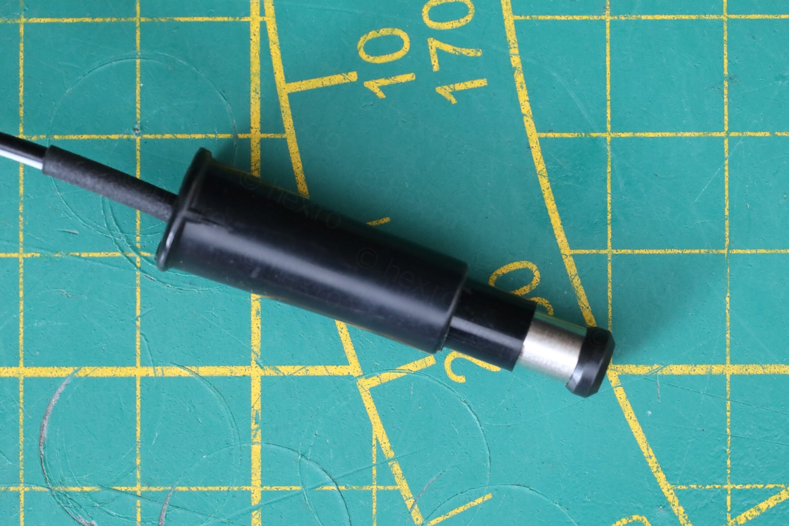
I have epoxied the cracked screw post, swapped the capacitor (even if it was not needed, according to the ESR meter) and adapted the new connector (after triple checking that the polarity is right for the oscilloscope).
Although the voltages do not match (original is 15V I believe, this one is 12V), the Philips PM97 is rather tolerant input voltages, and 12V works fine too.
Testing
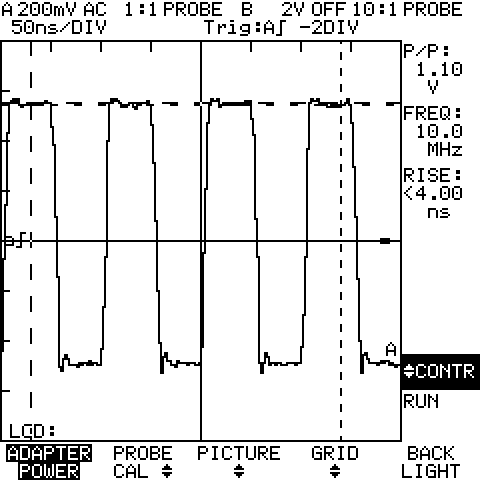
Auto-ranging on 5V Square signal
In my previous blog post about a Fluke 97 oscilloscope, I received a comment related to auto-ranging issue on a 5V signal. So I figured I’d test this behavior.
The signal generator was set to 1Mhz, 5Vpp and 50Ω Load. Signal passes through a P57 50Ω Feed through connector to the oscilloscope. This one seems to auto-range fine and identifies the signal as 5Vpp and 1Mhz frequency:
Bandwidth estimation
For bandwidth estimation, I used Leo Bodnar’s LBE-1321 Fast Risetime pulser – connected through the same P57 50Ω feed through connector:
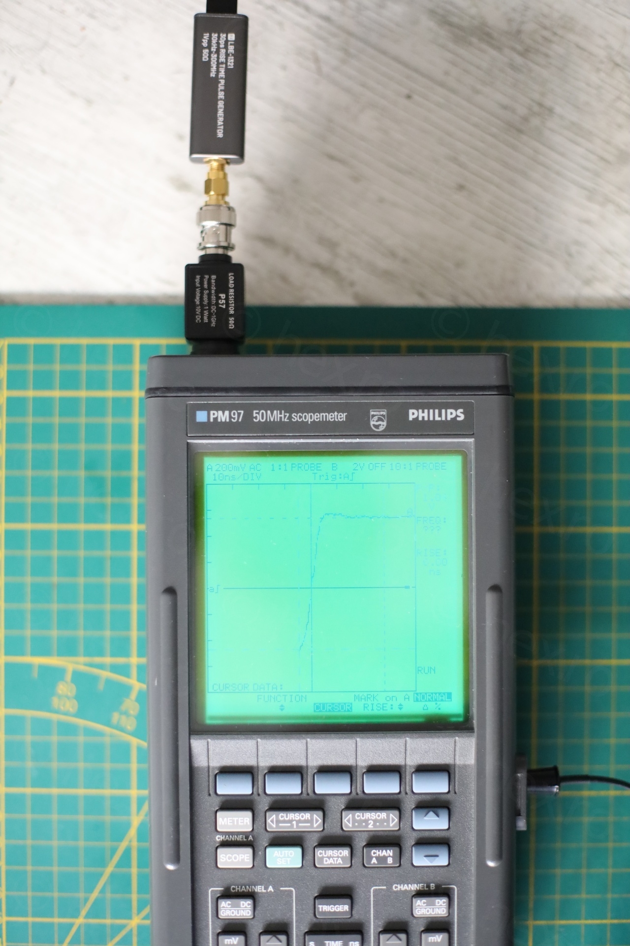
I configured the scope to display the signal rise time, but each time, the small cursors wiggle a bit and measurements changes. Most of the time it calculates the rise time to be around 5.6ns, but I saw extremes as 5.2ns or 6.4ns:
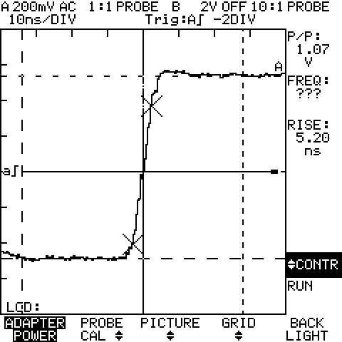
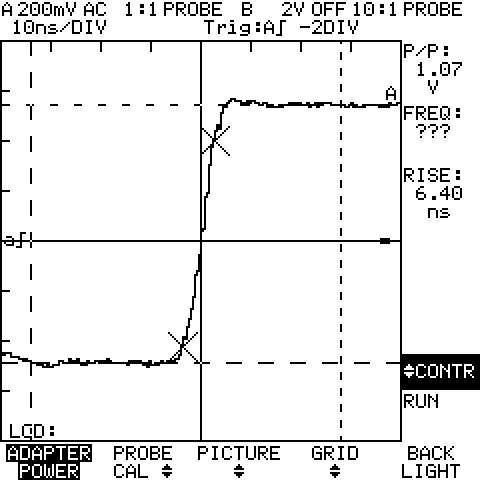
Using the formula that BW ~= 0.35 / Risetime, and using the worst case measurement of 6.4ns that I saw, this equates to BW ~= 54.7 MHz, for a 50Mhz rated oscilloscope. It is well within spec.
Conclusions
After swapping the leaky electrolytic capacitors, cleaning the corrosion and repairing the keyboard buttons, this oscilloscope is working fine. It looks nice and I’m still impressed that not only you could capture the data (for an oscilloscope released in year 1991) but transfer was via Infra Red, keeping the scope isolated. Well made.
Leave a Reply