I found this mini CRT inside a JVC GR-AX680EG camcorder that I bought at a flea market.
Camera
Camera was sold in a nice green bag – and although more cumbersome to carry back home, sometimes the bags have small hidden gems. All of a sudden, besides the camera, a little part of the life of the person is in front of you. So many questions, so little leads.
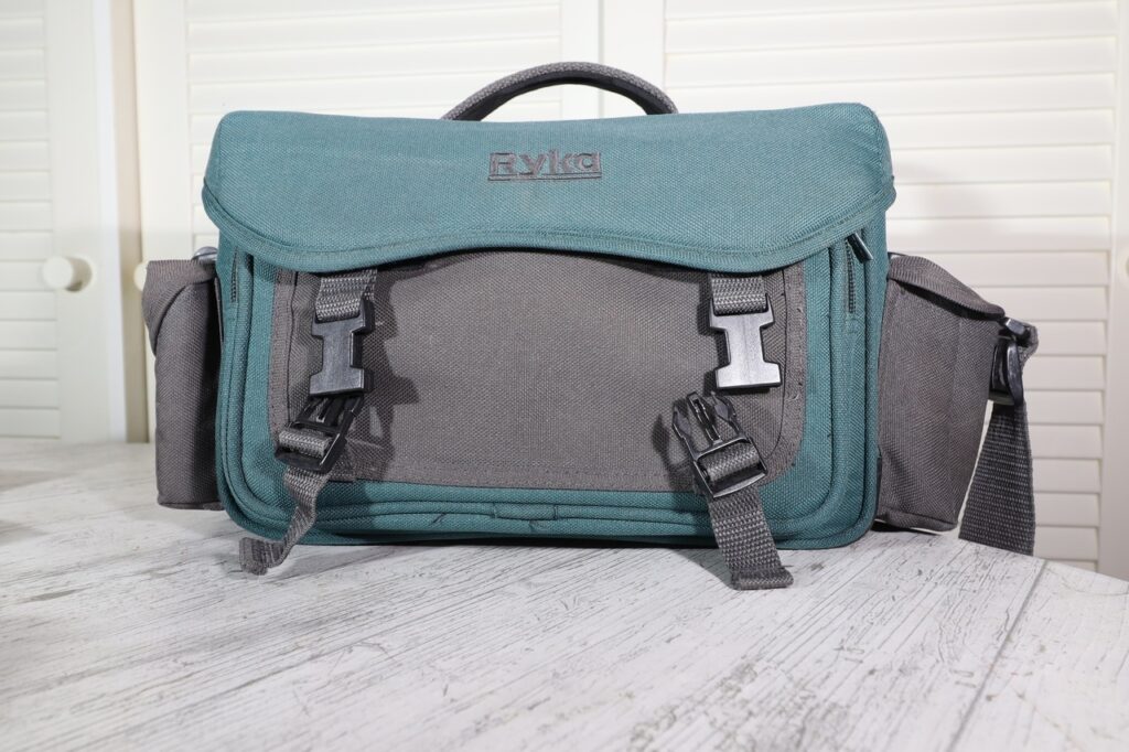
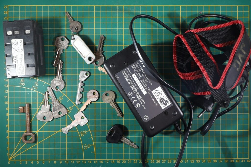
The camera seems indistinguishable from other JVC cameras in the same series:
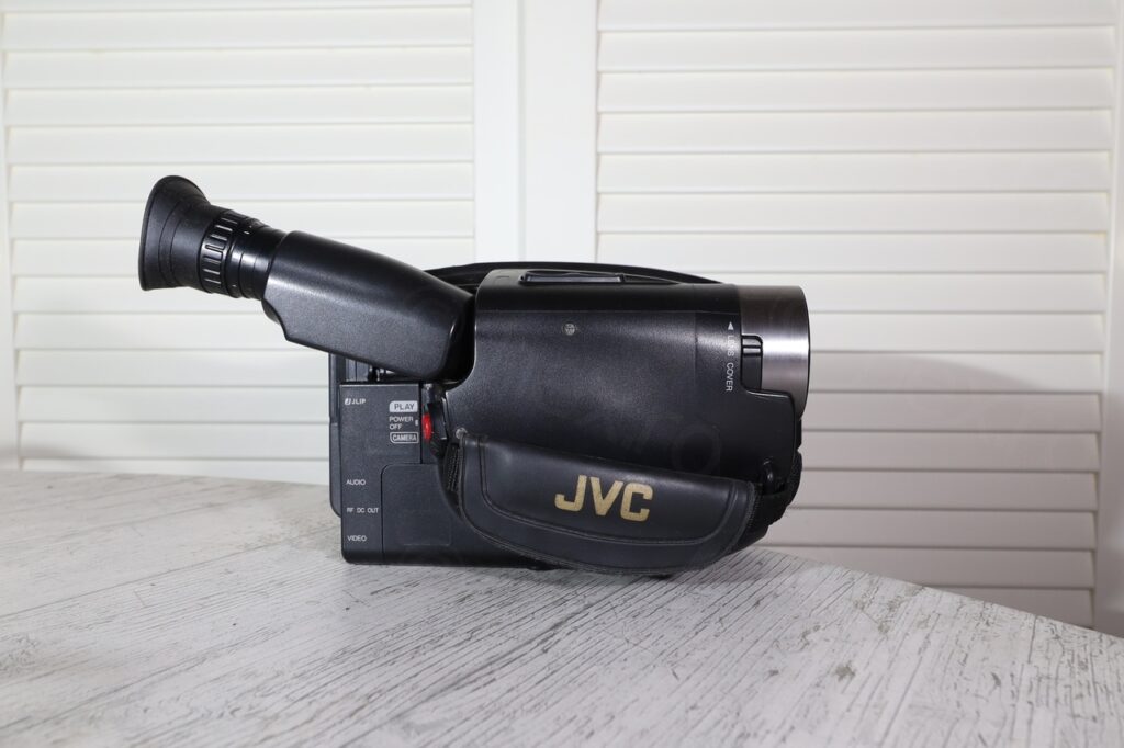
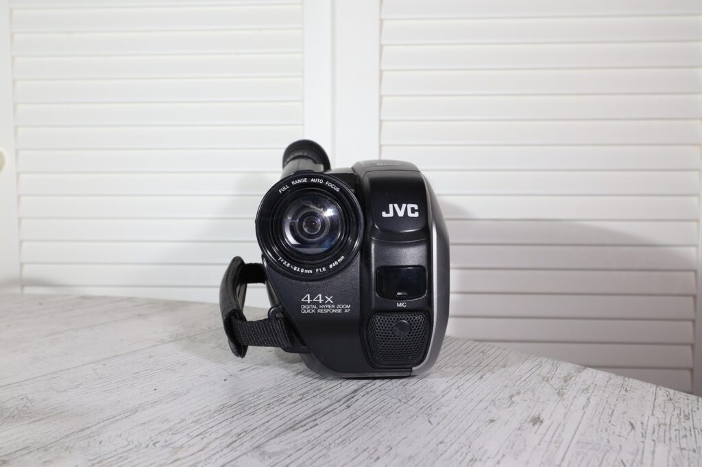
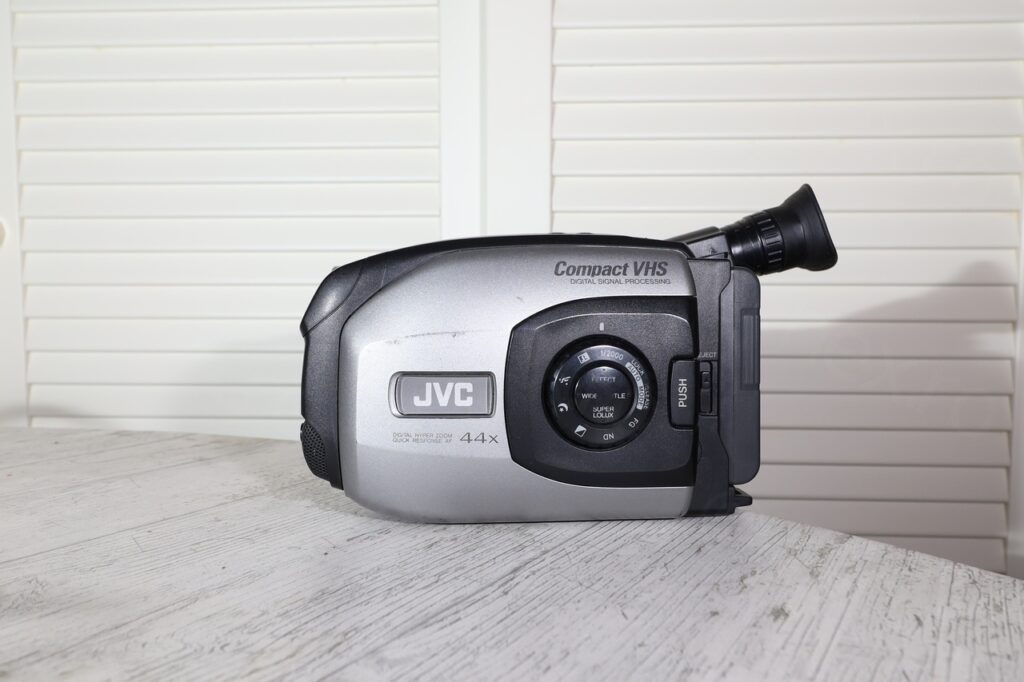
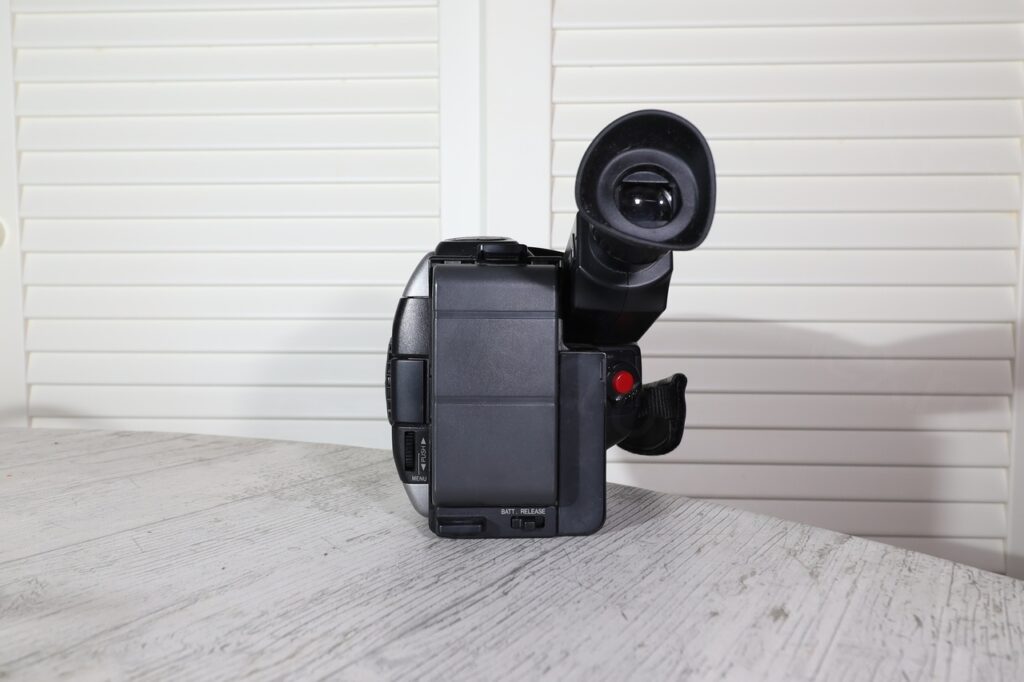
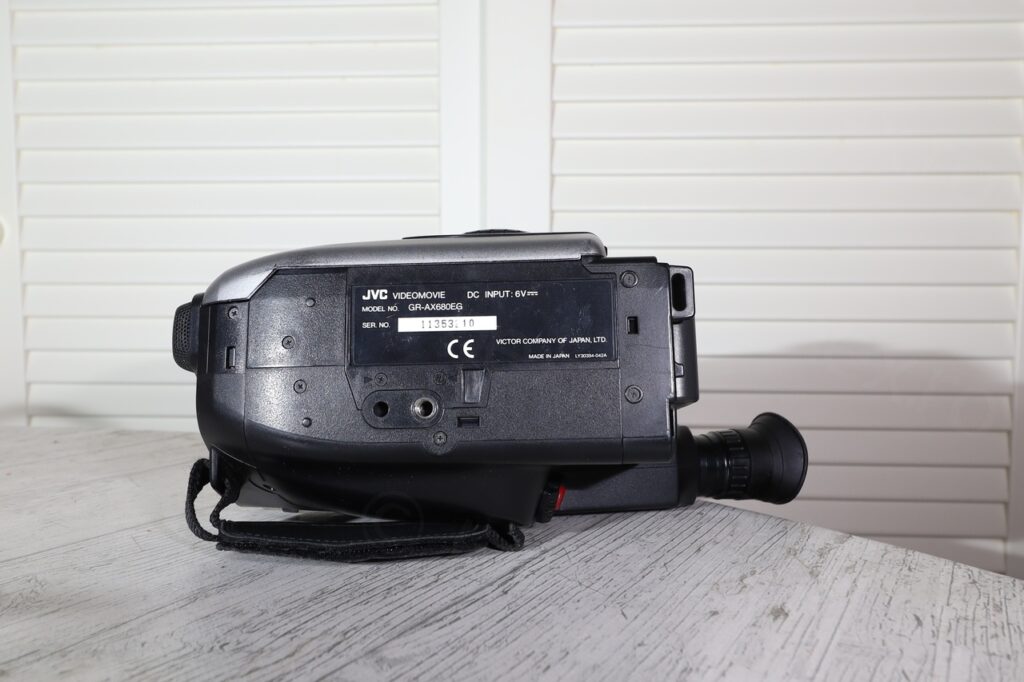
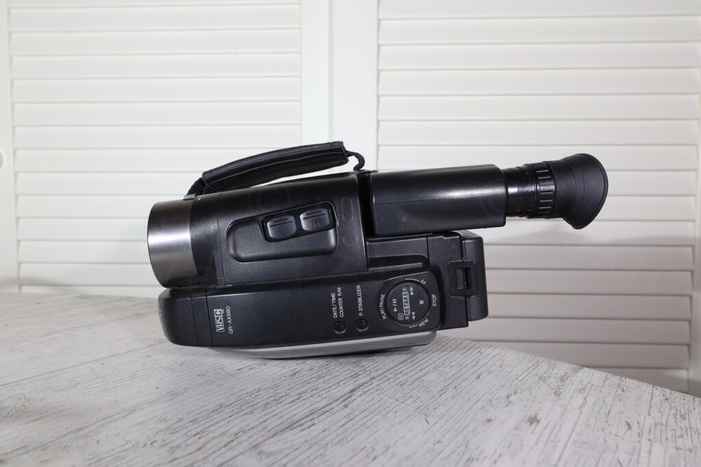
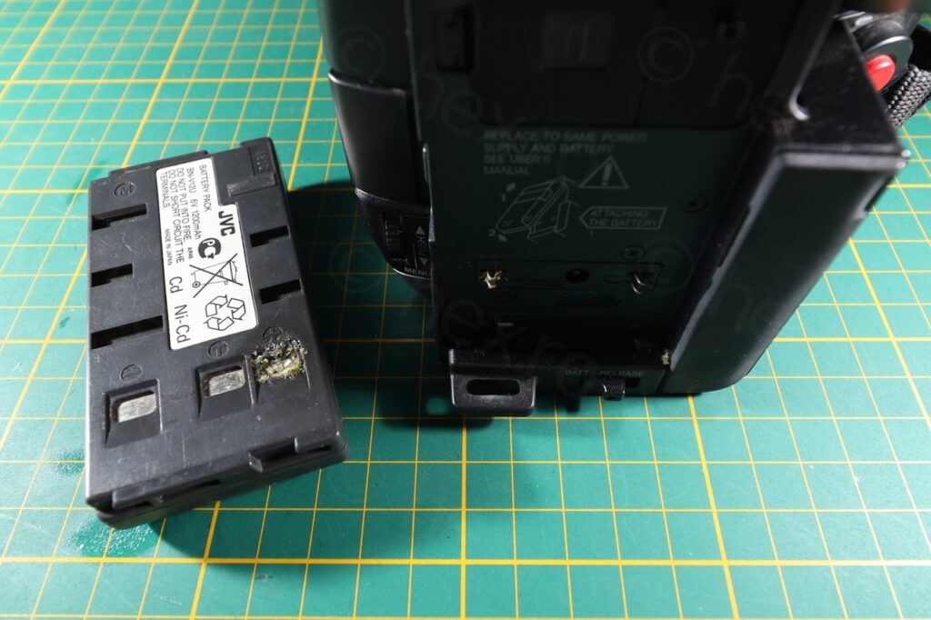
Surprisingly, the battery in this one didn’t leak as much though:
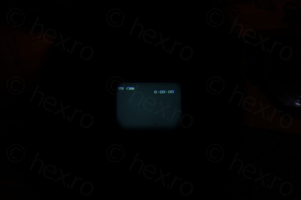
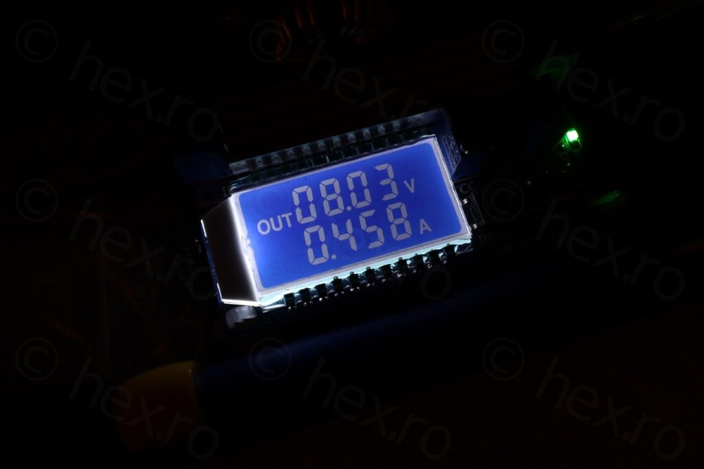
Despite the leak, I was able to power on the camera just for a quick check to make sure the CRT works:
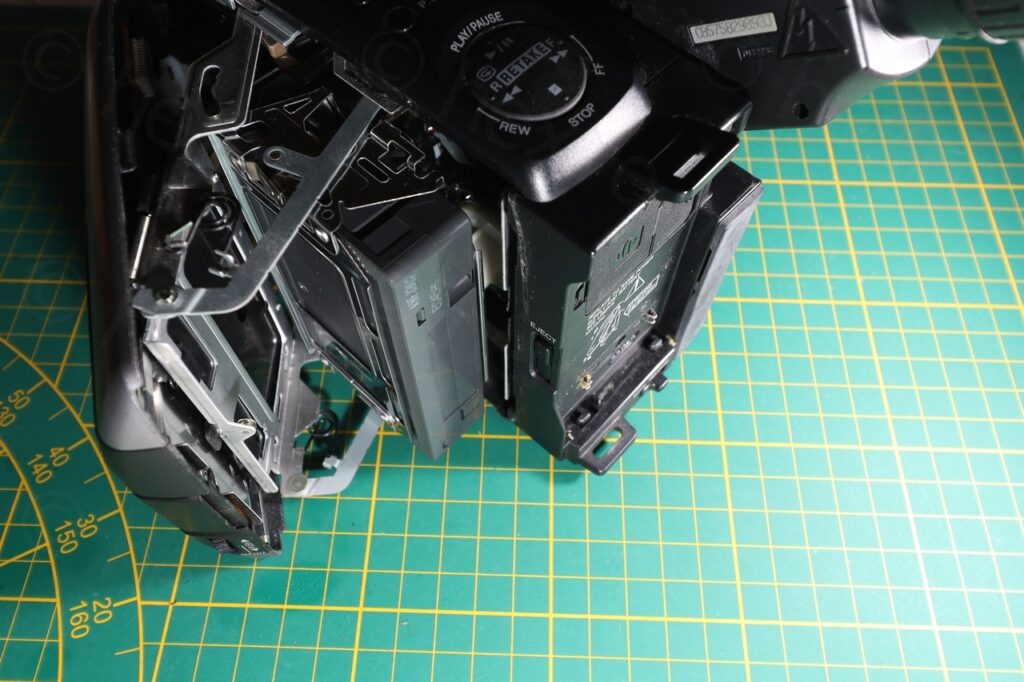
I proceeded with dismantling the JVC, I think I finally found the gist of it. The secret is removing the “Push” button that you have to keep pressed when closing back the tape compartment. There is a screw hiding there. After that, everything comes apart easily.
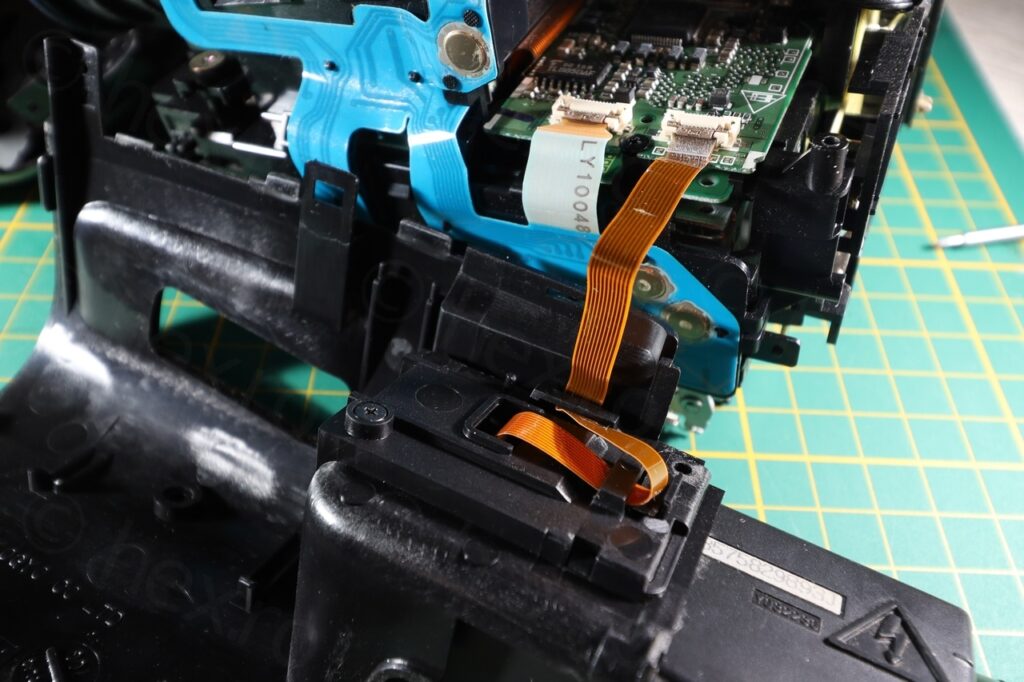
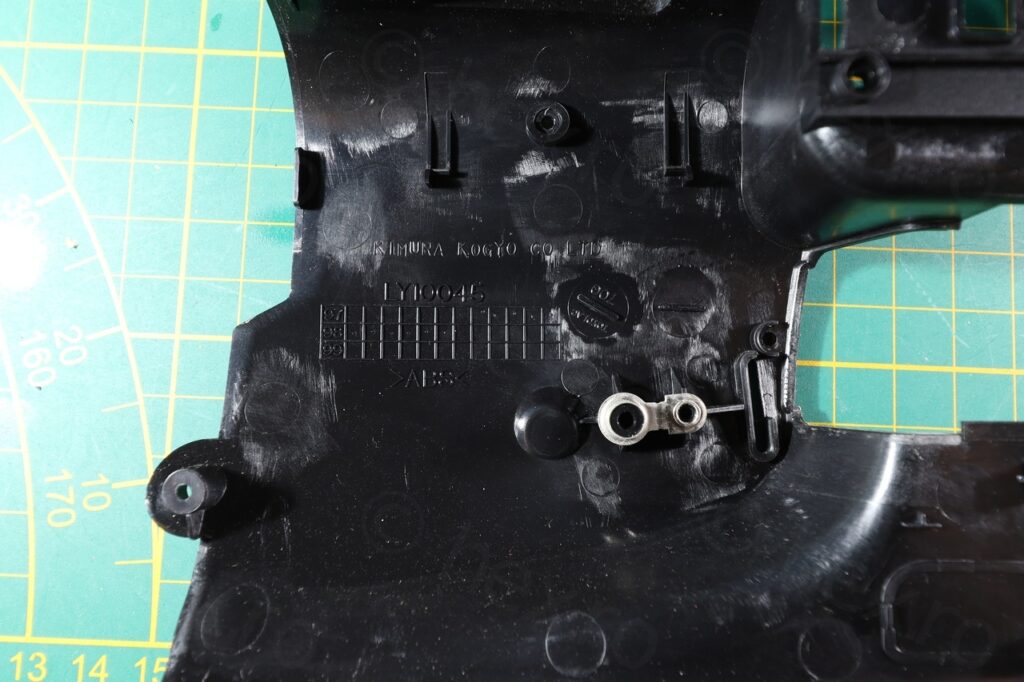
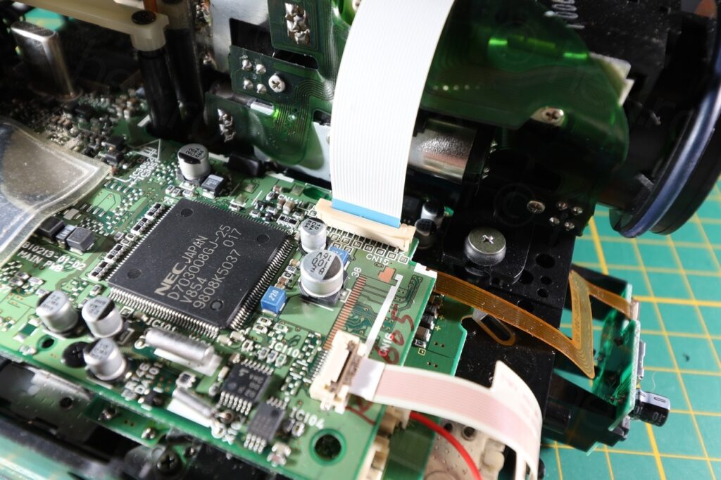
I try not to solder directly onto the CRT driver board (trying to preserve it as close as possible), thus, I’m always on the look out for some vertical connectors for the flat cable (even if wider than the cable) as it makes it easier to solder to these connectors instead.
However, with this camera, I got a different idea – use the flexible green circuit as a ‘breakout board’ for a flat cable connector:
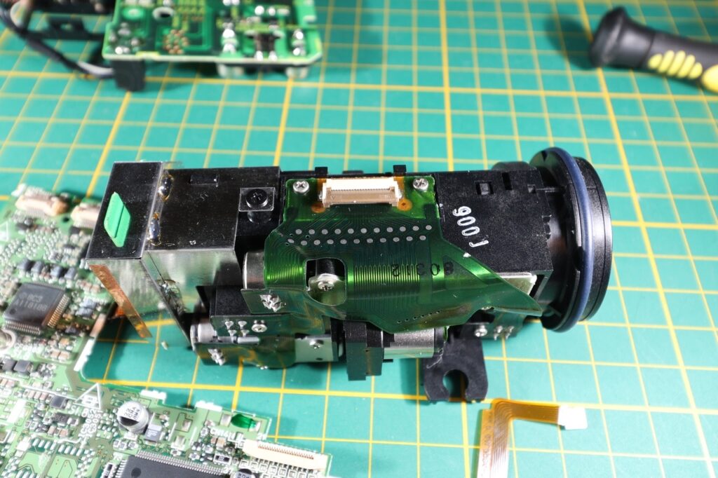
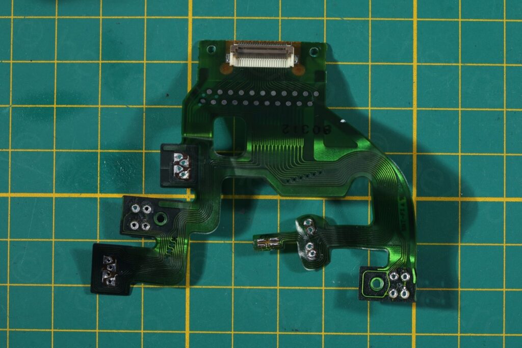
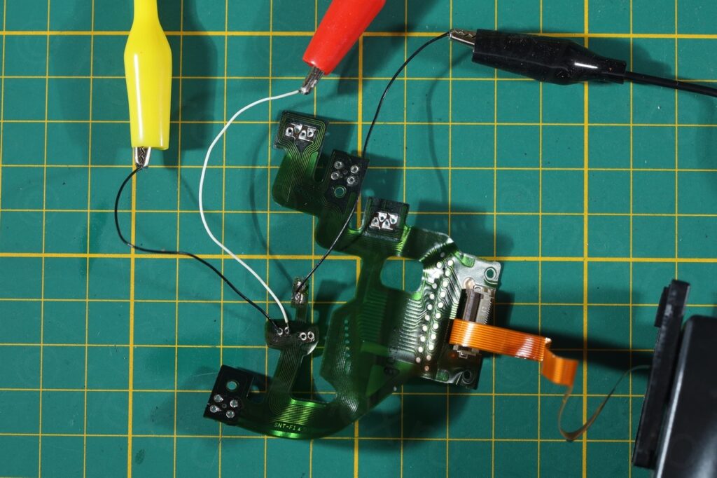
CRT
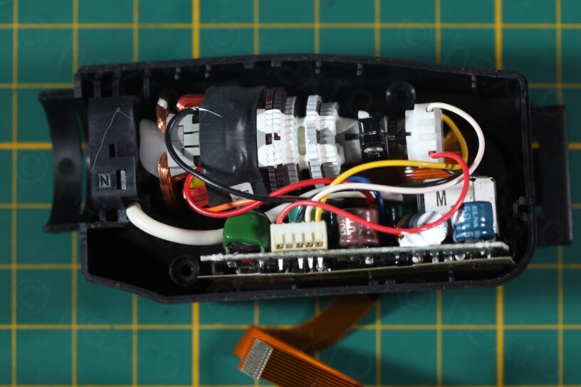
Dismantling this Electronic View Finder was also easy, and identifying the signal PINs was standard “modus operandi”: case of the FBt is connected to GND, there will be 2-3 more pins of the FBT that are connected to VCC. If there is continuity between the case of FBT to one of the pins on the flat cable, then it is GND. If other pins of FBT (which are not GND) are connected directly to a different to the flat cable connector, that is the VCC. Searching for the Video IN with some trial and error afterwards.
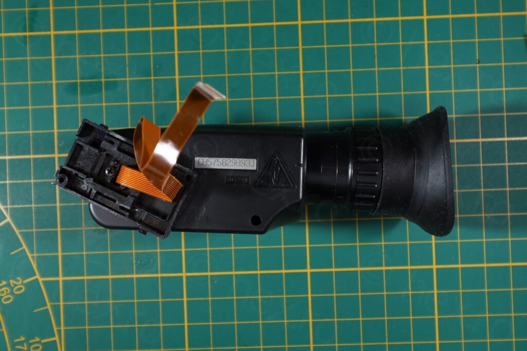
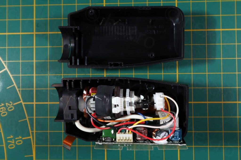
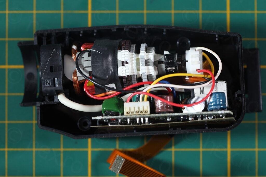
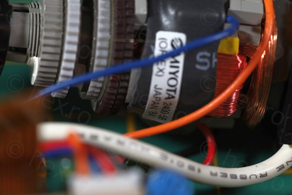
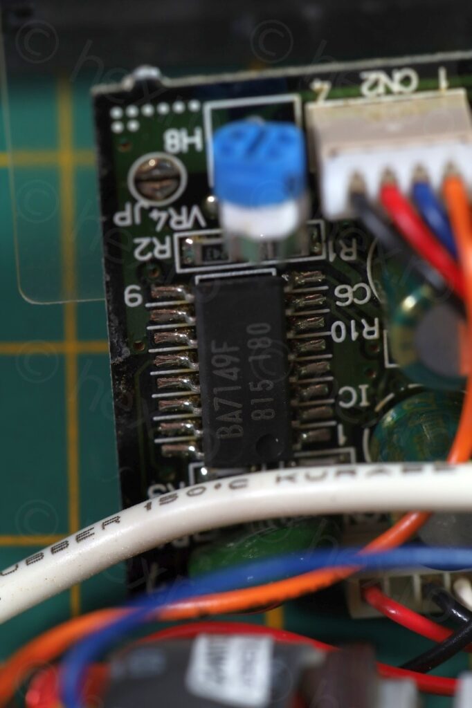
Results ?
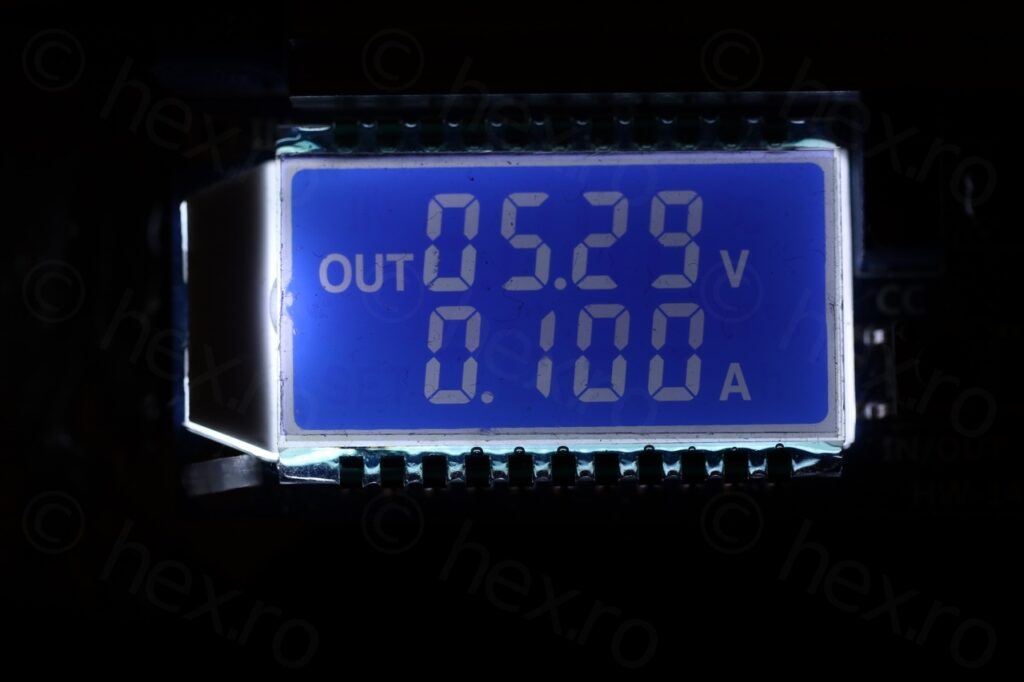

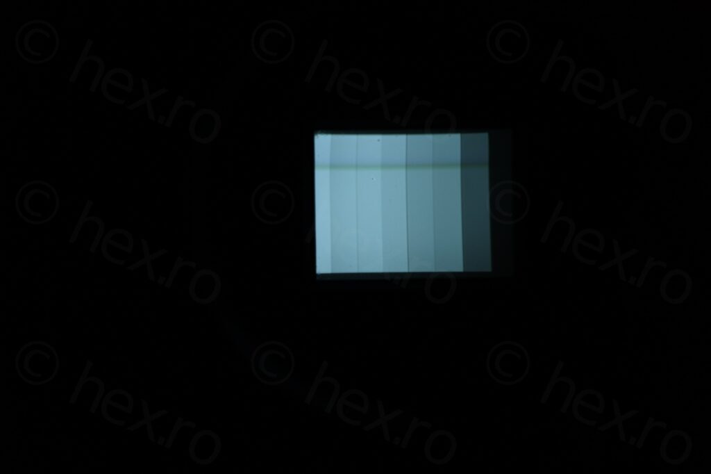
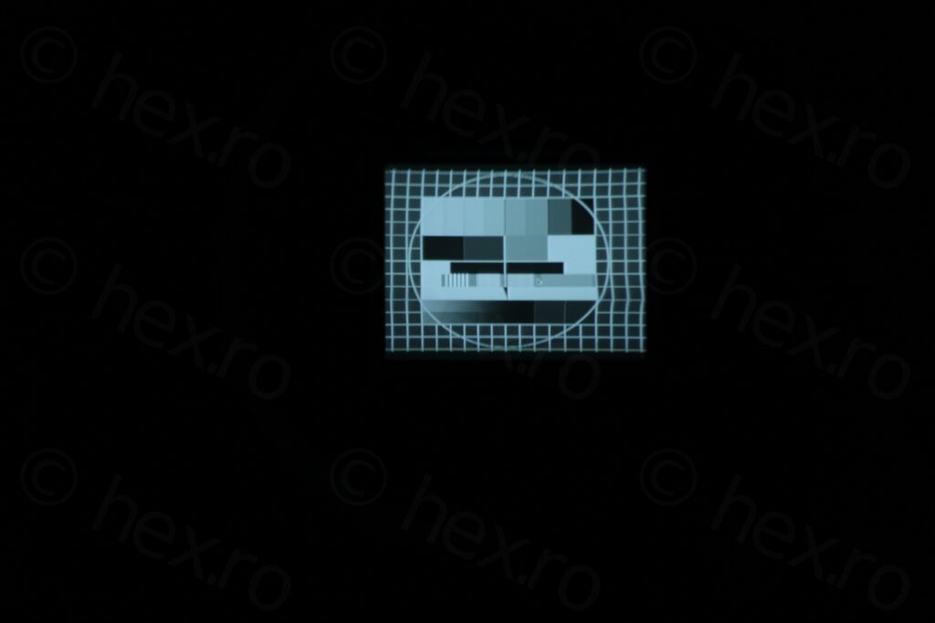
An easy camera to dismantle and EVF is in working order.
Tehan
hi! where can i get that test pattern ?
viulian
Do you mean this one 🙂 https://en.wikipedia.org/wiki/Telefunken_FuBK ?
Tehan
yeah thats the one! Thanks man!