Table of Contents
Introduction
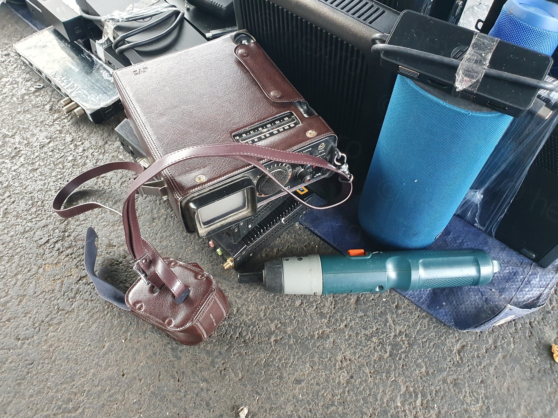
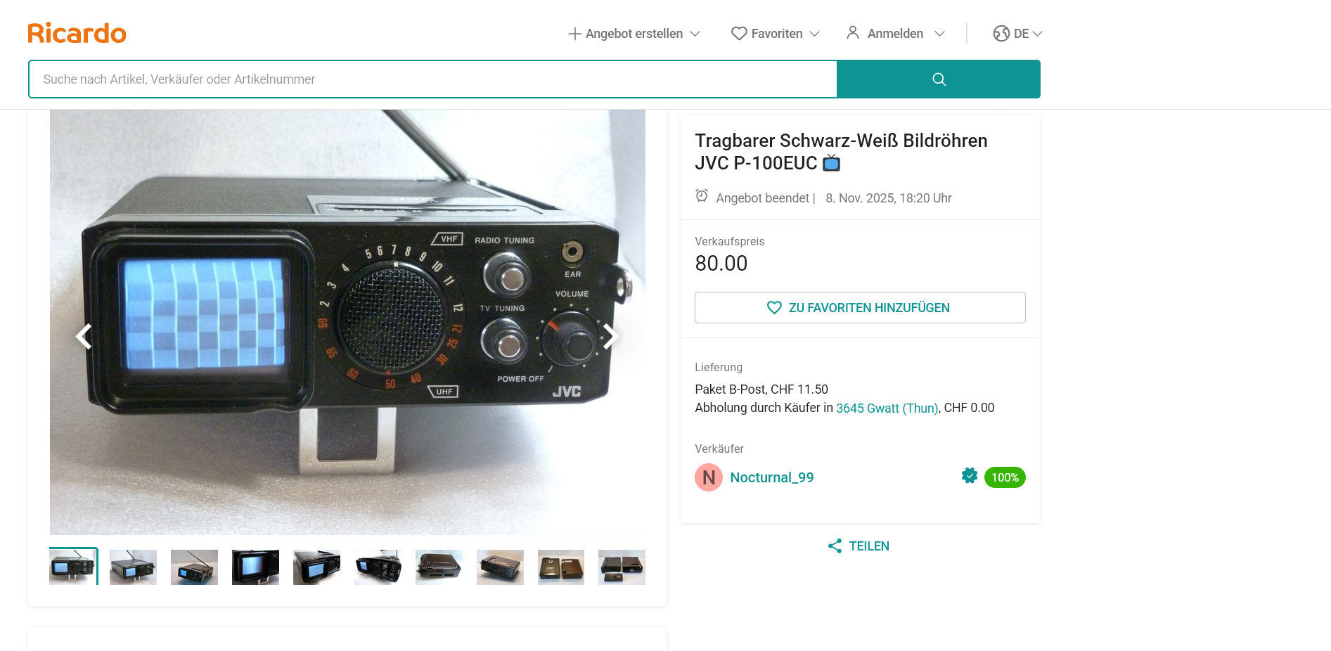
I almost missed it. It was early morning, not much light flooding the market – I was looking down at a bunch of old mini PCs on the floor – thinking, do I need an old PC ? “I have a bunch of them already”, “they don’t get much use … “, “there is no point in even looking at their specs”. But as I was turning away, a thought appeared: “did I just see a tiny CRT ?!”
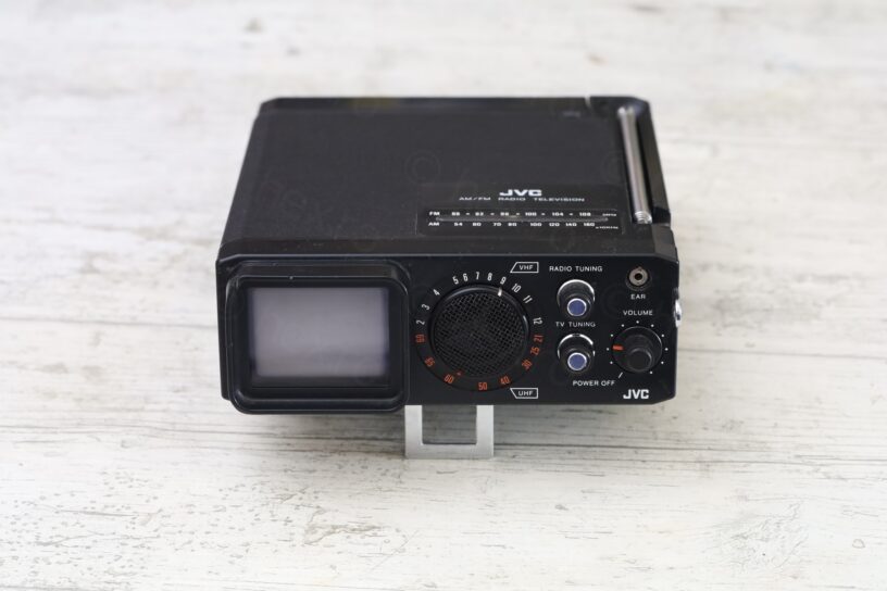
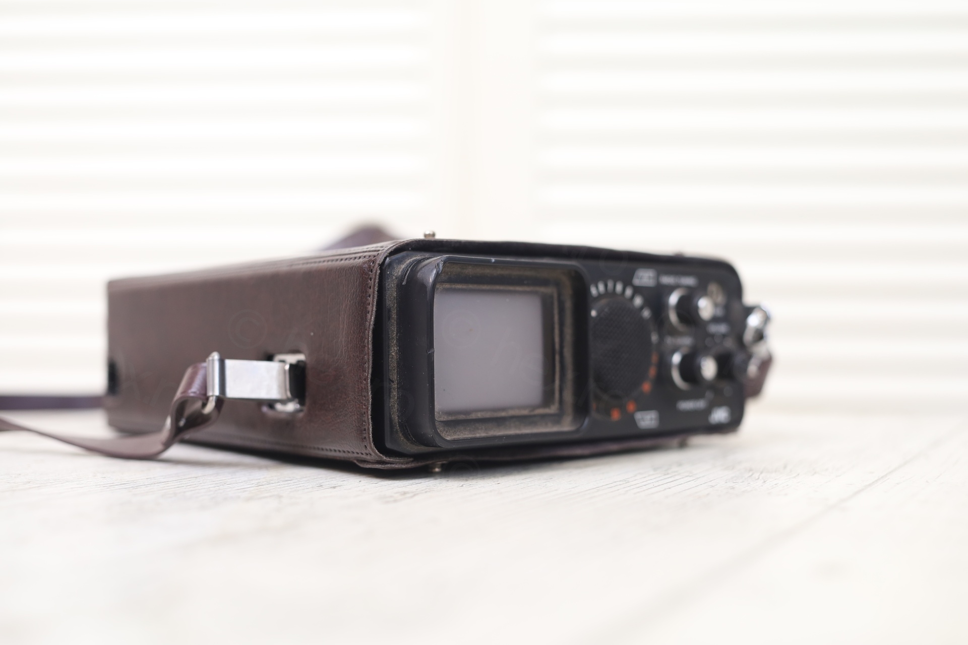
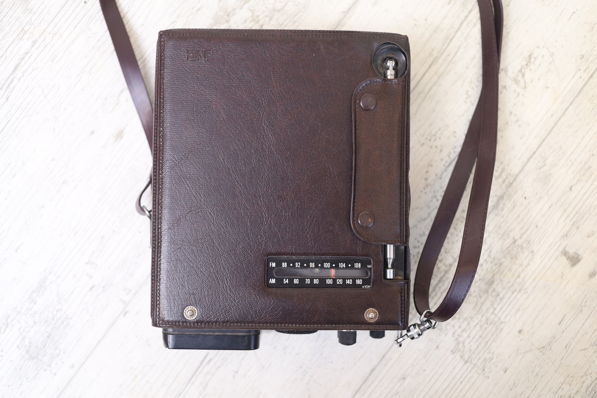
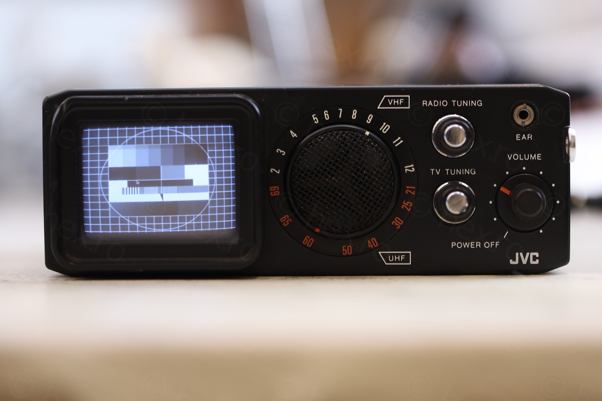
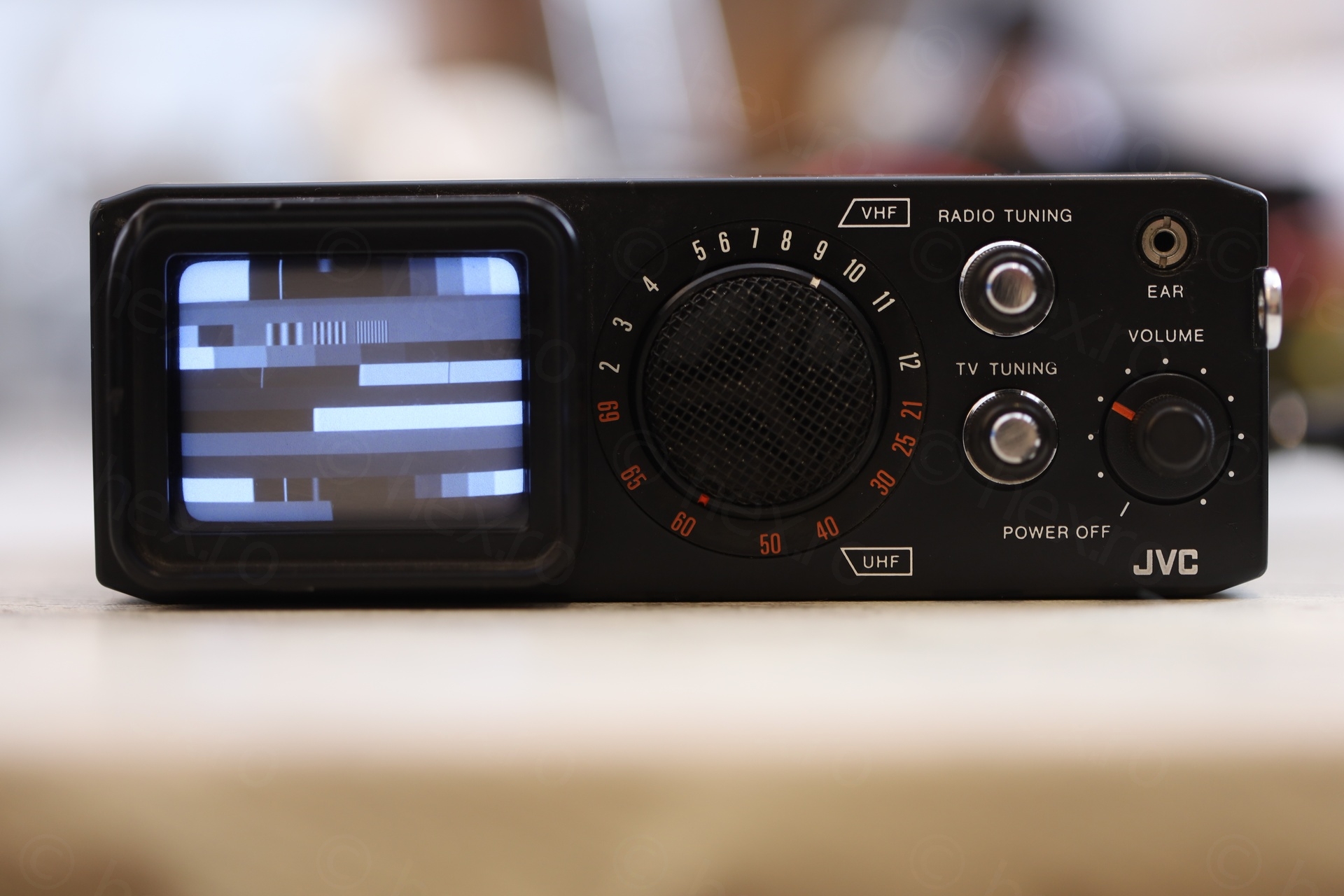
I looked back to find it. And yes, there it was:

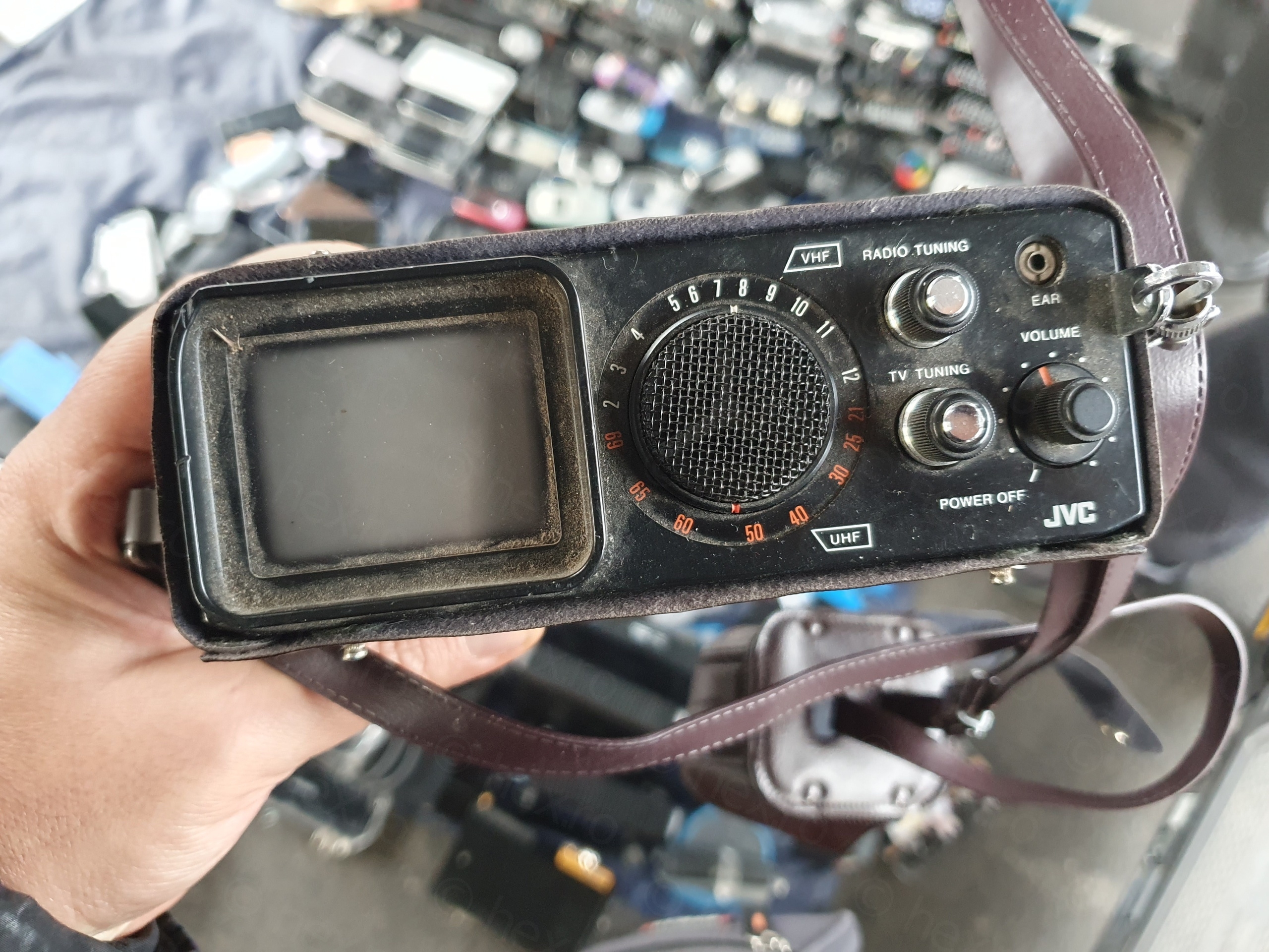
I had mixed feeling about it. The plastic lip surrounding the CRT had a nasty hit and was dented in (you can see it on lip surrounding the screen, the top left). There was no power adapter and additionally, the plug was custom / not a barrel jack. It was also missing the (magnifying?) visor that one could slide over the CRT (for improved viewing under bright outdoors). Even if it had the vinyl cover, it was supposed to also have a cap over the CRT (due to the dust buildup on the CRT, I realized this cap was missing for a very long time …).
I shared my worries with the seller, a bit of back and forward, and … reluctantly… I bought it.
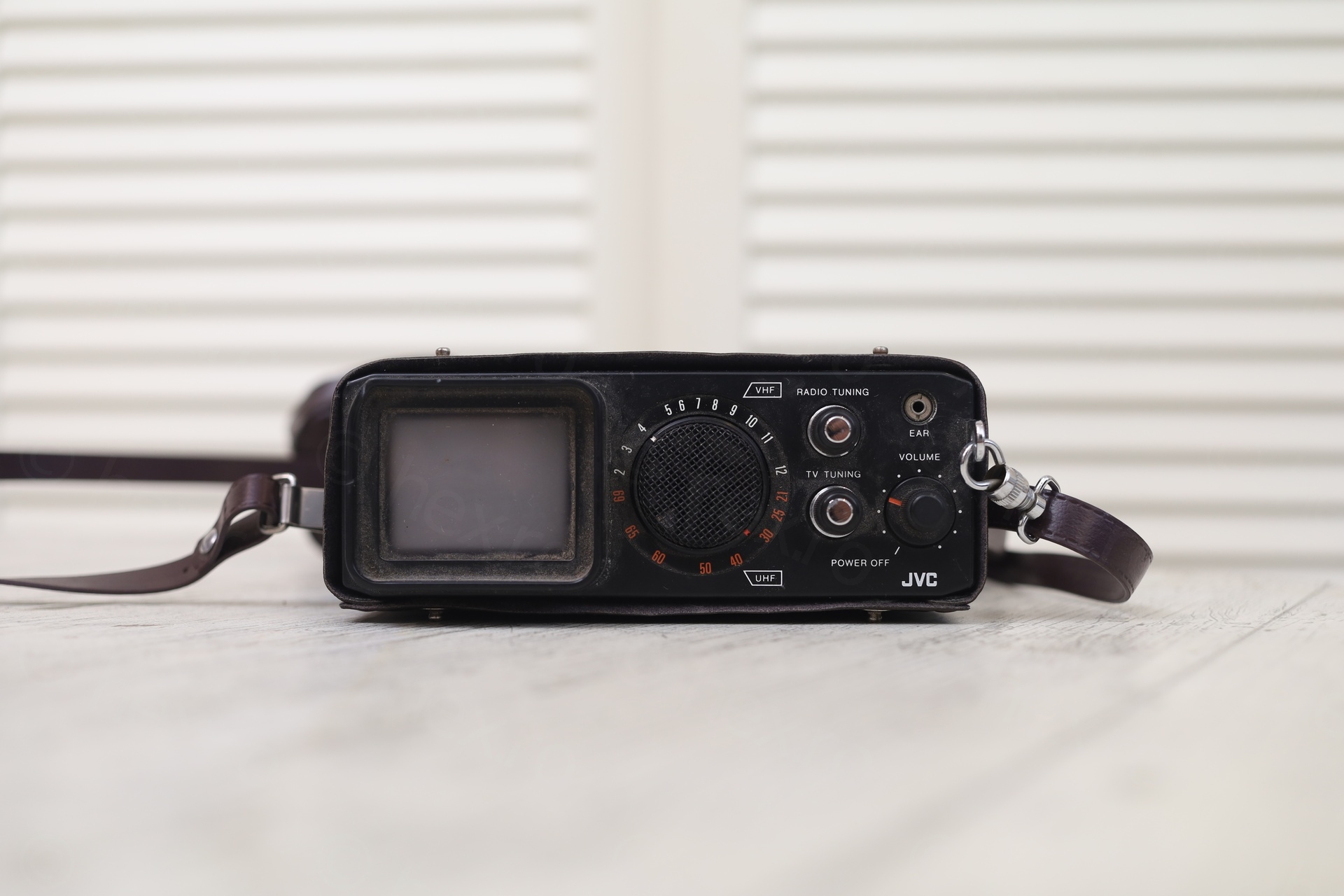
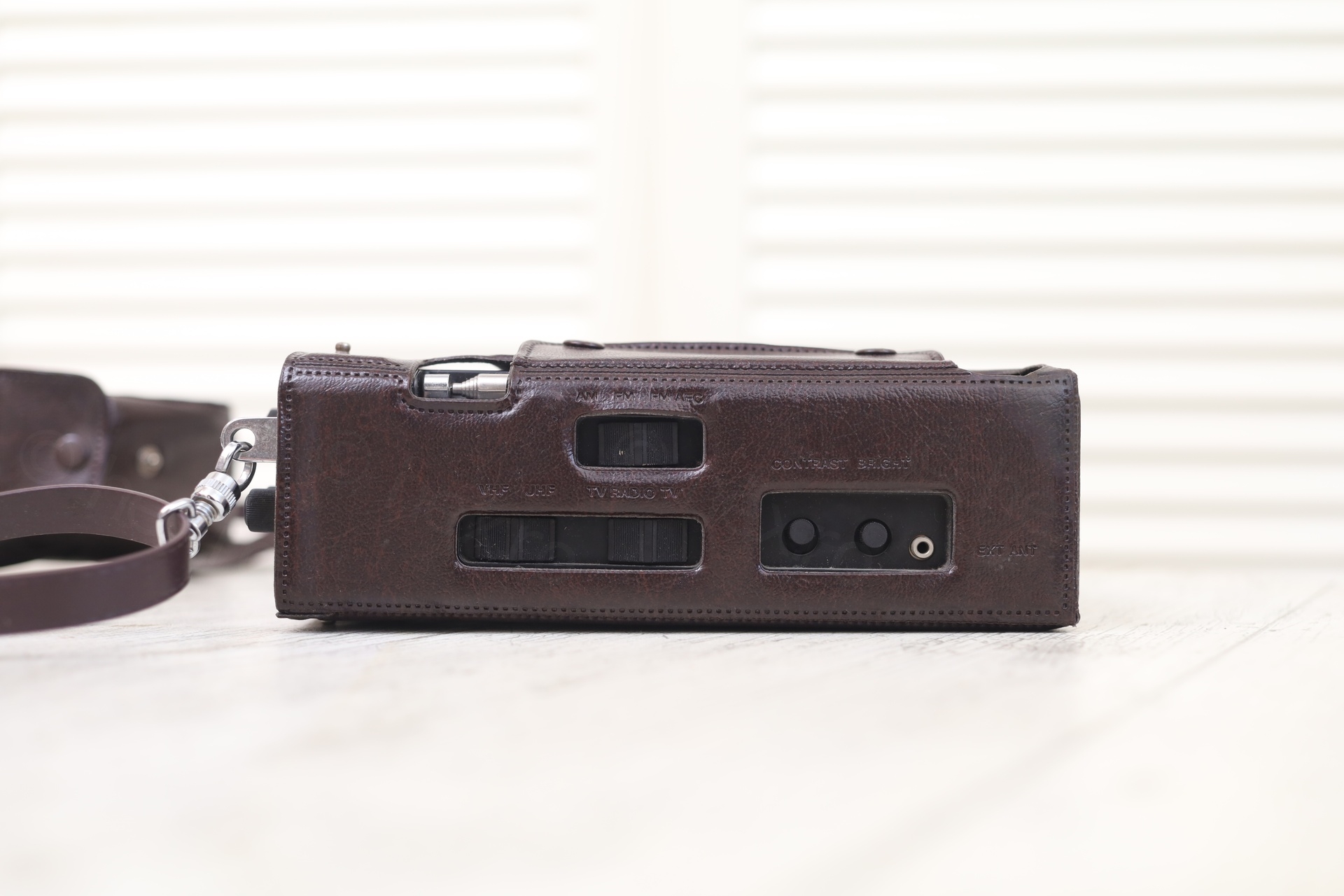
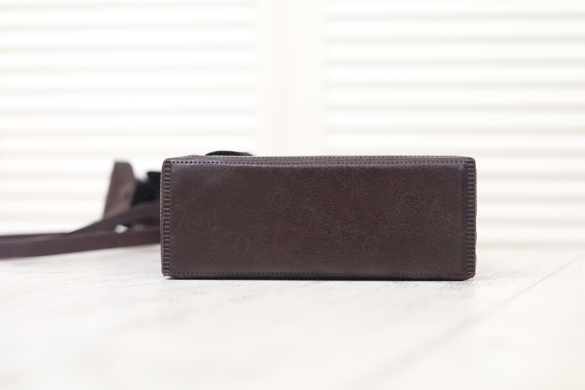
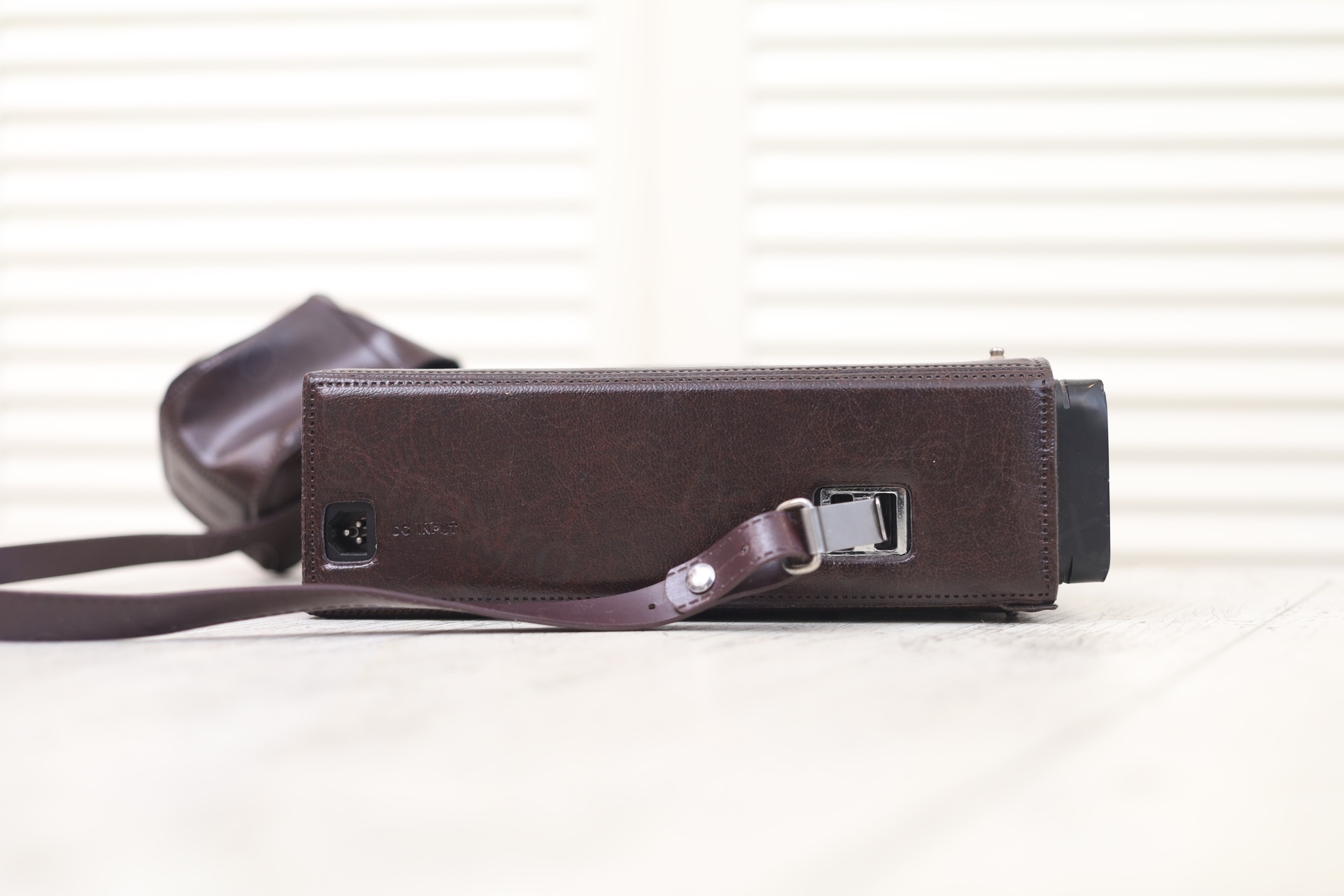
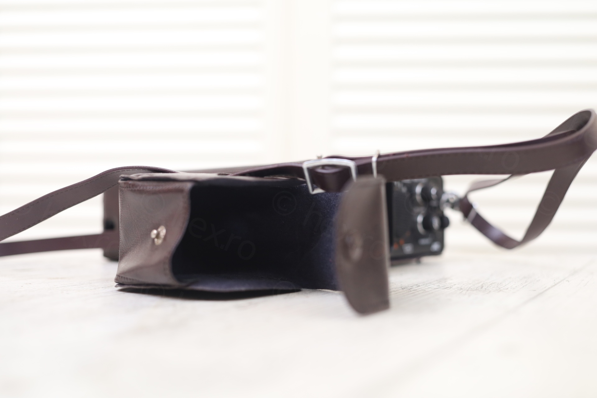
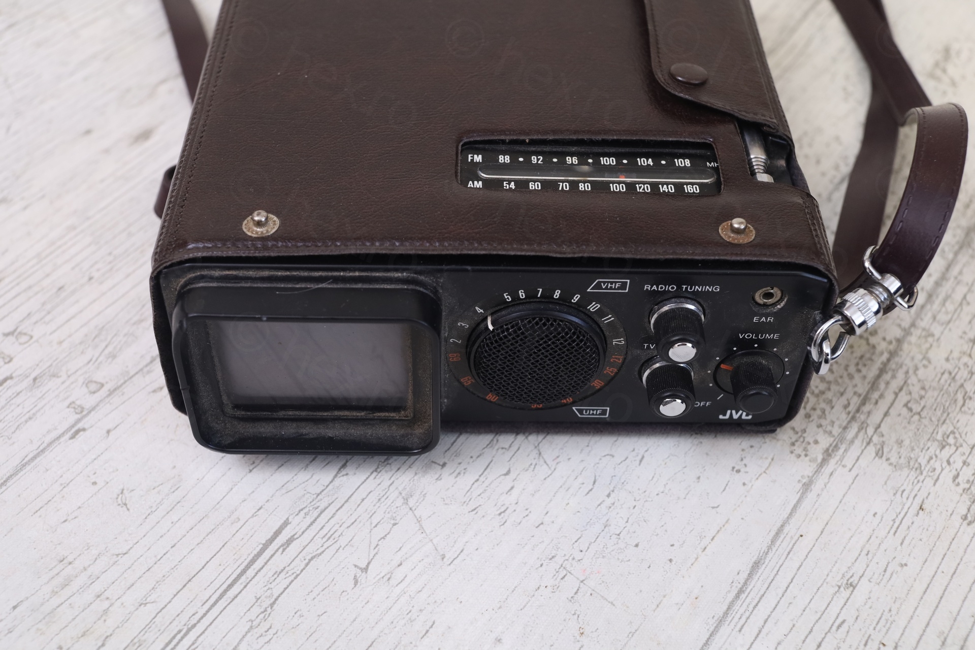
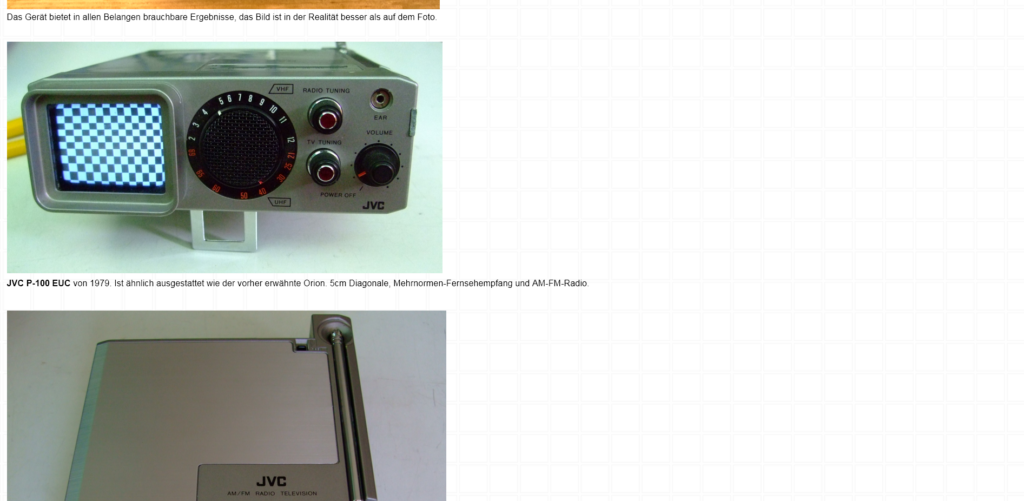
Here are some more photos:
Tests
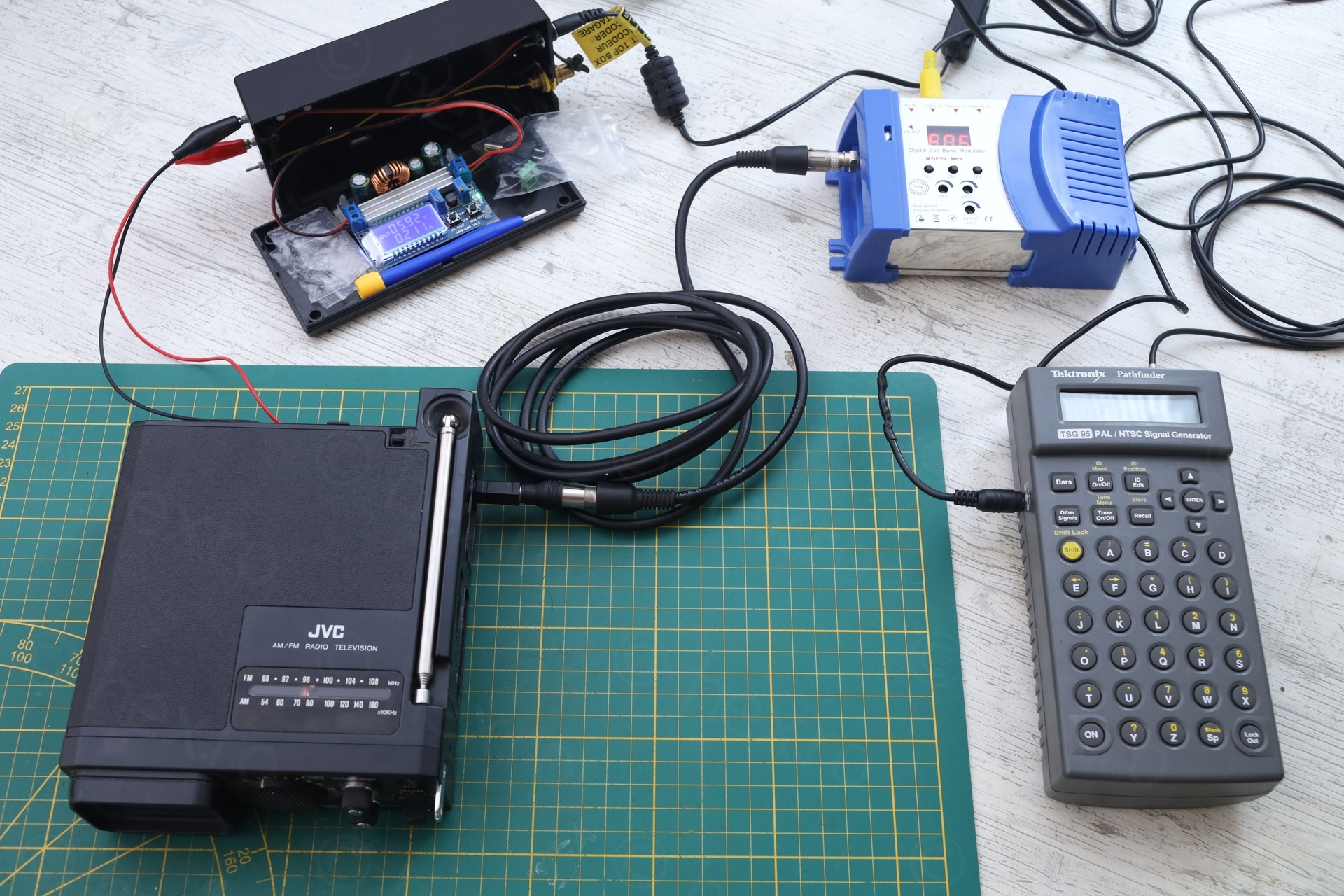
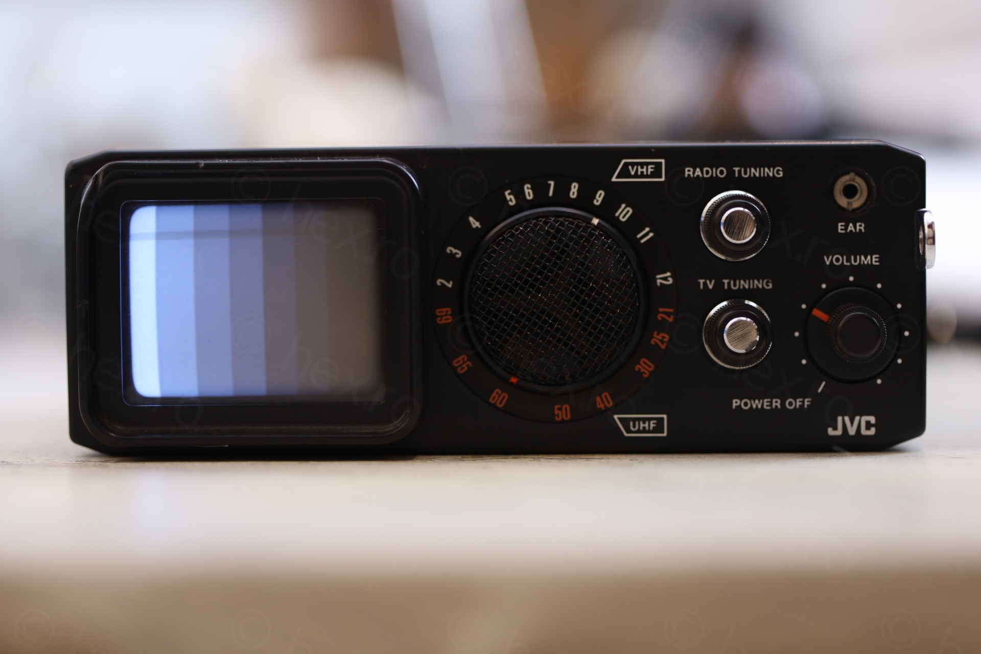
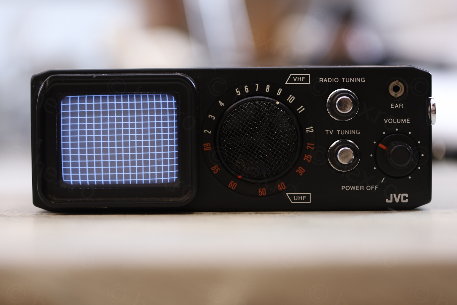
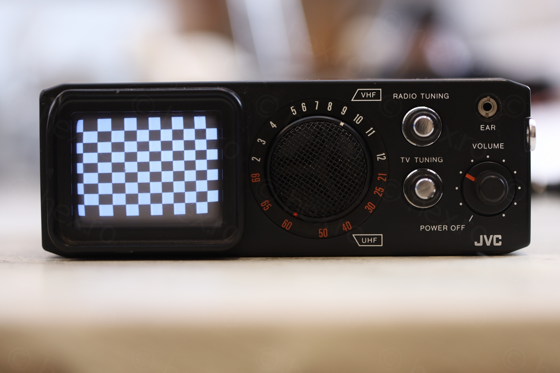
The TV has an External Antenna jack, but it is 2.5mm. I needed a mono adapter to convert from the 3.5mm to the 2.5mm. I used the Tektronix TSG95 as Video Signal Generator + a small adjustable power supply set to 6V, as well as the M69 RF Modulator:
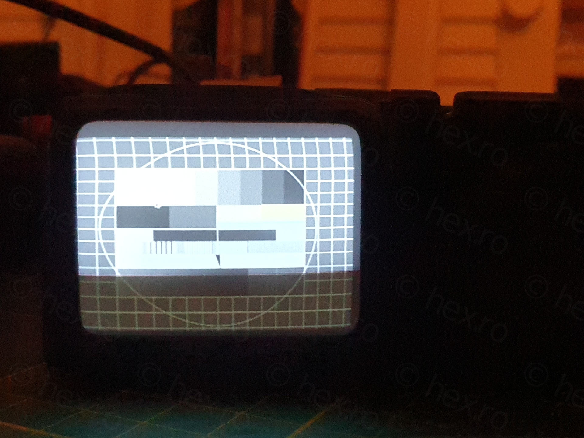
Unfortunately, there were strong Vertical and Horizontal linearity issues, where the Top Right squares were squished, while the Bottom Left were much larger. And the left line wasn’t even appearing using “Pal Safe Area” from the Tektronix TSG95:

The little TV has no controls accessible from the outside, so the only way to try to sort the problems was to open it up.
Opening up
This content refers to cathode ray tube (CRT) equipment which may contain components operating at high voltage.
Hazardous voltages may remain present even after the equipment has been disconnected from the mains supply. Improper handling may present a risk of electric shock.
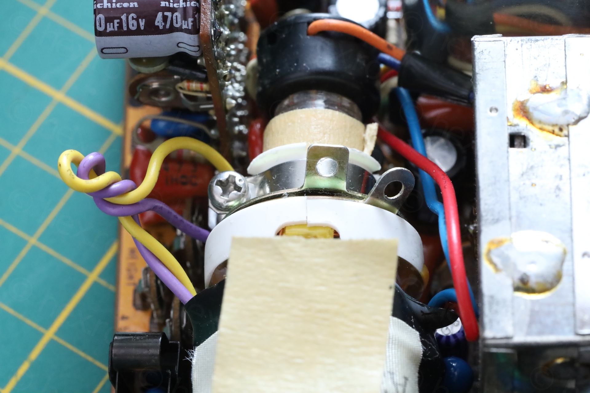
Opening up is easy, removing the visible screws and the case comes apart. Inside, there are plenty adjustment pots …
… unfortunately, they did not help with my problem. I did use a ceramic screw driver, since they are so close to the CRT, I was afraid of not touching something high voltage.
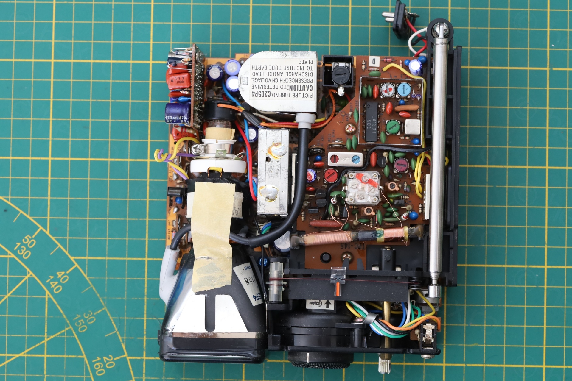
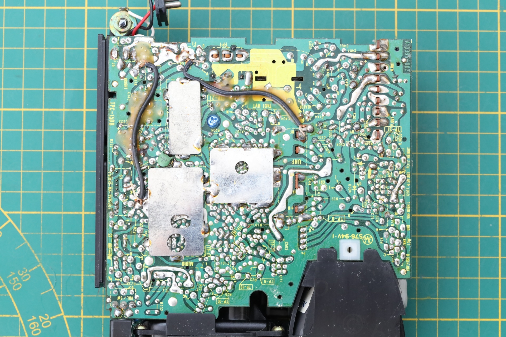
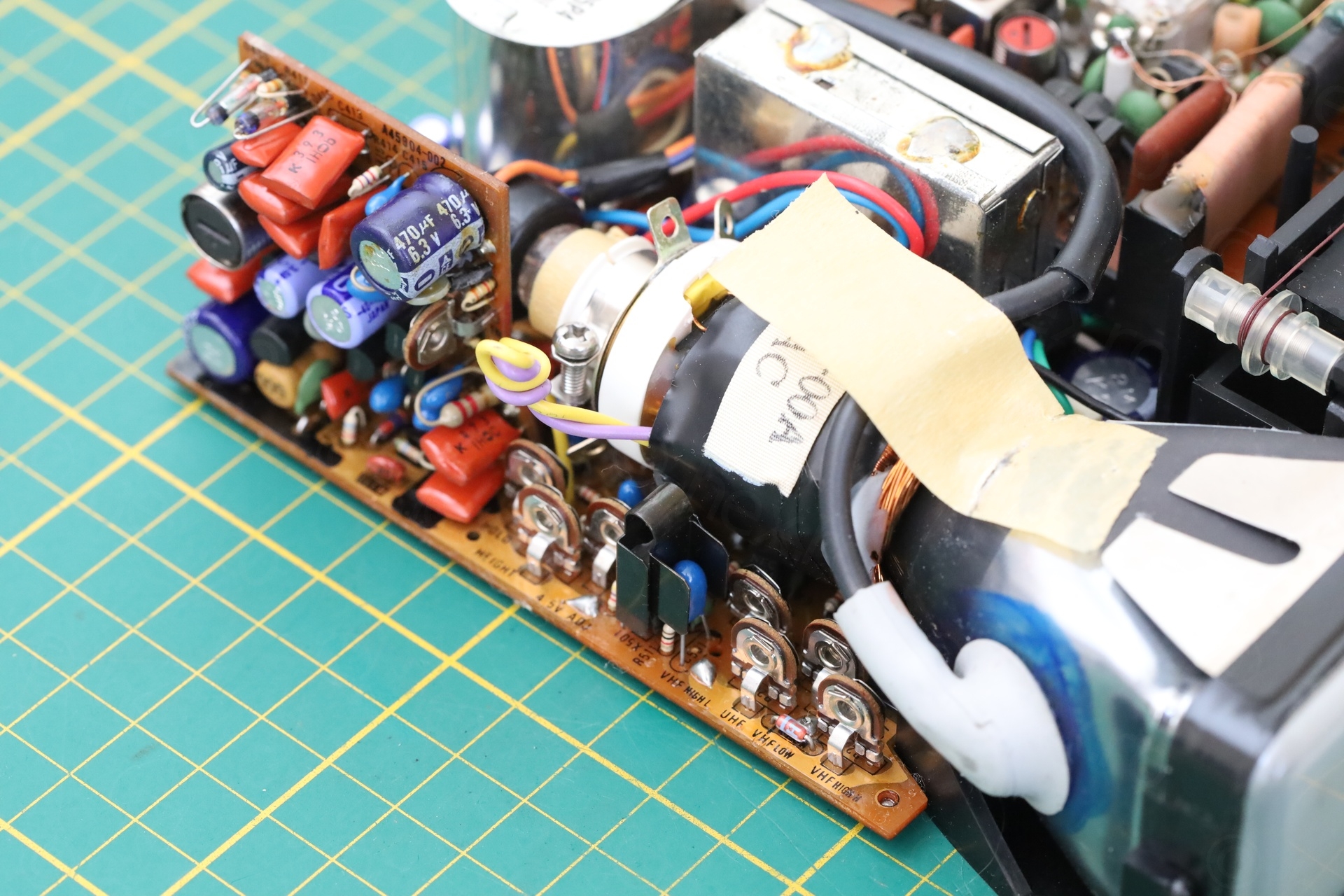
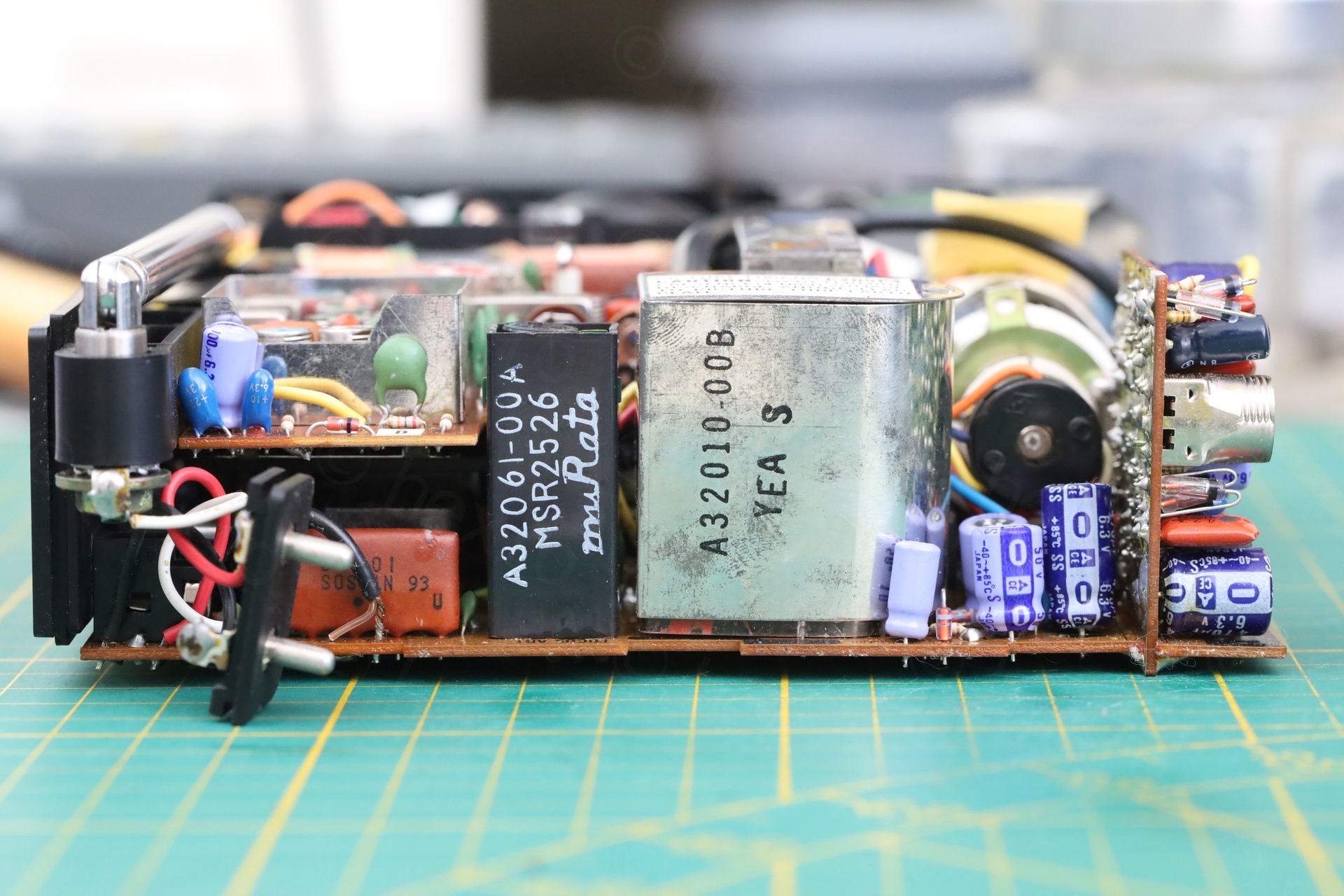
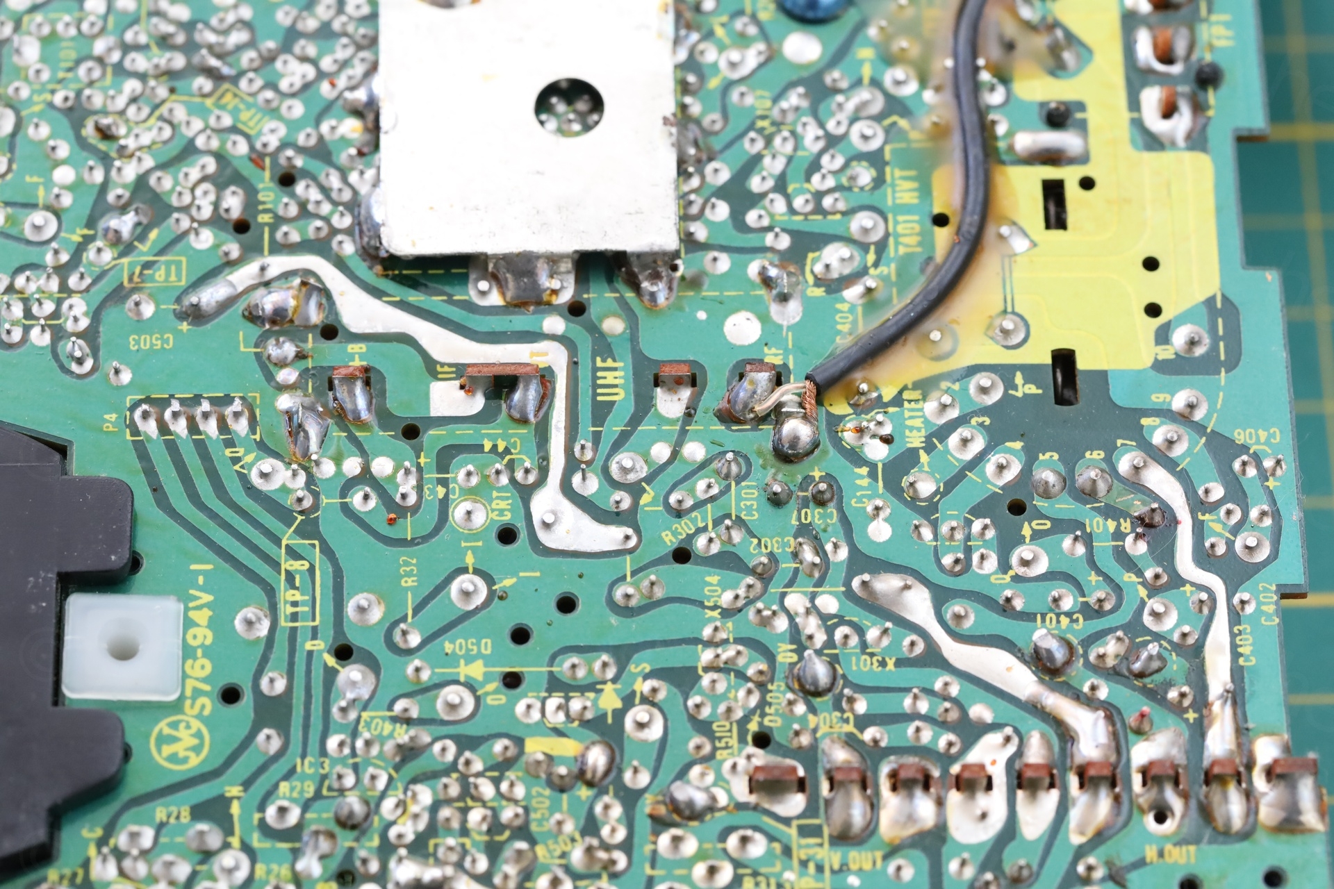
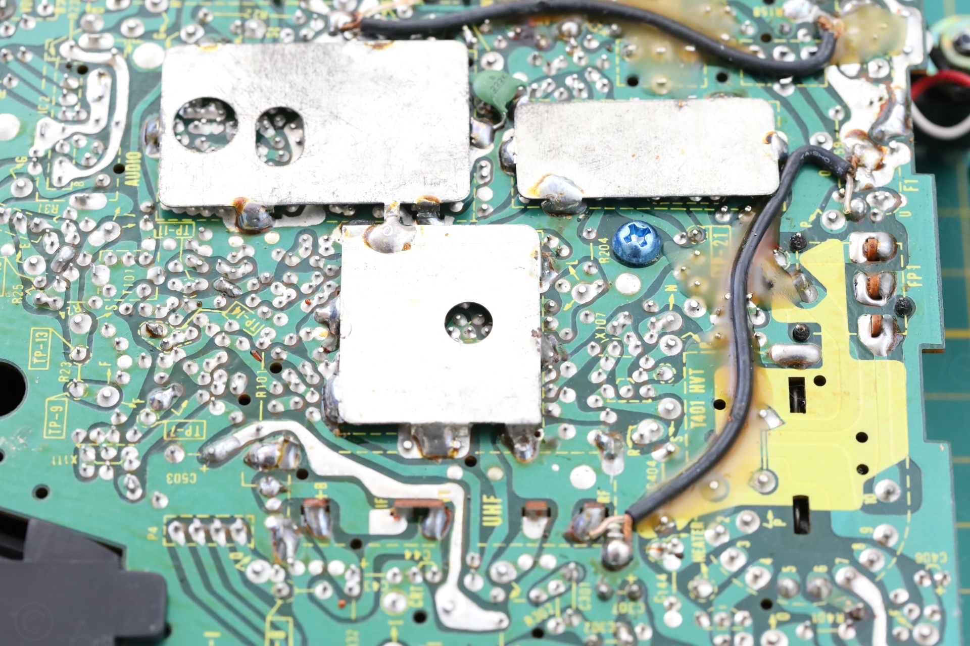
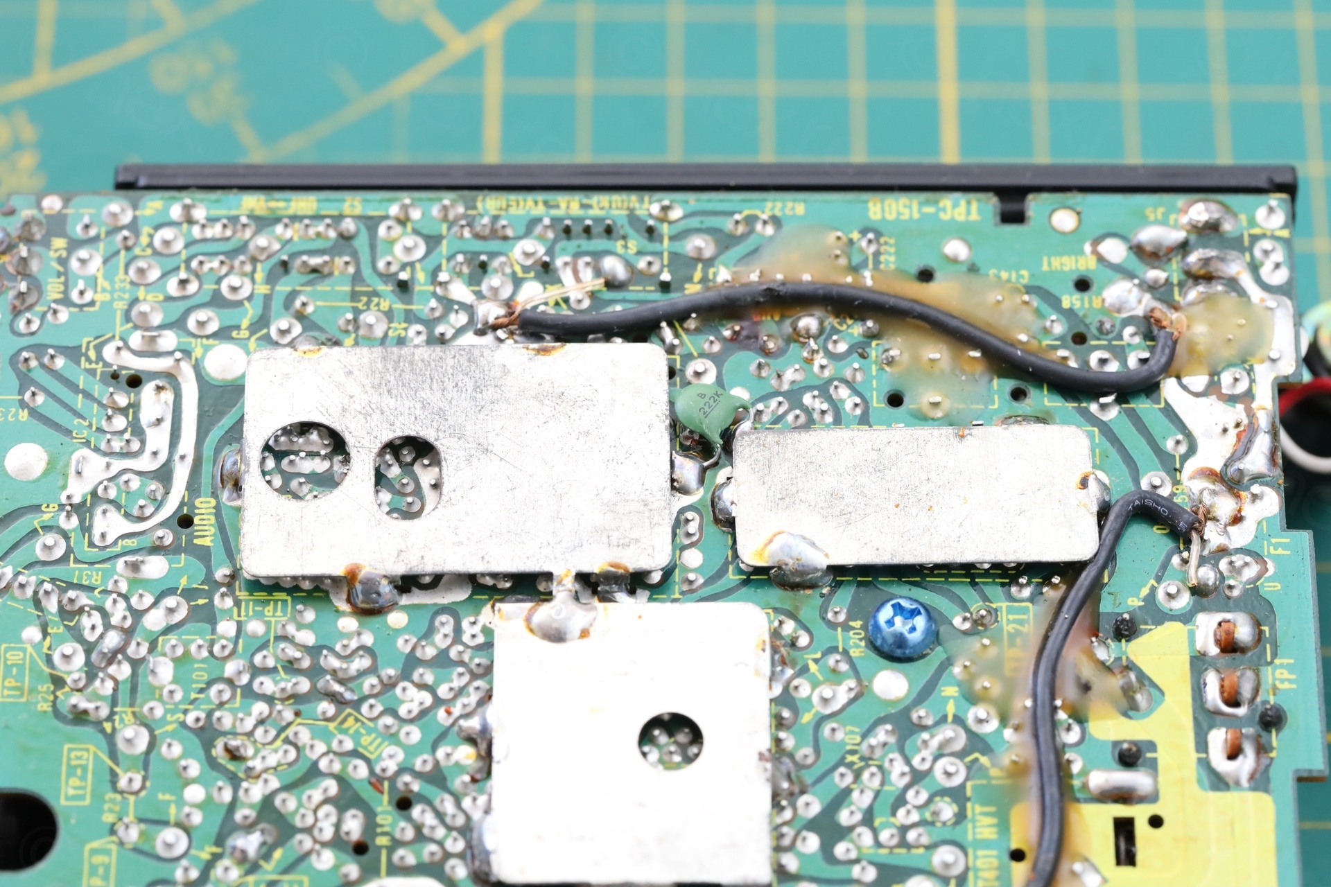
Here are few more photos with the insides:


Attempted repairs
This blog would be too long to list all my attempts at diagnosing this TV. Voltages and oscilloscope traces matched, although the service manual shows the oscilloscope traces too tiny to be able to meaningfully make a difference.
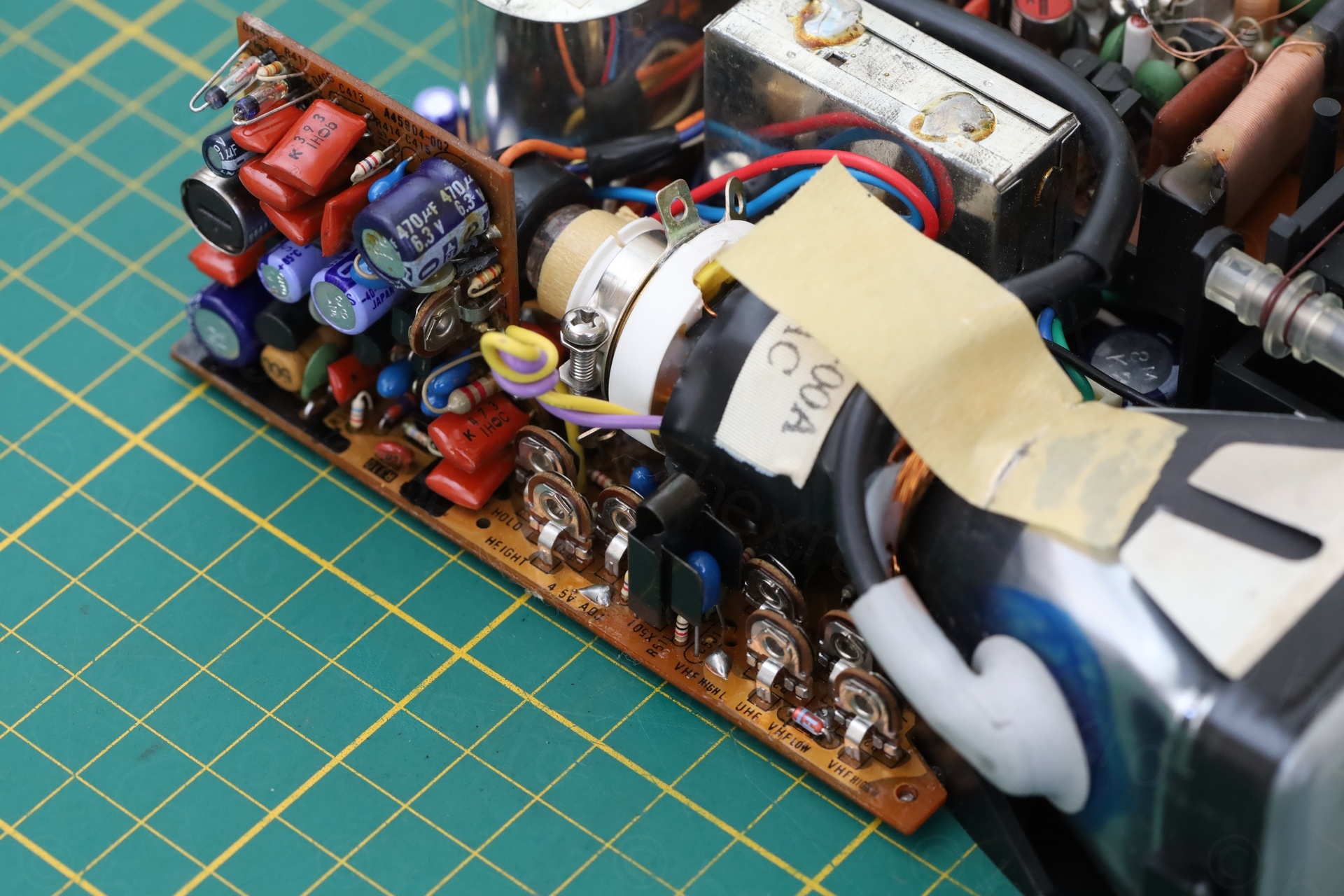
Replacing Capacitors
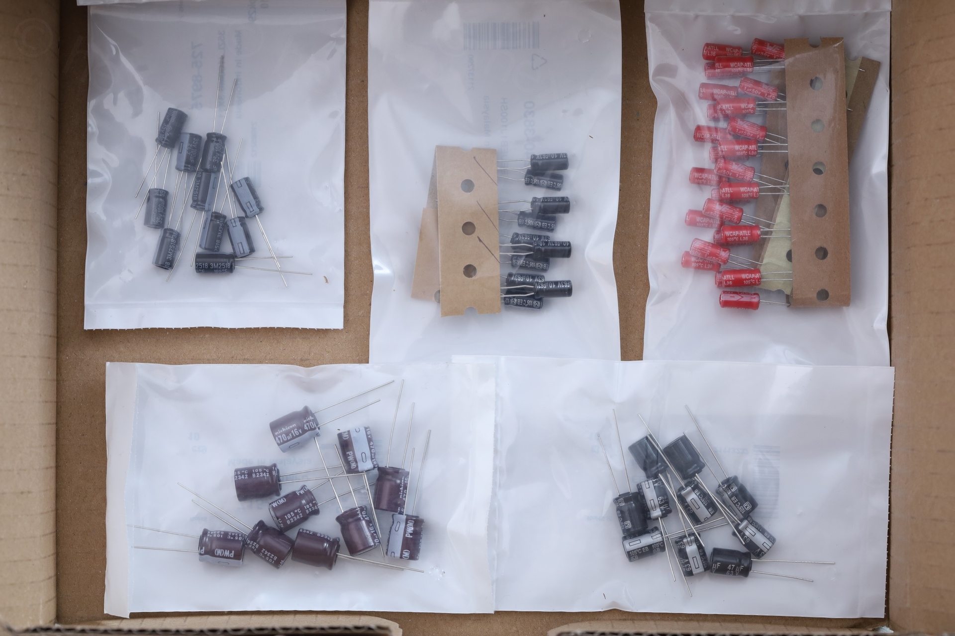
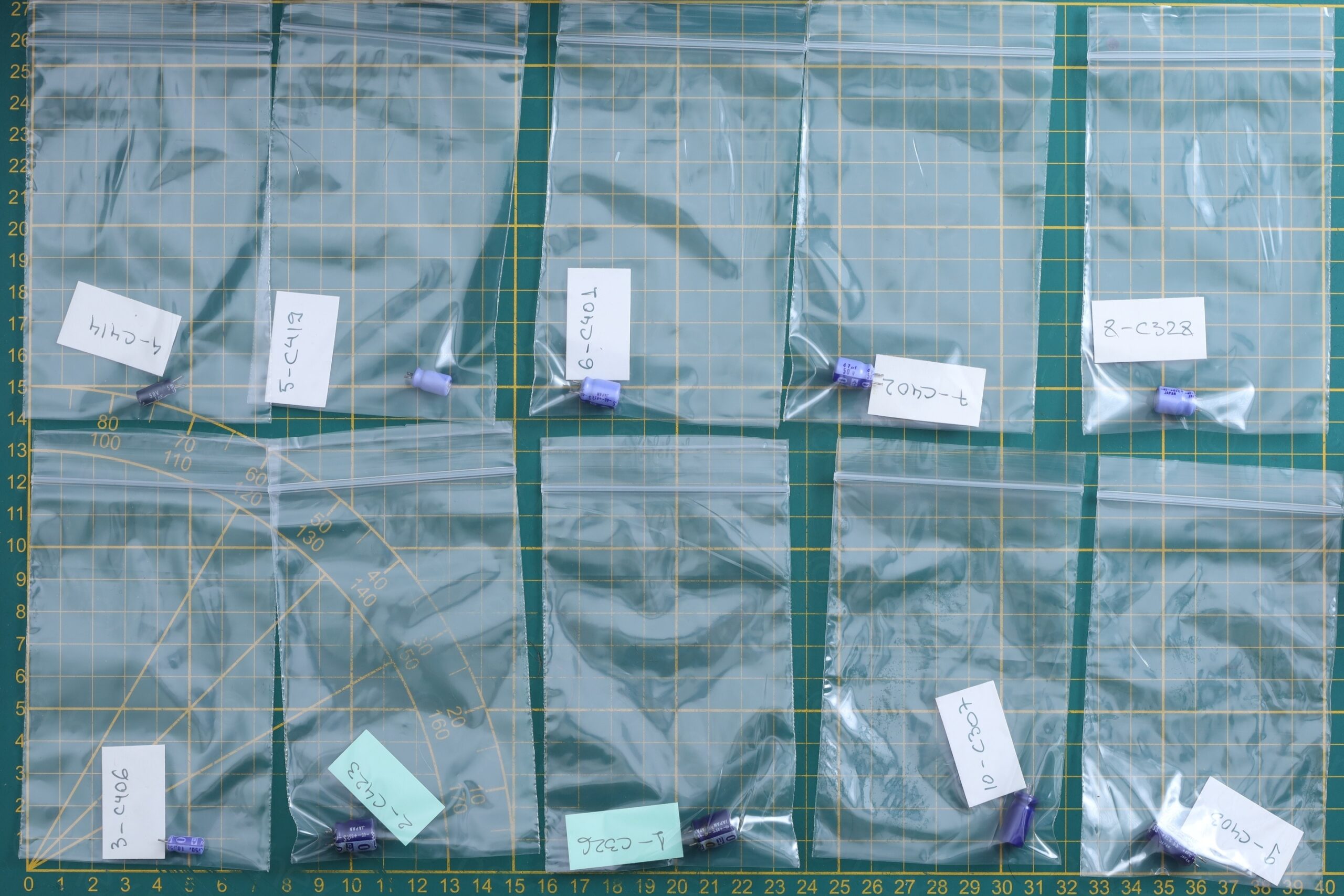
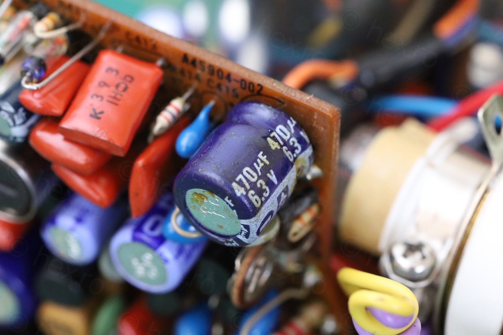
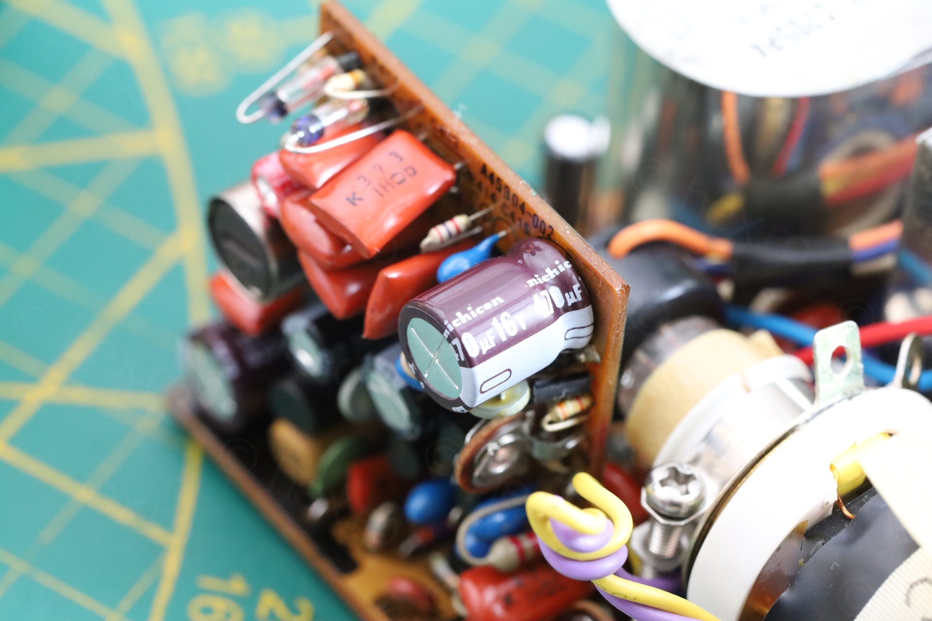
I initially hoped that replacing capacitors would fix the problem. I ended up replacing all the electrolytic ones on the deflection board as well as those around the CRT. I even took the time to swap them one by one, checking afterwards, but no improvements.


Oscilloscope measures
Except Test Point 9, they all look identical to the ones in the service manual.
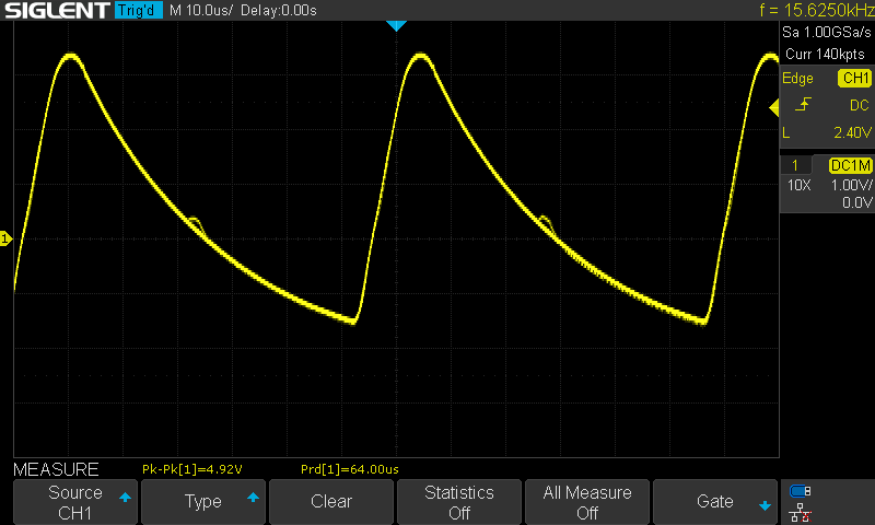
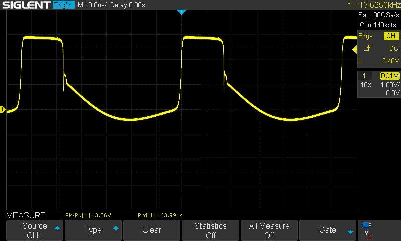
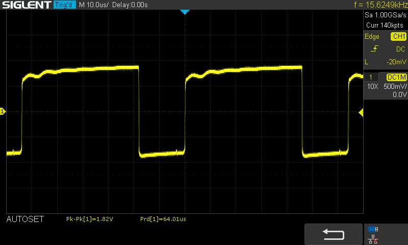
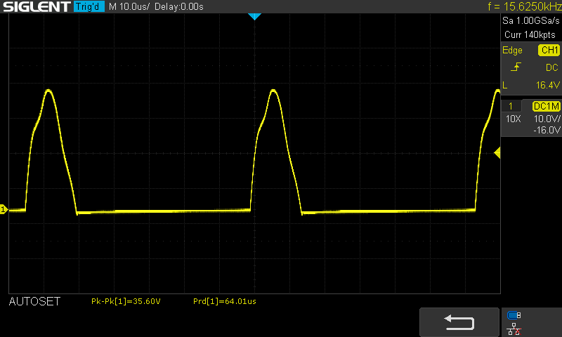
The manual shows these wave-forms:
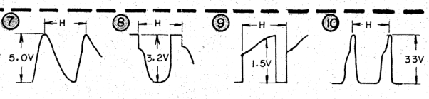
The problem is with Test Point 9, where the manual shows the waveform with almost 45 degree rising, but it is flatter (and with ringing), in the real TV.
I was now at a loss, and contemplating buying a second JVC that at least I’d have something to compare mine with.
Centering rings
I’ve also tried adjusting the centering rings on the neck of the CRT, but very little changed. It was just moving the ‘distorted’ image around, instead of reducing the horizontal spread on the left side of the CRT.
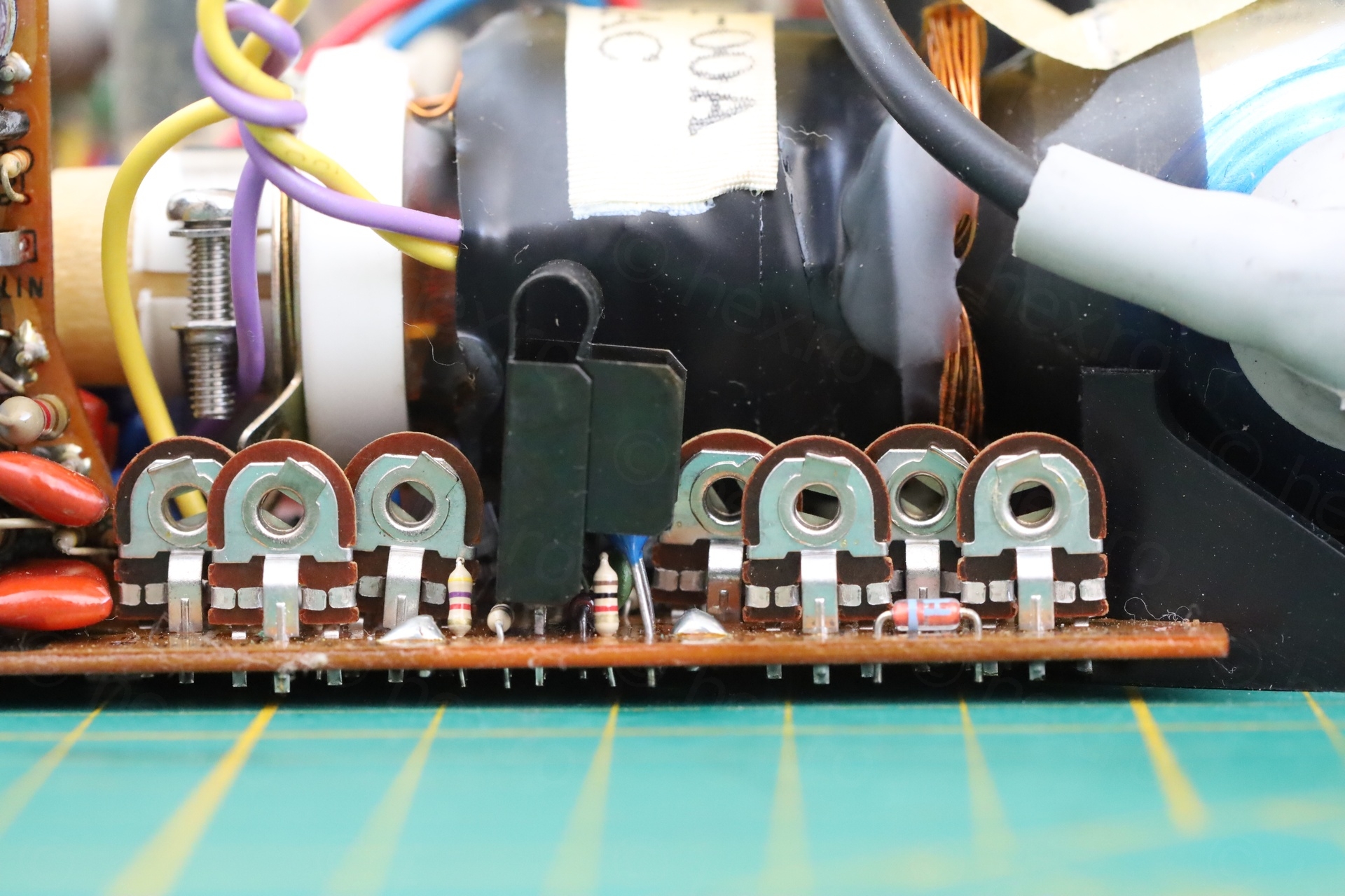
L401
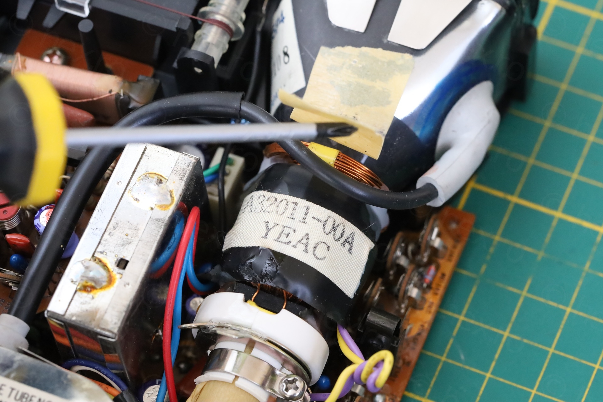
The only thing that seem to make a big difference was to adjust the L401 Horizontal Hold inductor:
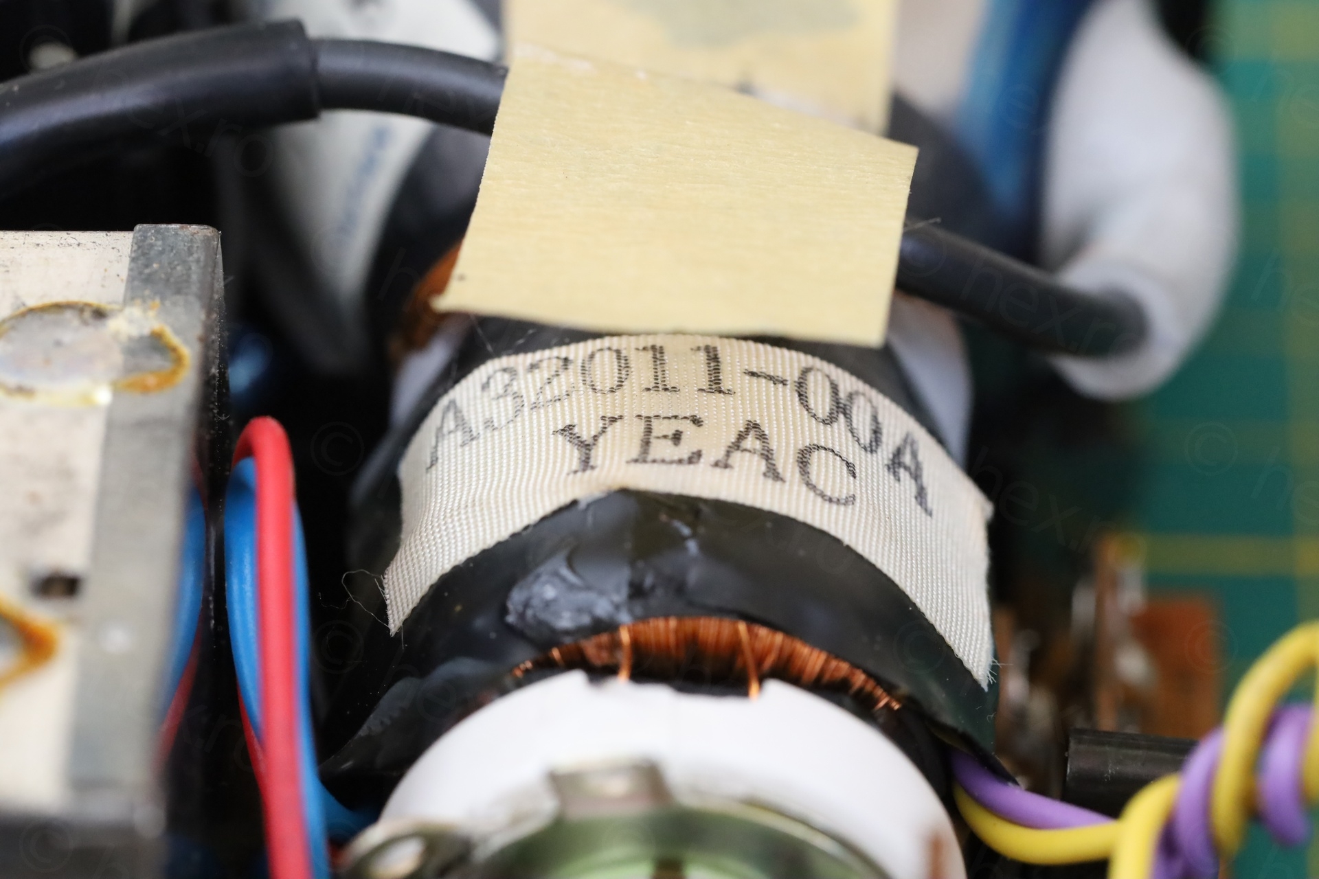
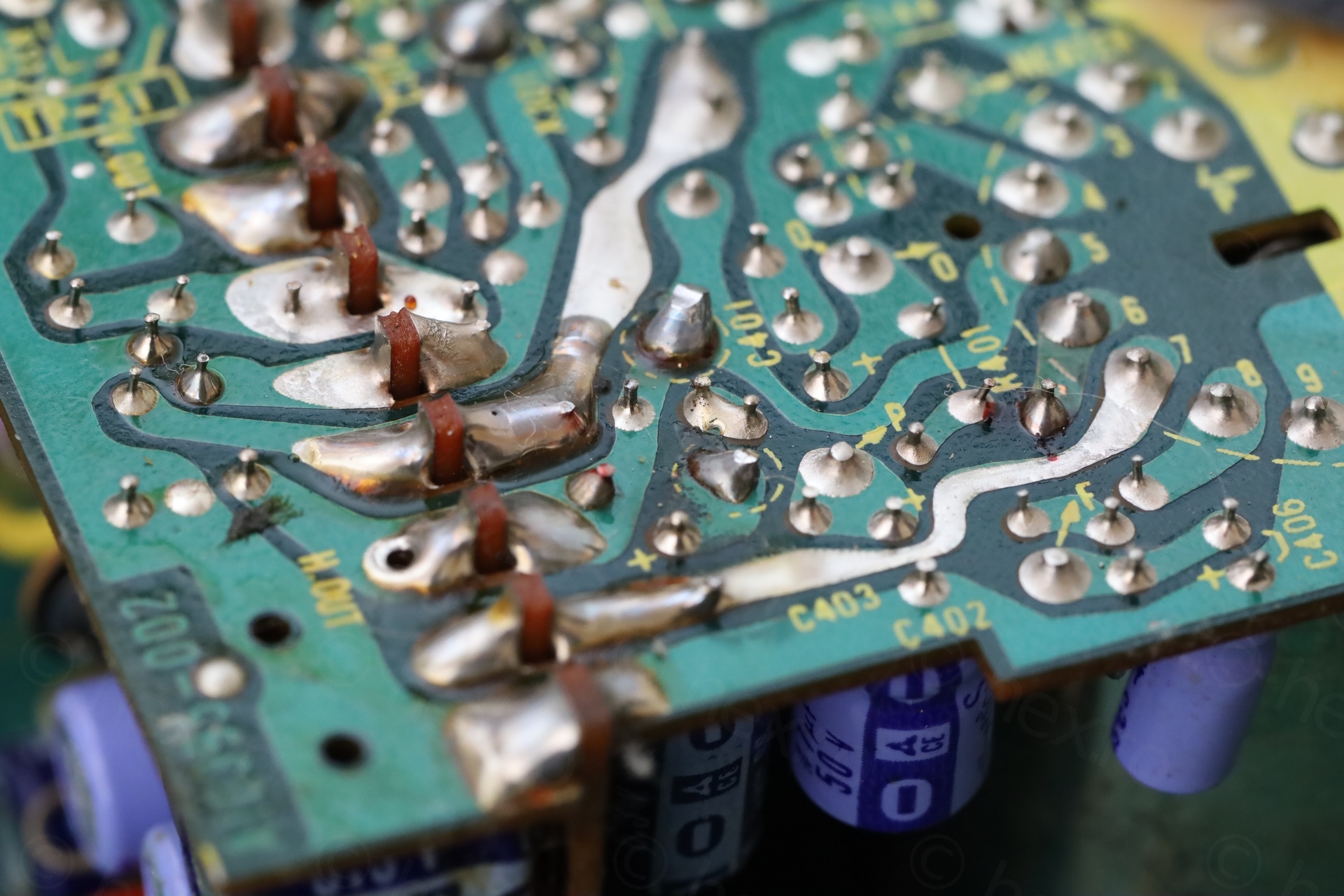
It is this inductor:
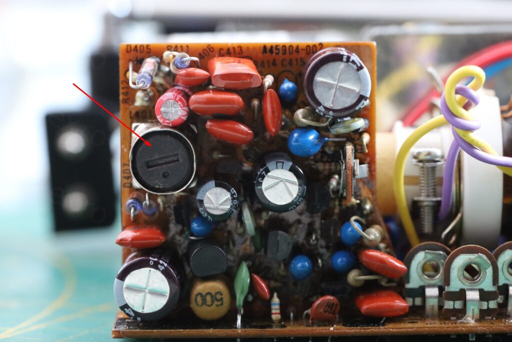
This got me even more confused. It seems that out of everything I tried, L401 makes a huge difference in bringing the left side image inwards. This doesn’t fix the distortion, it just brings the left side inwards. The round image still looks like an egg.
Thus, I don’t know how to fix it. I feel like adjusting the Horizontal Hold just makes the problem less worse, instead of fixing it.
Are they all like this ?
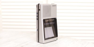
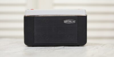
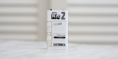
I could not find many photos with the TV showing some kind of test pattern, but thankfully, I was able to find 2:
And one more on a different website:
I am thankful for the authors above that took the time to hook a signal generator to the TV. Those two also exhibit the same style of both horizontal and vertical compression issues. It would be hard to generalize from N=3 samples, but I can’t stop wondering: Were all these JVC small TVs like this ? Or is it something that is going on them in time ? Unfortunately, I don’t have the experience / intuition to hone down in a specific area and try to debug. Nor a additional unit, to try to test individual core components, such as the yoke or the CRT itself.
One thing to mention – it looks like the schematic is similar to Sanyo TPM-2140 TV, but not the same. I do have a Broksonic TV CIRT-2097 which also exhibits horizontal linearity issues on the left side. Not sure if the schematics are different (I found some schematics for Nordmende TR 101 TV, which looks similar to the Broksonic, but this doesn’t necessarily mean they are the same inside).
Miscellaneous
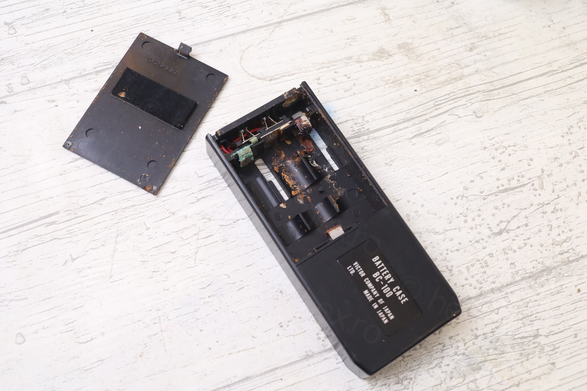
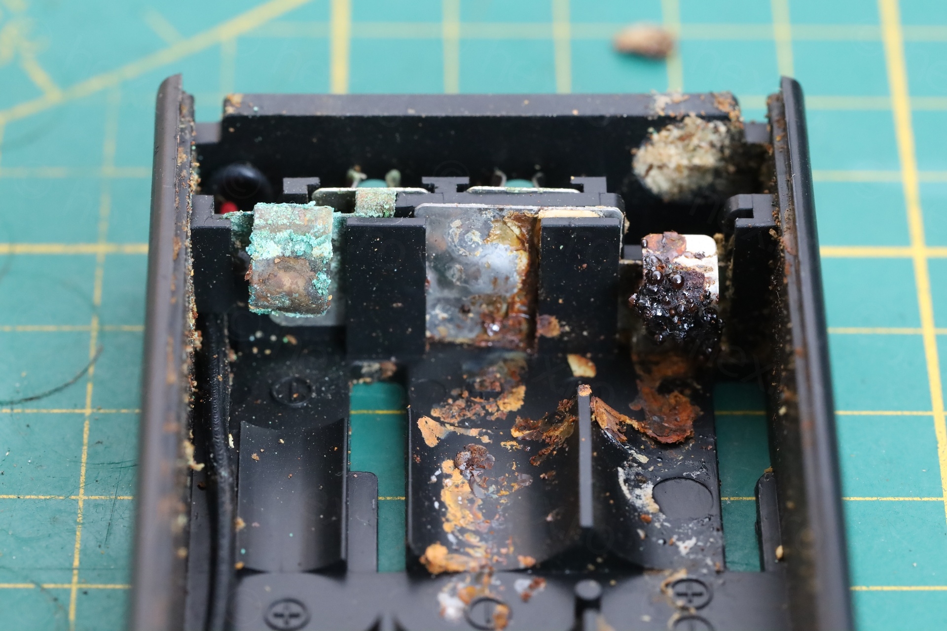
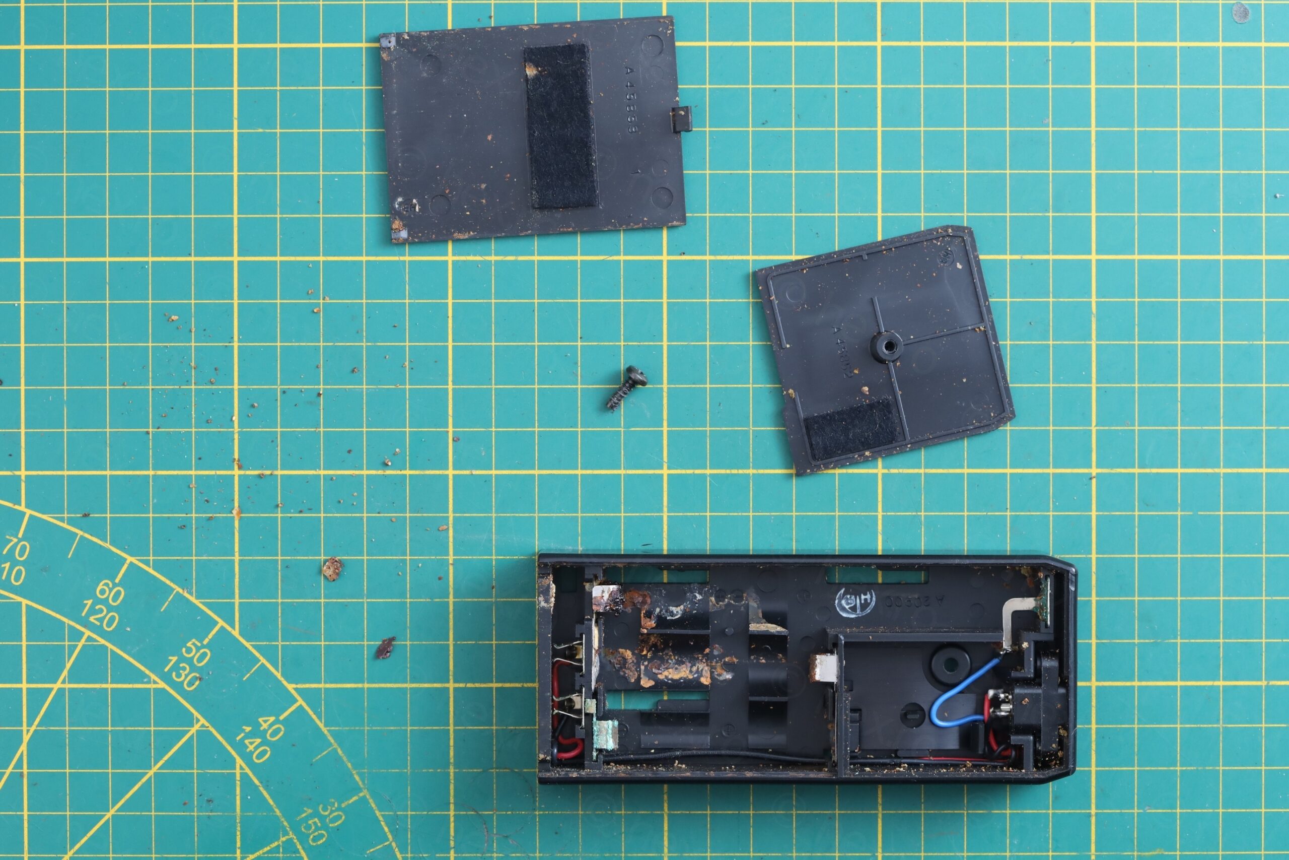
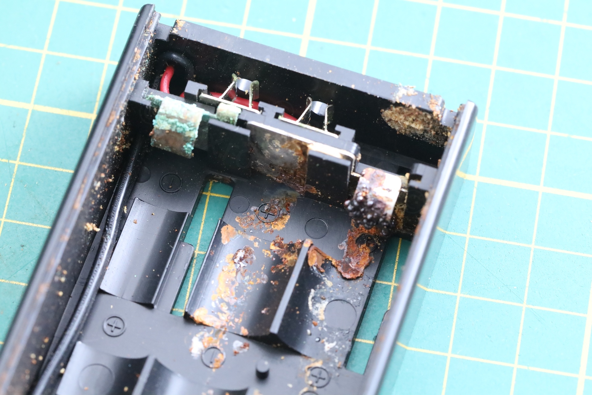
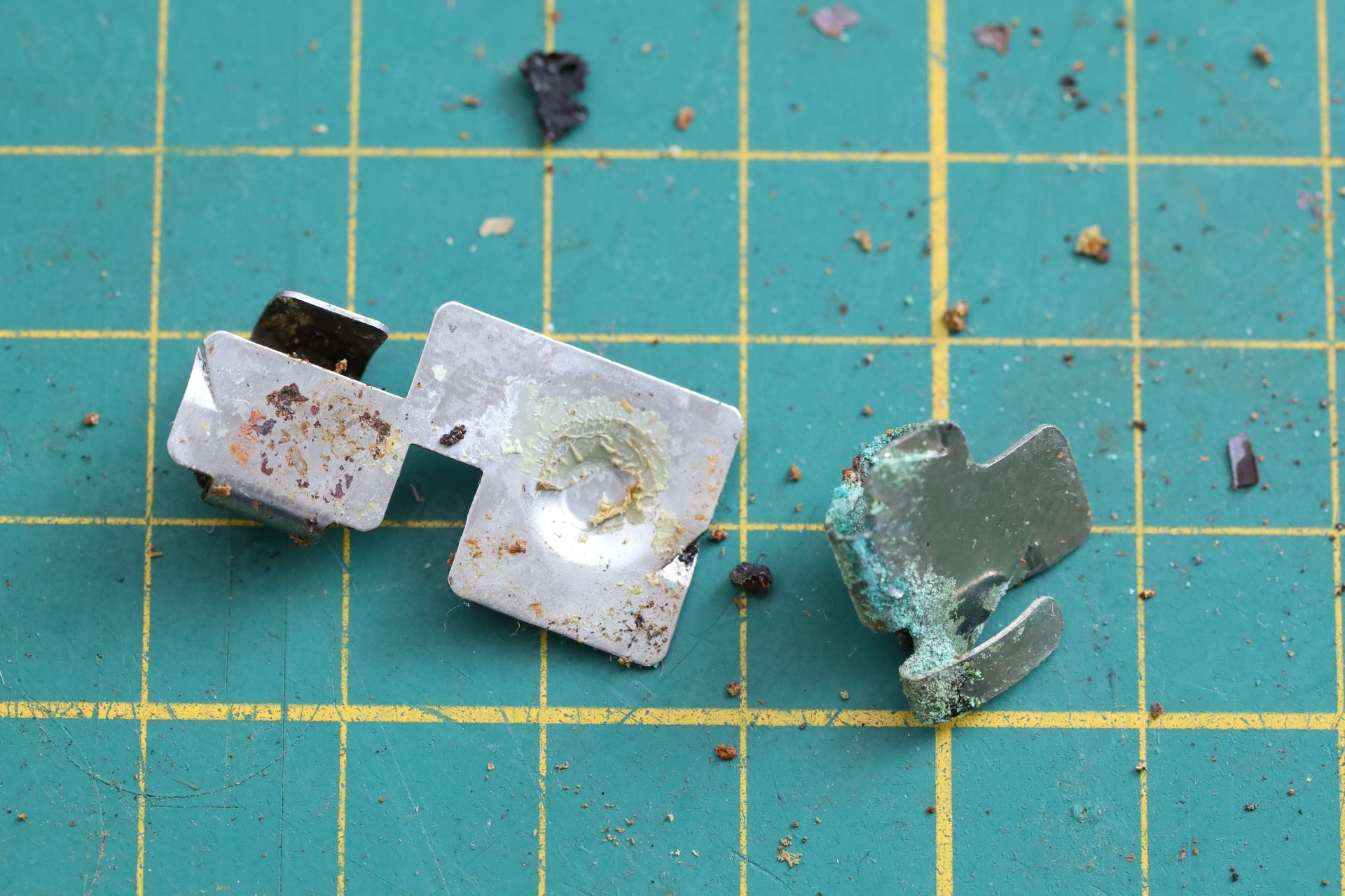
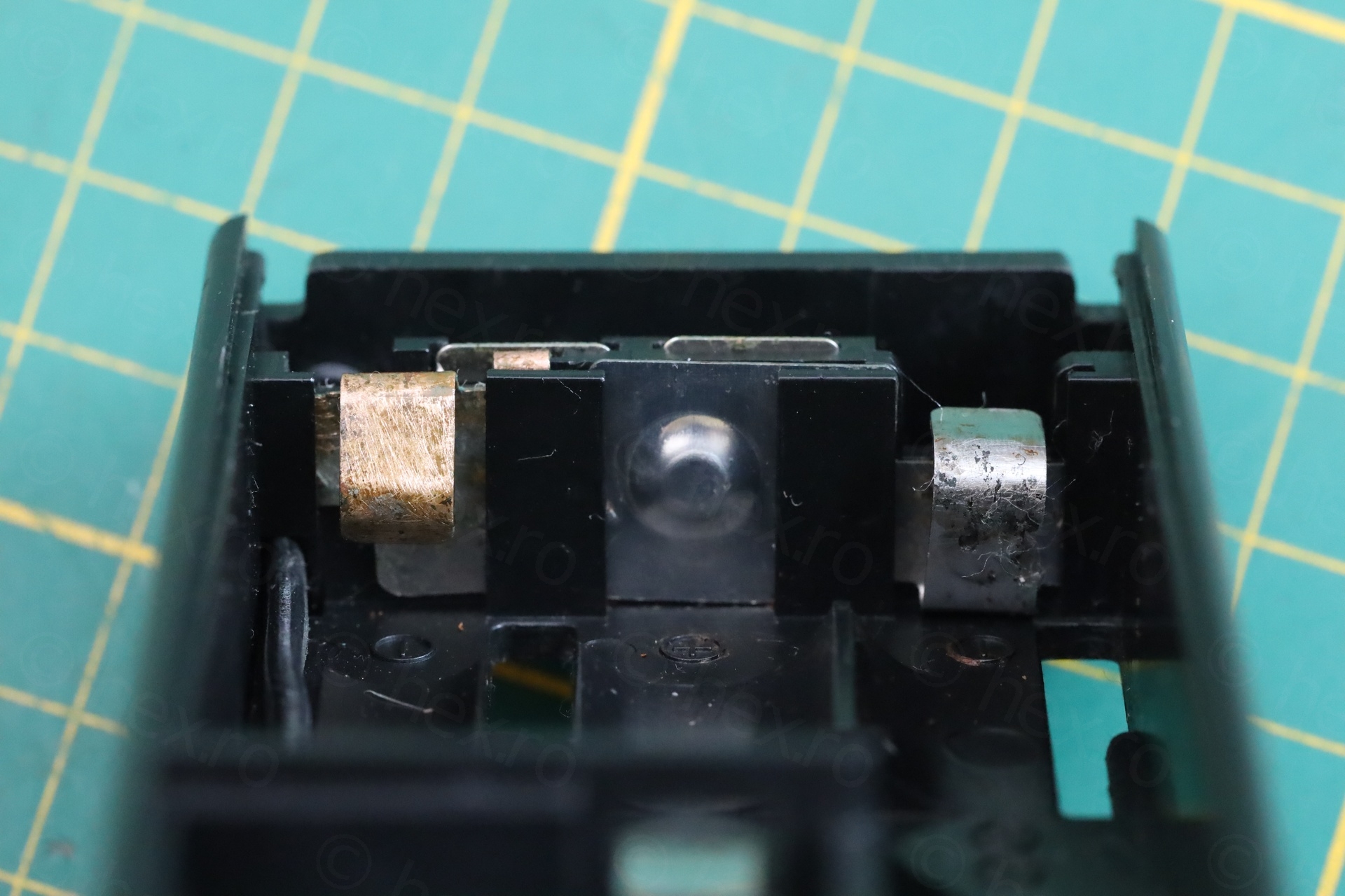
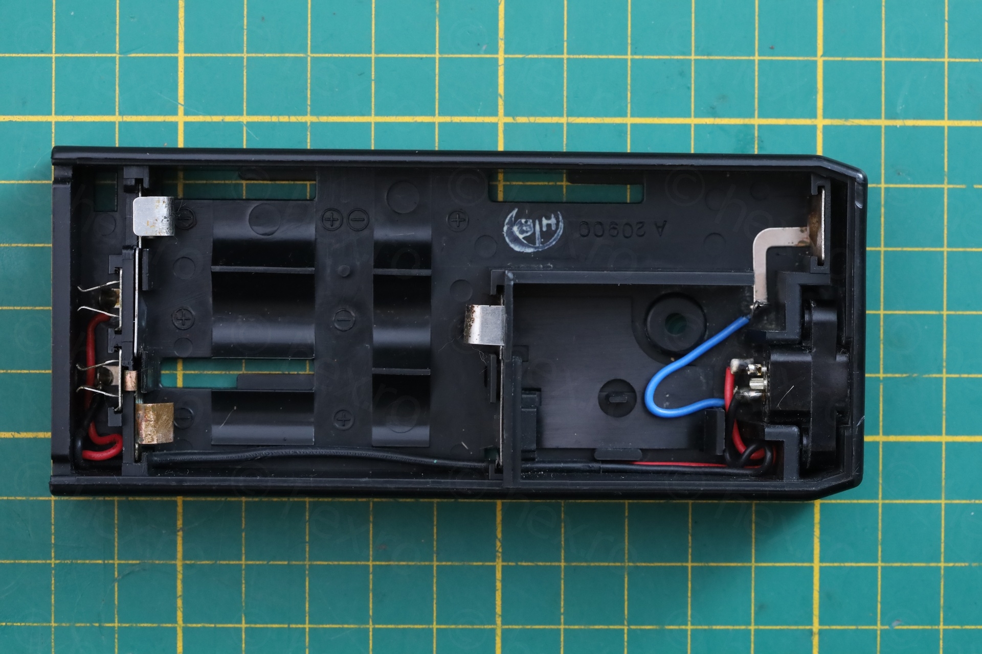
Cleaning up corrosion in battery compartment was tedious, but there was still plenty metal left so I used a grinding pen to take out the heavy deposits:
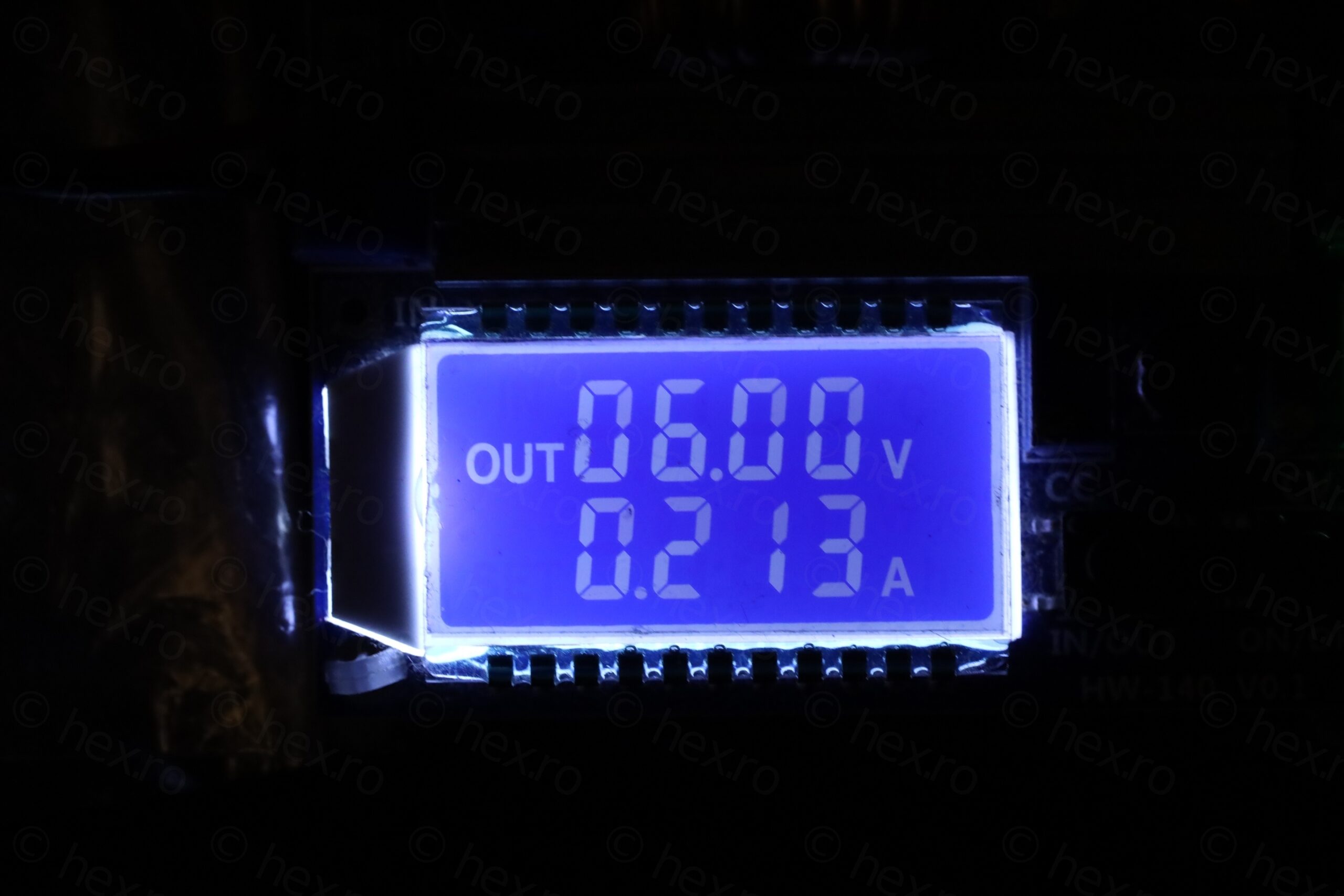
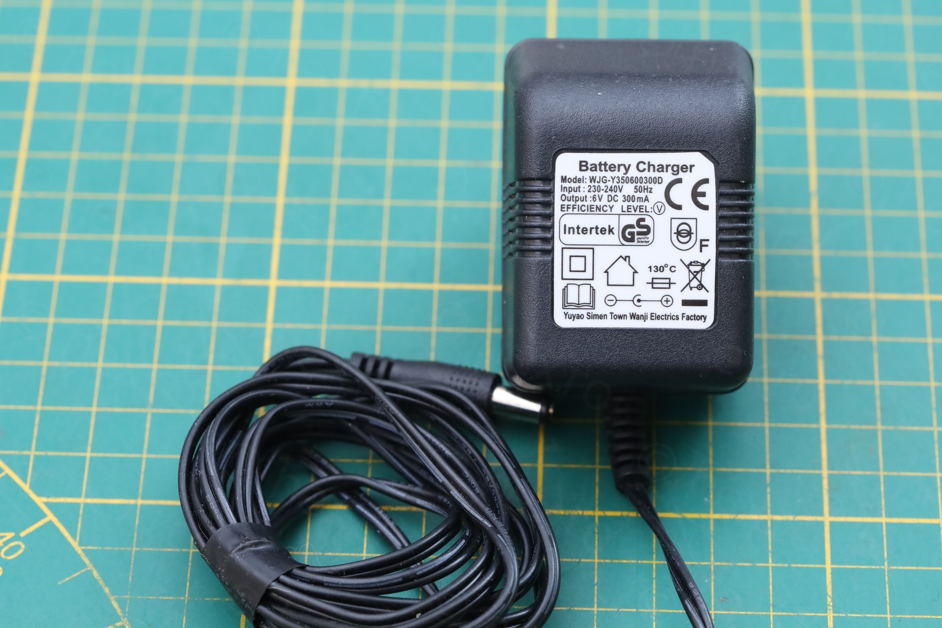
The TV is drawing about 220mA at 6V … and I managed to find a power plug of 300mA at 6V. However, I have already spent way too much time trying to sort things out, I gave up on designing and 3D printing a custom power plug:
Another thing I left unfixed was the UHF reception. It only seems to receive on VHF, I have tried two RF Signal Generators, and while they do produce correct UHF signals (tested with a separate TV), no reception on this one.
Conclusions
An interesting TV that got me studying Analog TV signals … I don’t understand yet, but first step was made 🙂
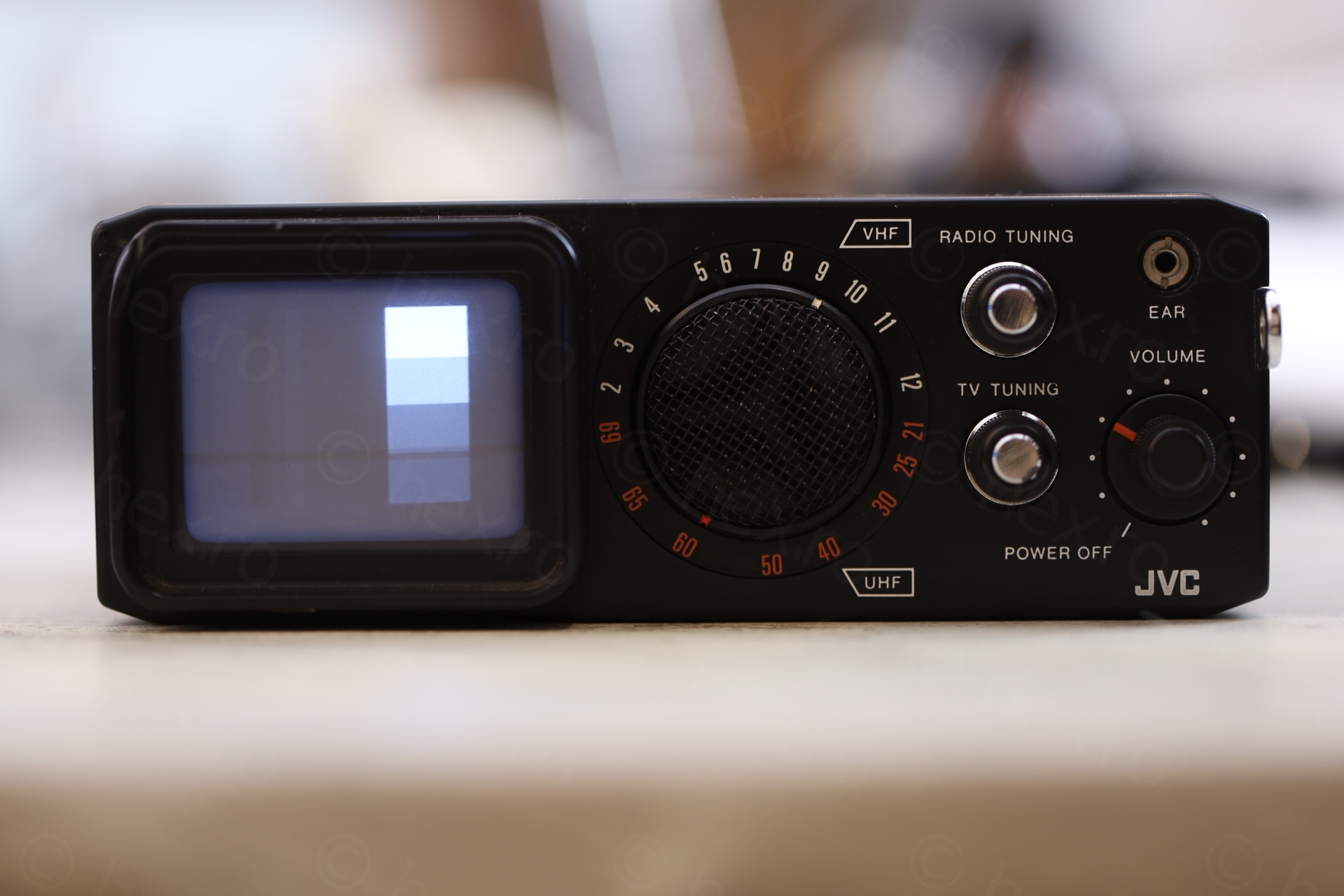
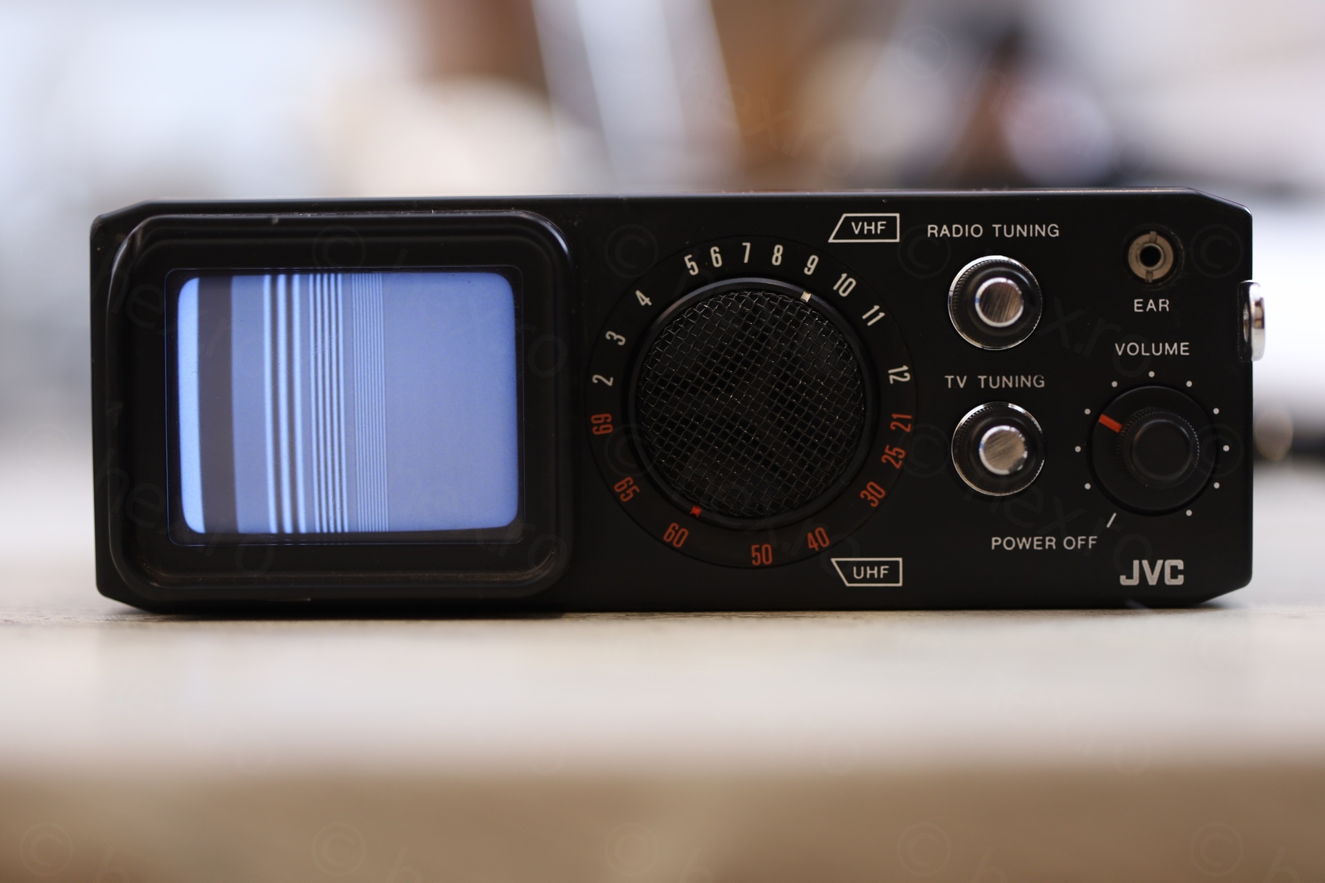
Few more shots with different test patterns:

Leave a Reply