

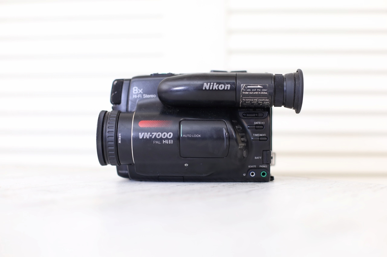
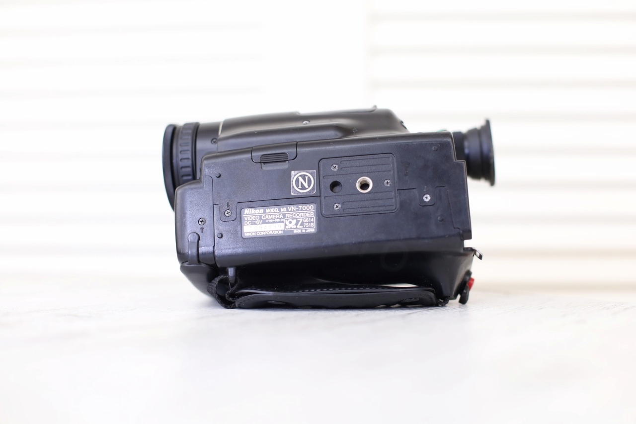
I found this CRT inside a Nikon VN-7000 Video Camera that I have bought recently from the flea market. I wasn’t looking to buy a camera, but this one was interesting, since I was convinced is a Sony. Looking closer, it was a Nikon! I don’t remember even taking a Nikon apart, and confused by my mistake, I decided to buy it.
Now that I took it apart, my confusion was justified. It is identical to the Sony CCD-TR705E, down to the exact model of the CRT.
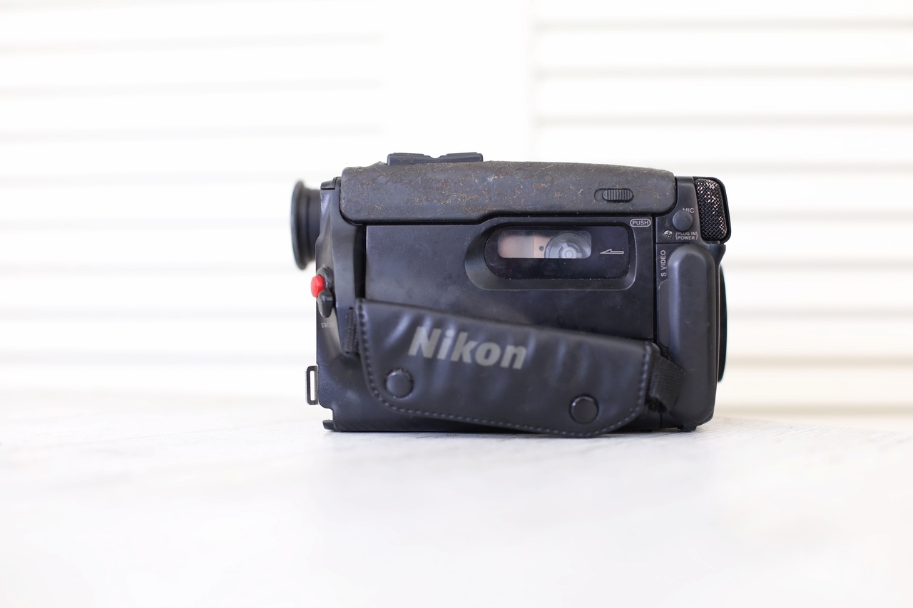
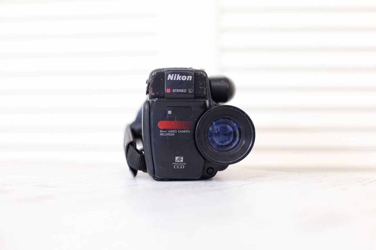
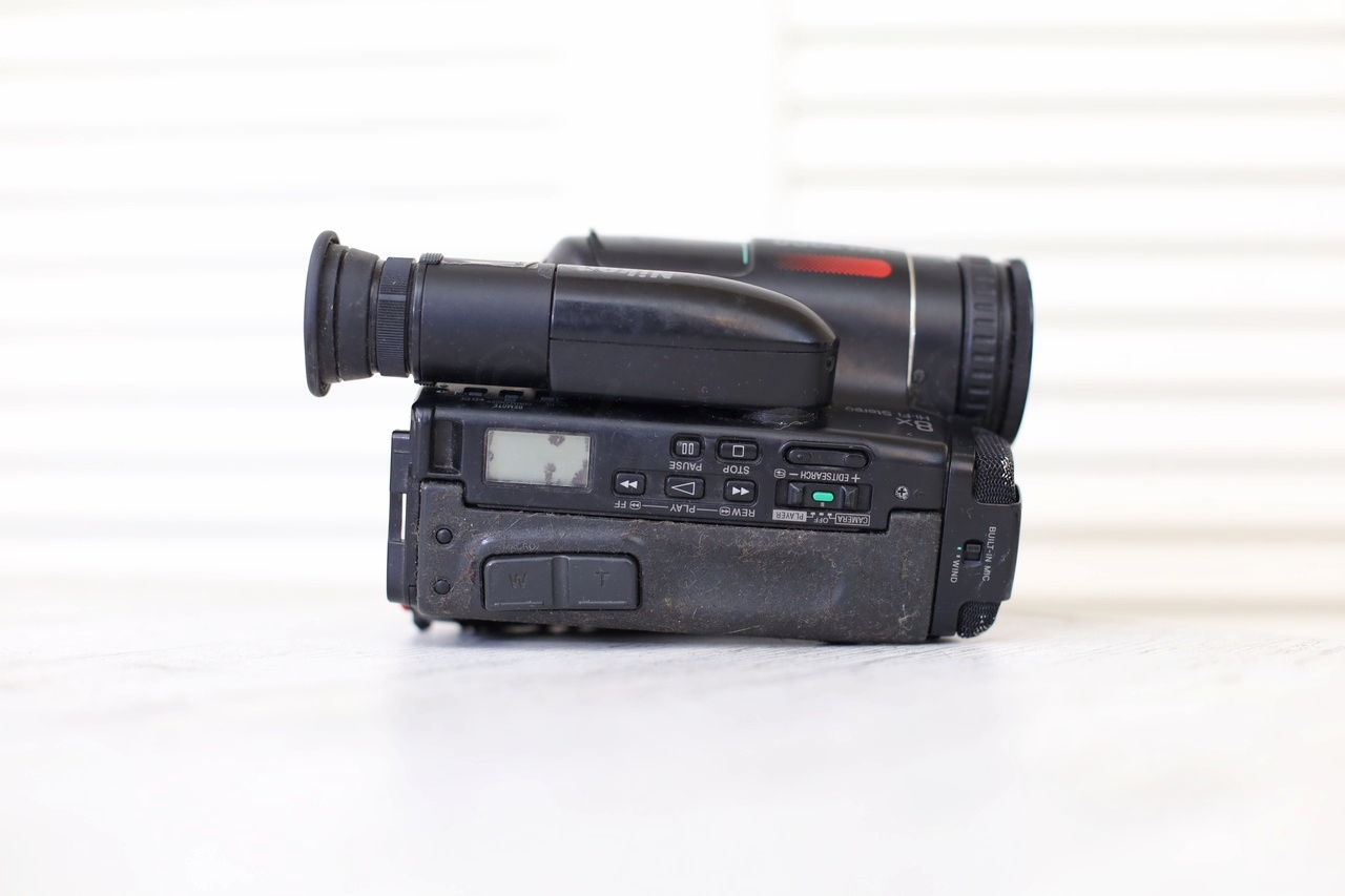
Camera overview
Camera looks clean with no traces of battery corrosion. And just like the Sony, the top plastic started deteriorating – but at least it was not so sticky.
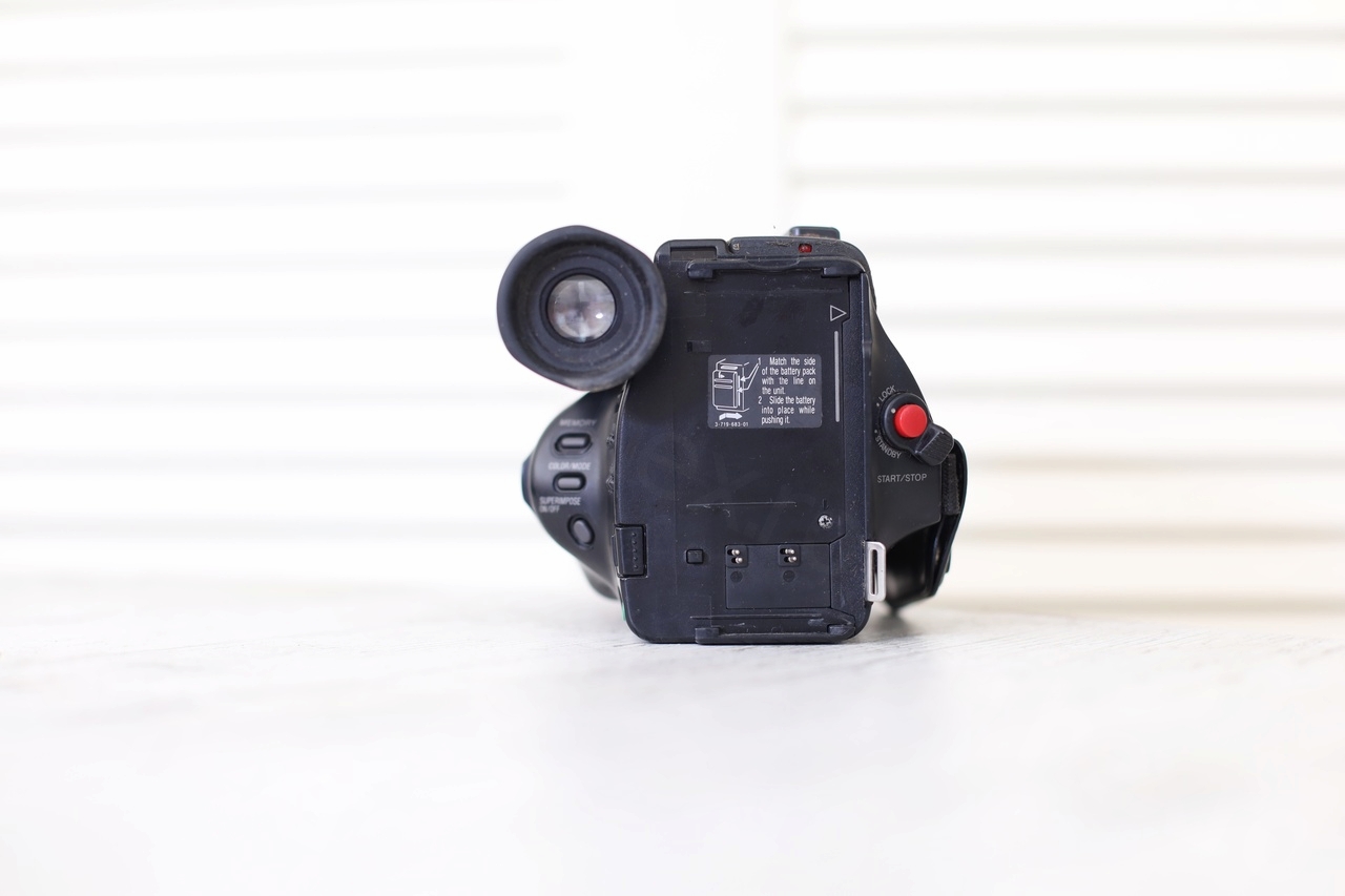
I’ve tried to power it on with a current limited power supply, but it would just flash the screen and go dead again.
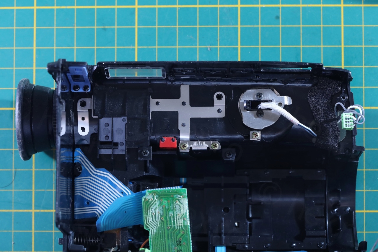
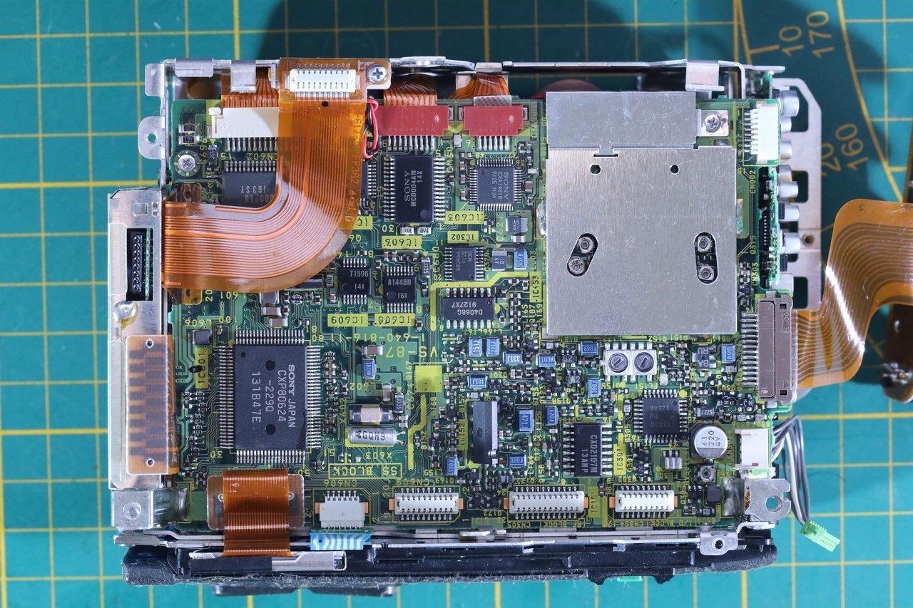
Opening up
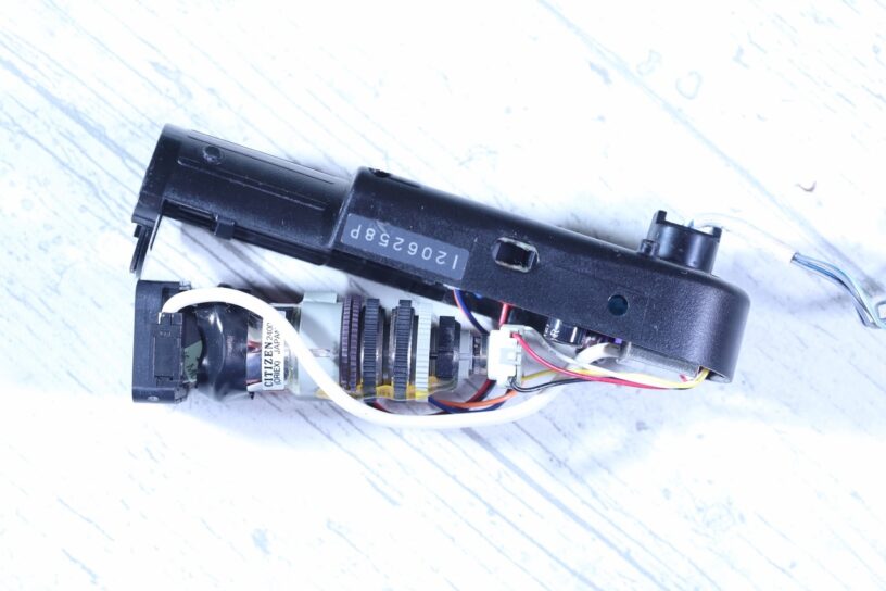
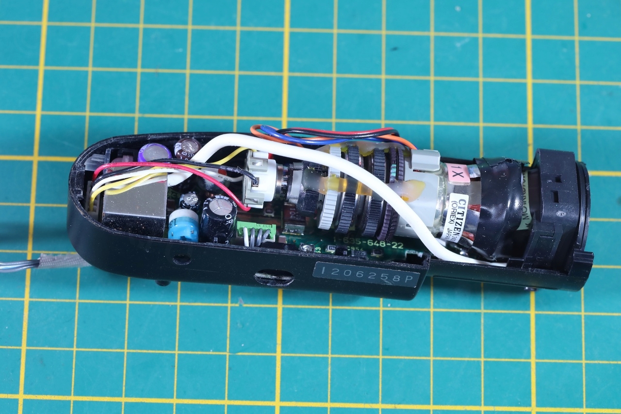
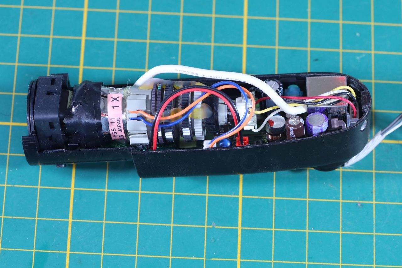
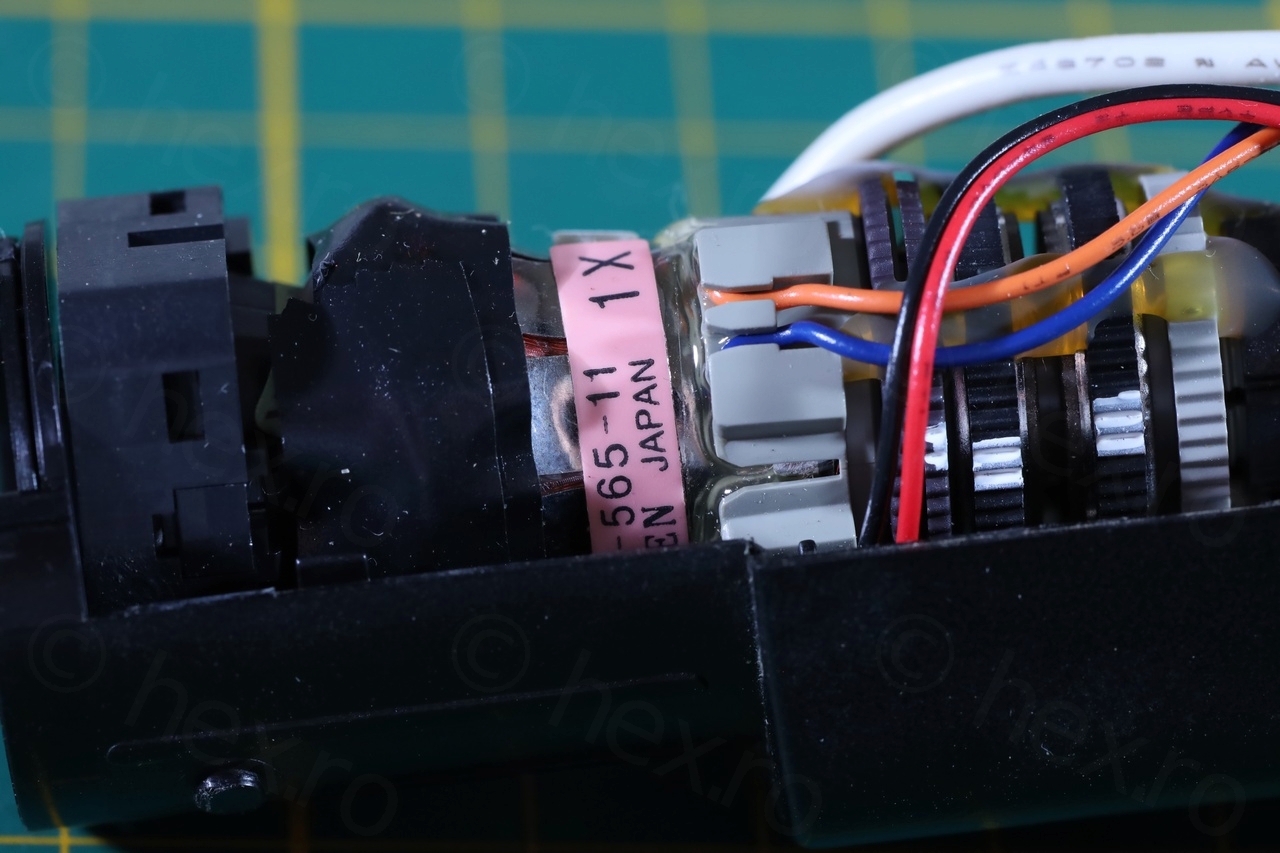
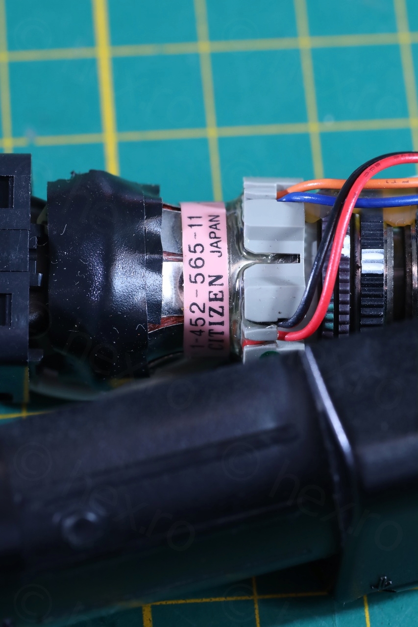
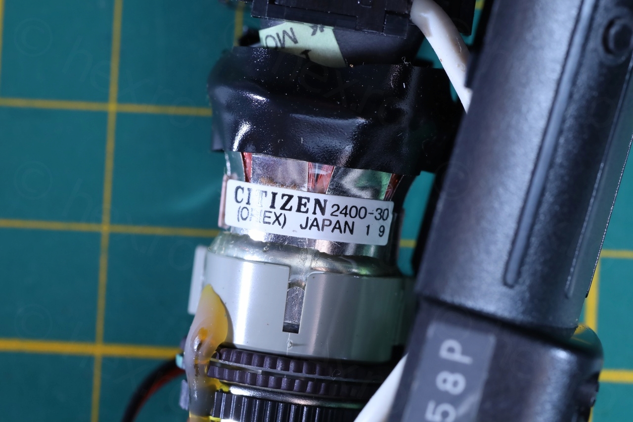
Opening up was easy. Surprisingly I found no date codes stamped inside the plastic panels. I finally found one inside the Electronic Viewfinder.
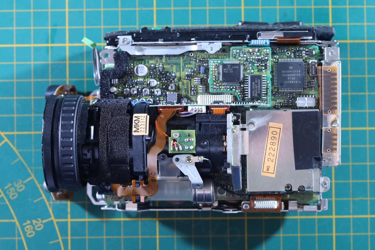
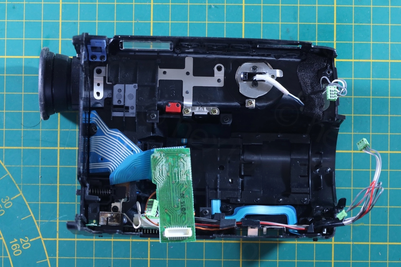
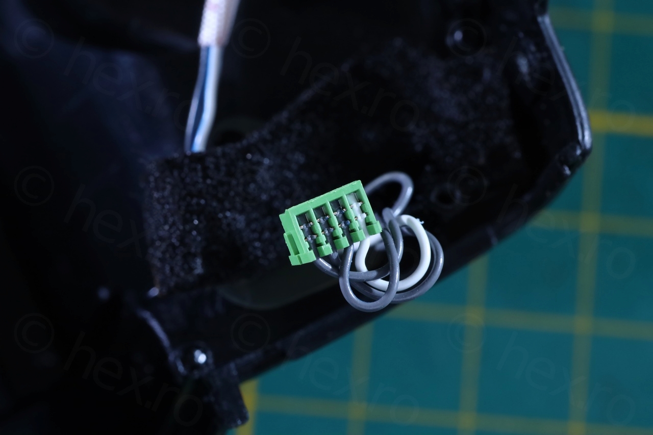


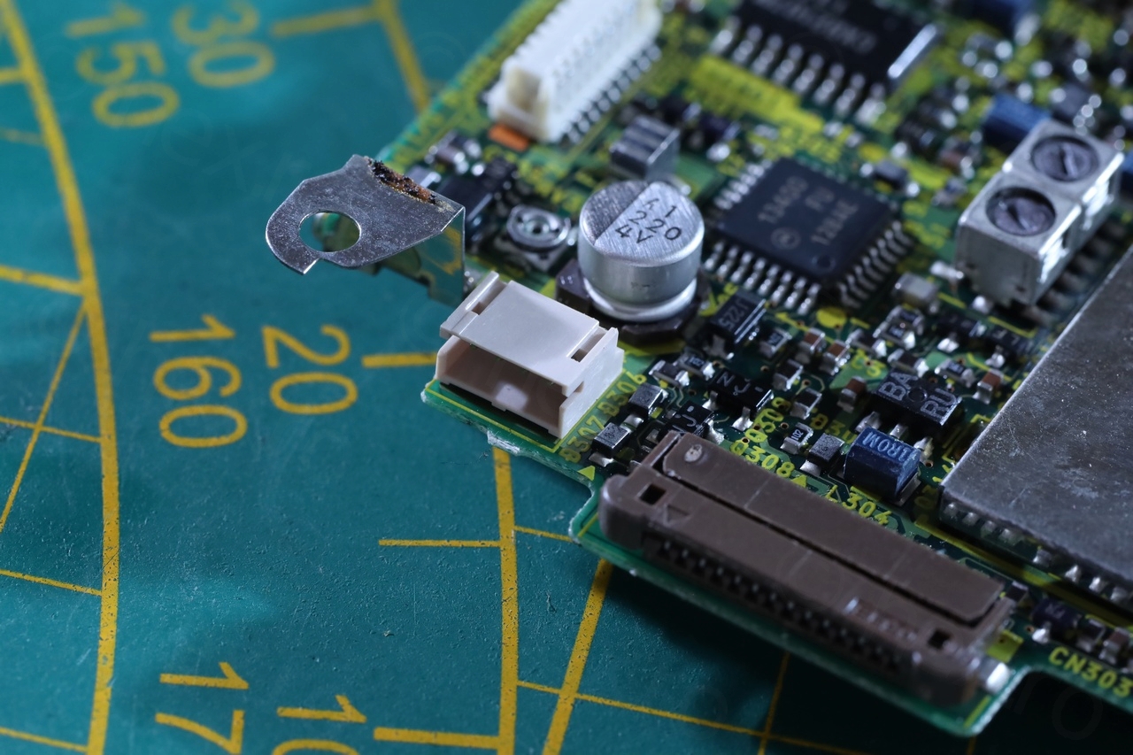
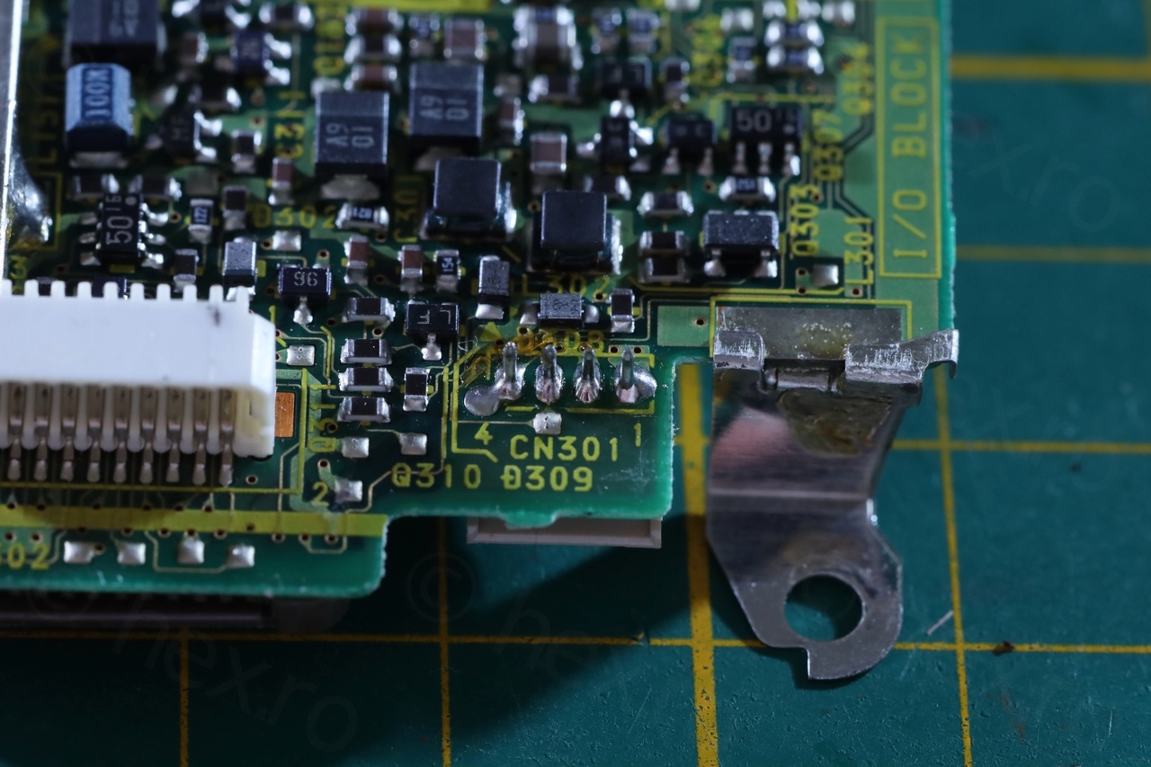
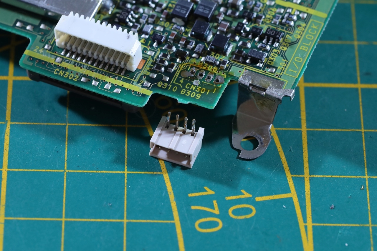
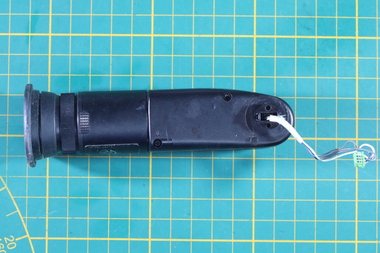
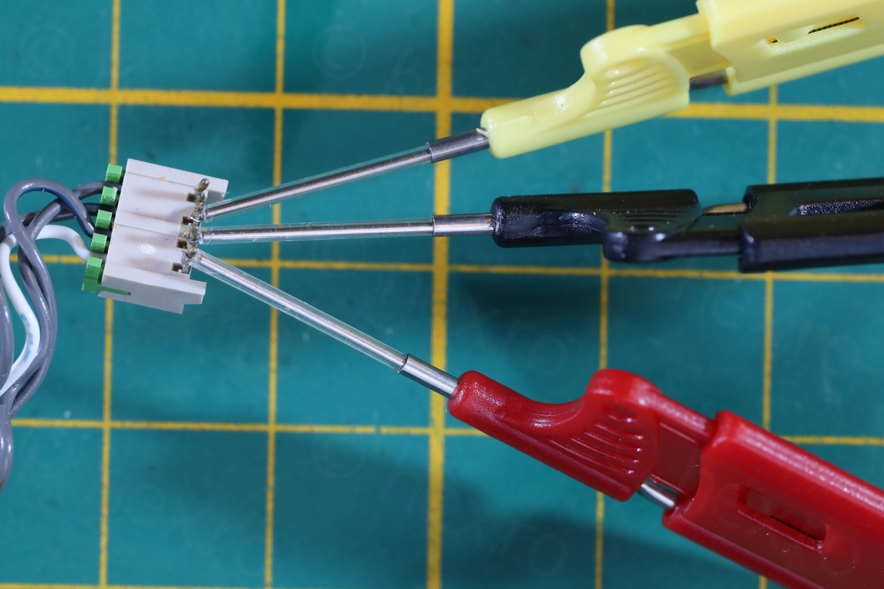
I had to also recuperate the little plug where the EVF connects to, so that I can provide the signals for it using some tiny clamps.
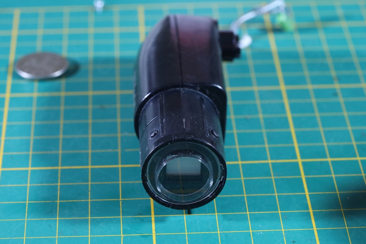
Electronic View Finder
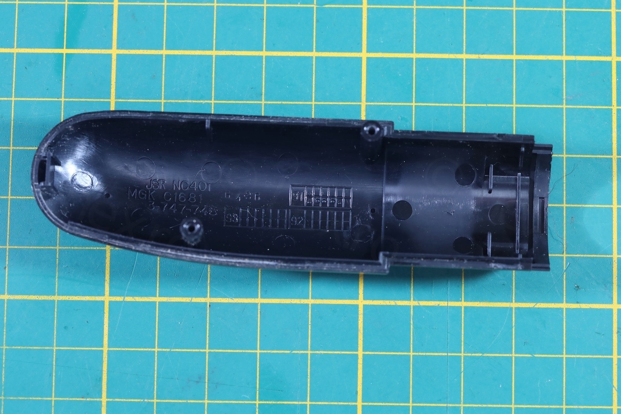
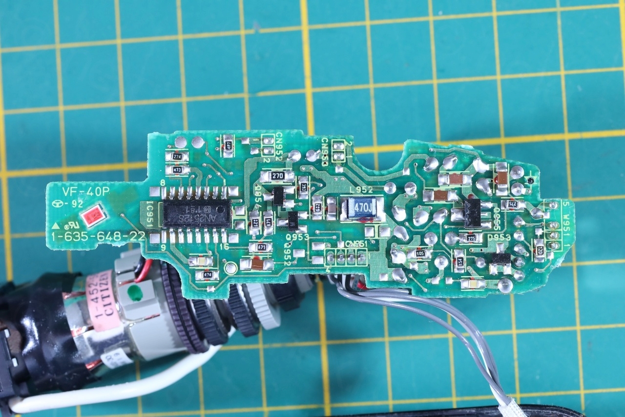
This was more tricky to take apart since even if it only has two screws, it is closed very tightly. I finally found a small gap where I could start to pry it off.

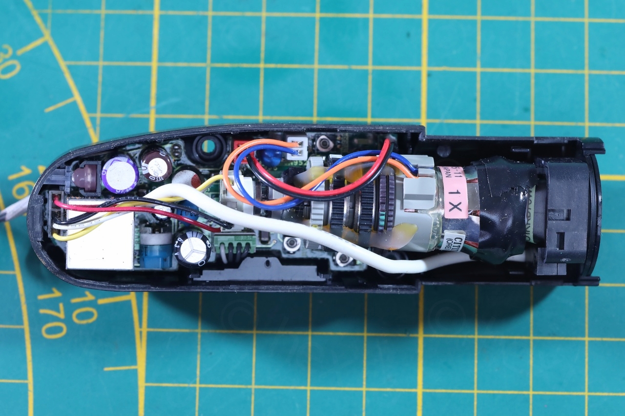
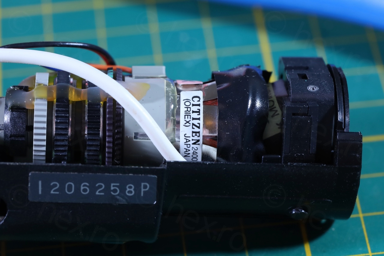
Unlike Sony, the capacitors here did not leak and were measuring small ESR values. I took the board out to find that the driver IC is an AN2512S:
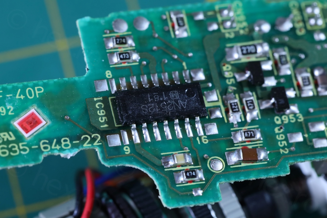
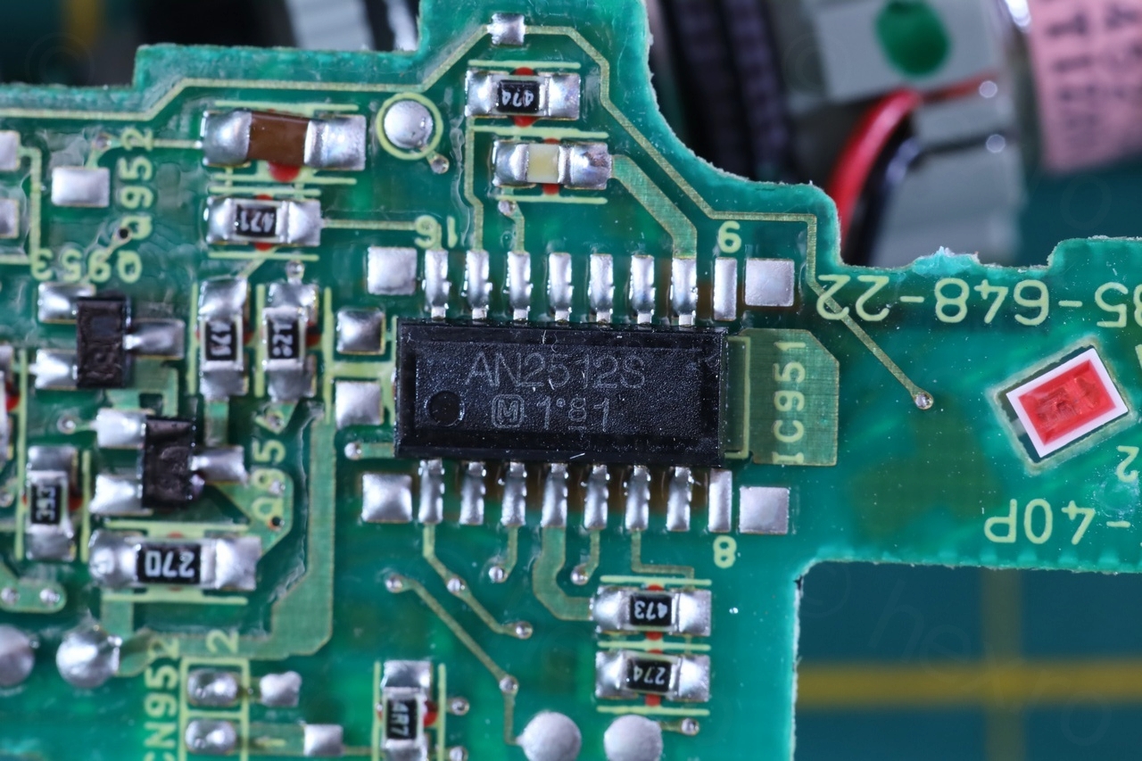
Identifying the signals was easy, the first Pin (white) beeped a bit when probing (which usually indicates VCC, as the filter capacitor is charging). Second pin had continuity to the external of the Flyback Transformer – so most likely GND. And third pin was Video IN. The 4th pin turns on the two recording LEDs.
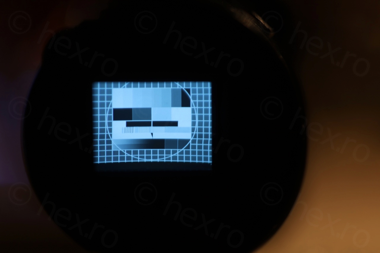
While the CRT has plenty brightness – the image is slightly shifted upwards, hiding the top bar of the Raspberry PI Desktop. The 4 potentiometers on the driver board do not seem to have an impact on the Vertical Positioning, only on Vertical size ..

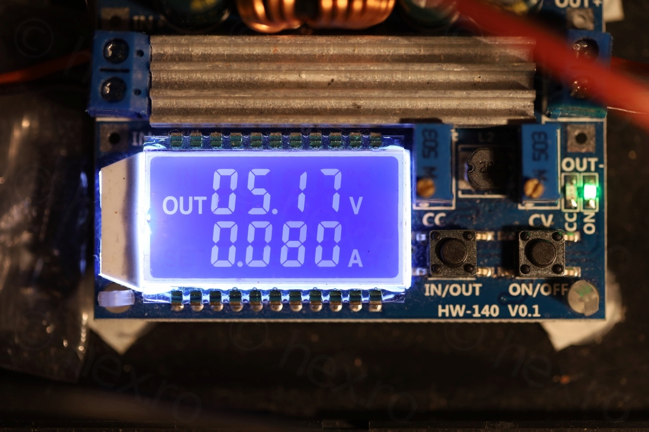

The sharpest image is around 5.17V where the device draws 80mA.
Leave a Reply