
A friend was walking through the Lille flea-market (La Braderie de Lille) and stumbled upon a small table full of old electronics gear. He proceeded to send me a photo, I prompt replied with a squiggly arrow pointing to this radio.
Table of Contents
Evaluation
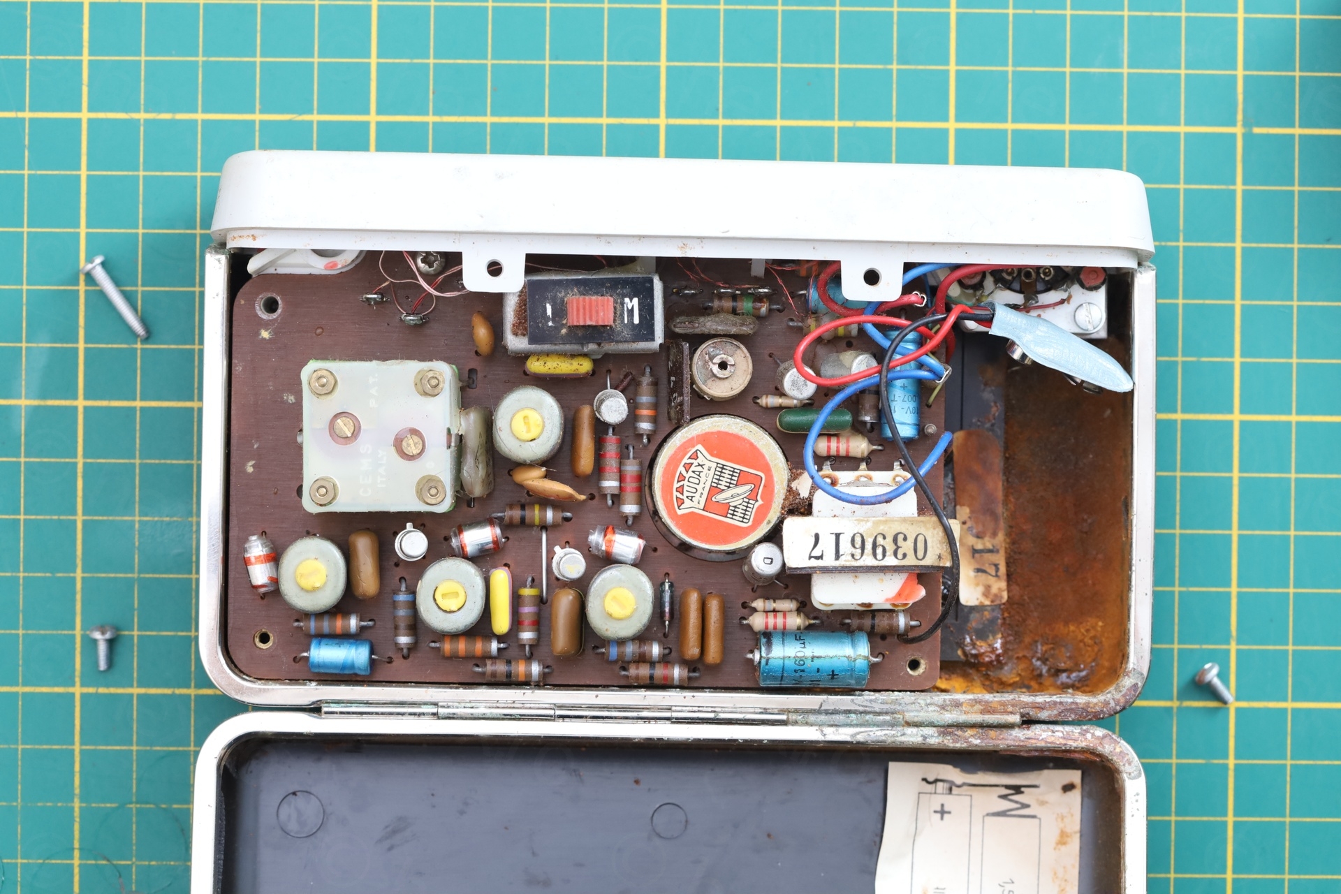
Taking the radio out of its housing left a rusty haze on my hands. Went to try the tuning knob, but soon realized…
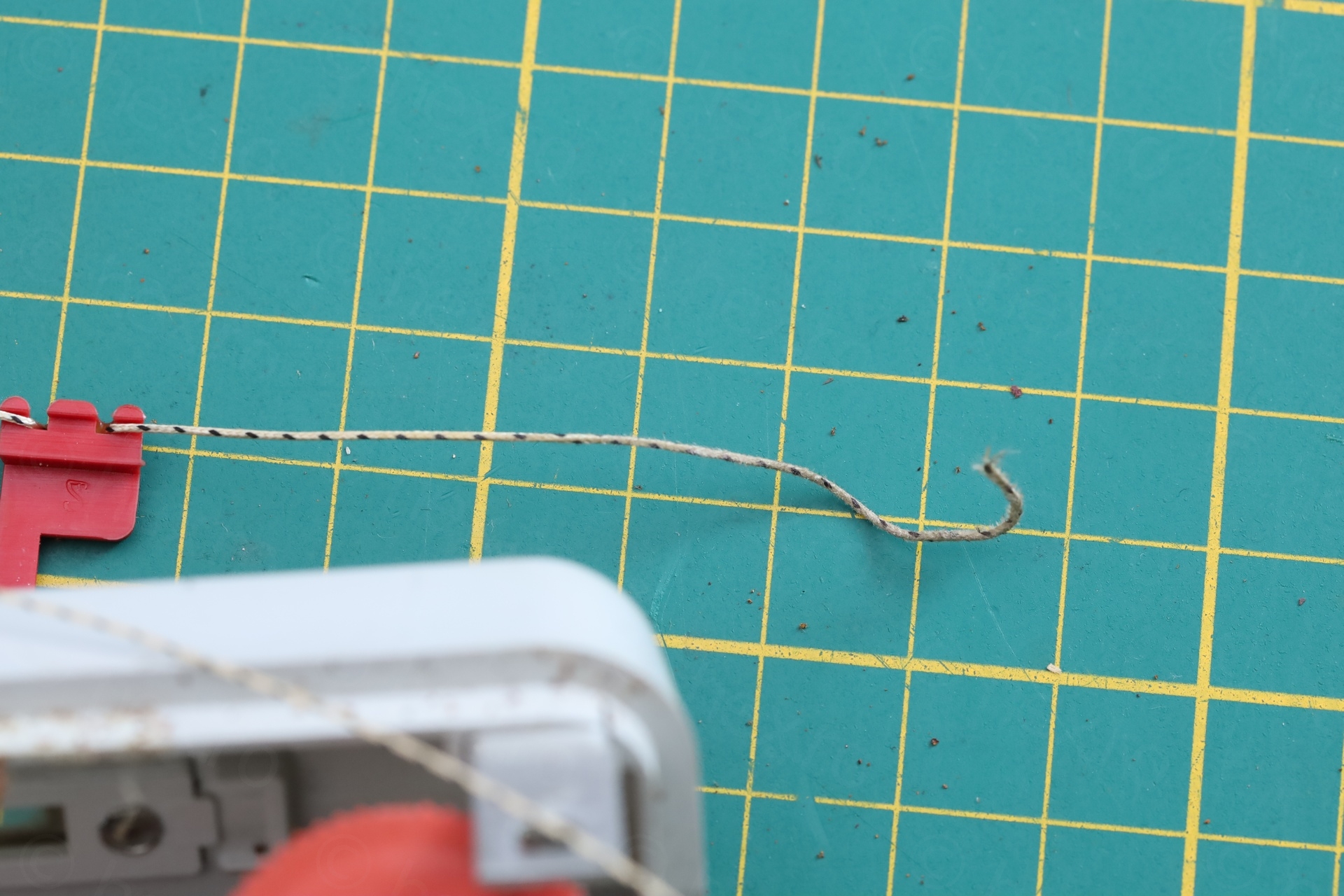
… the dial cord is snapped. Pffft.
Overview
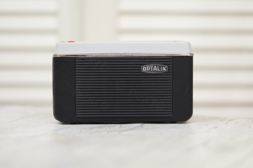
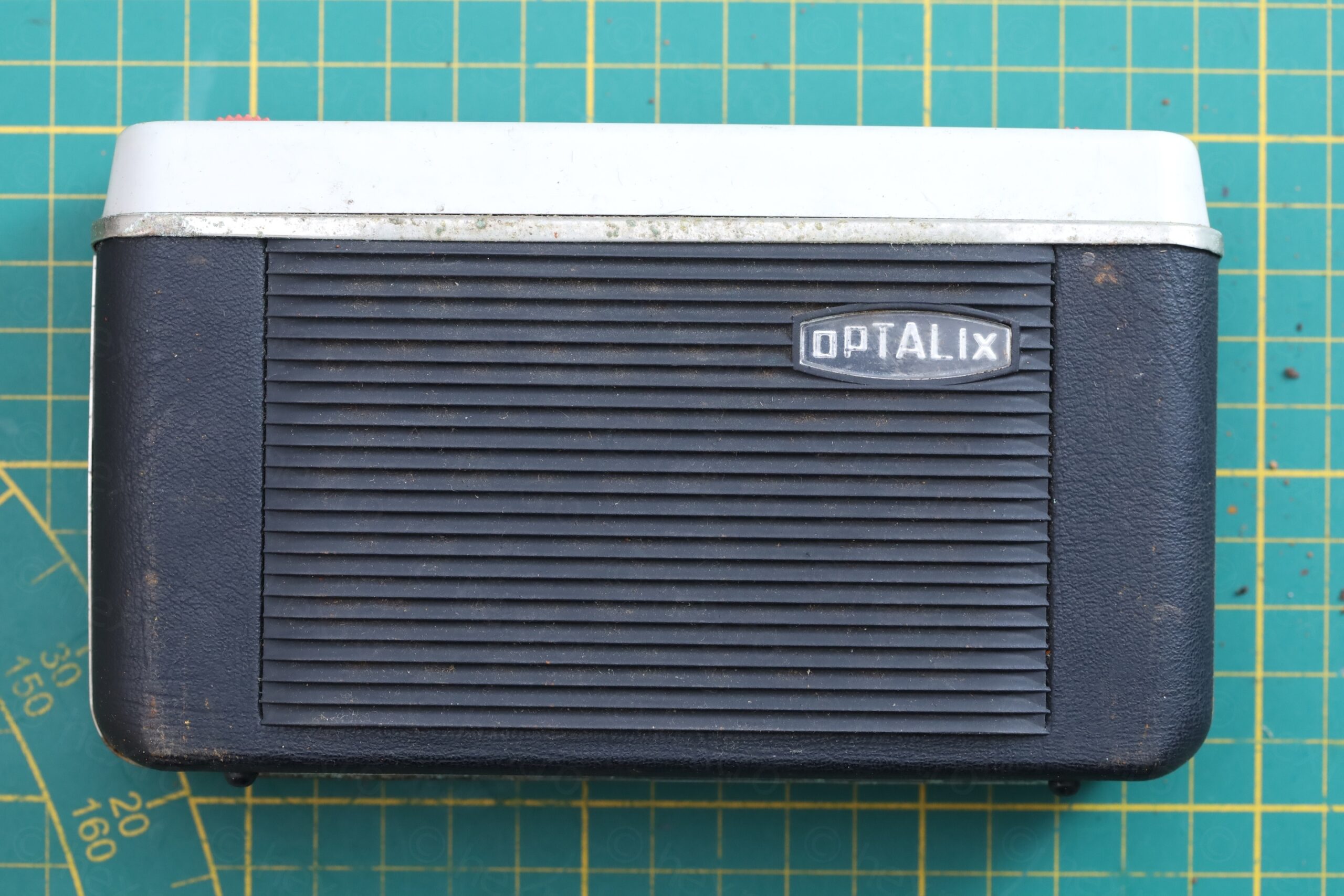
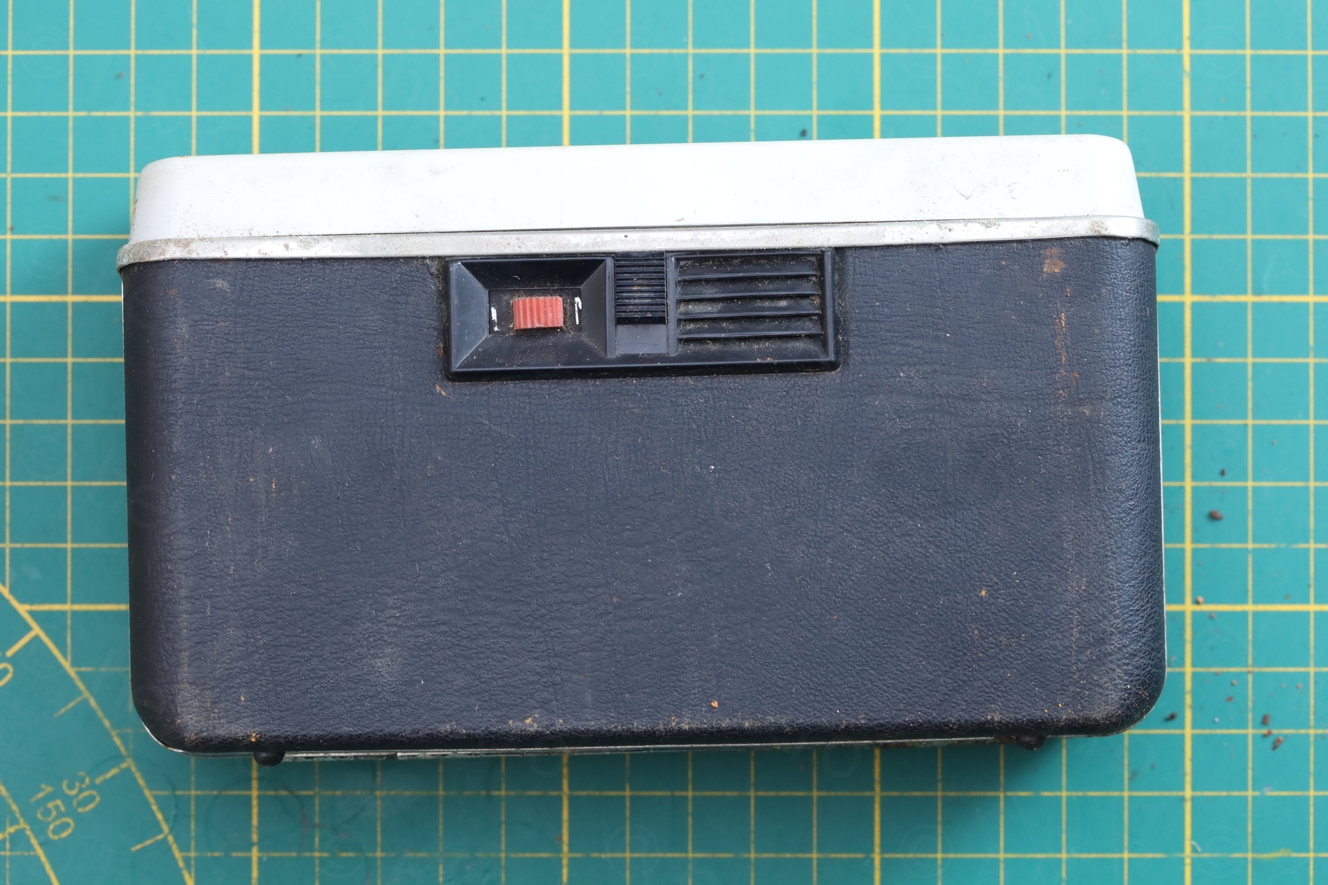
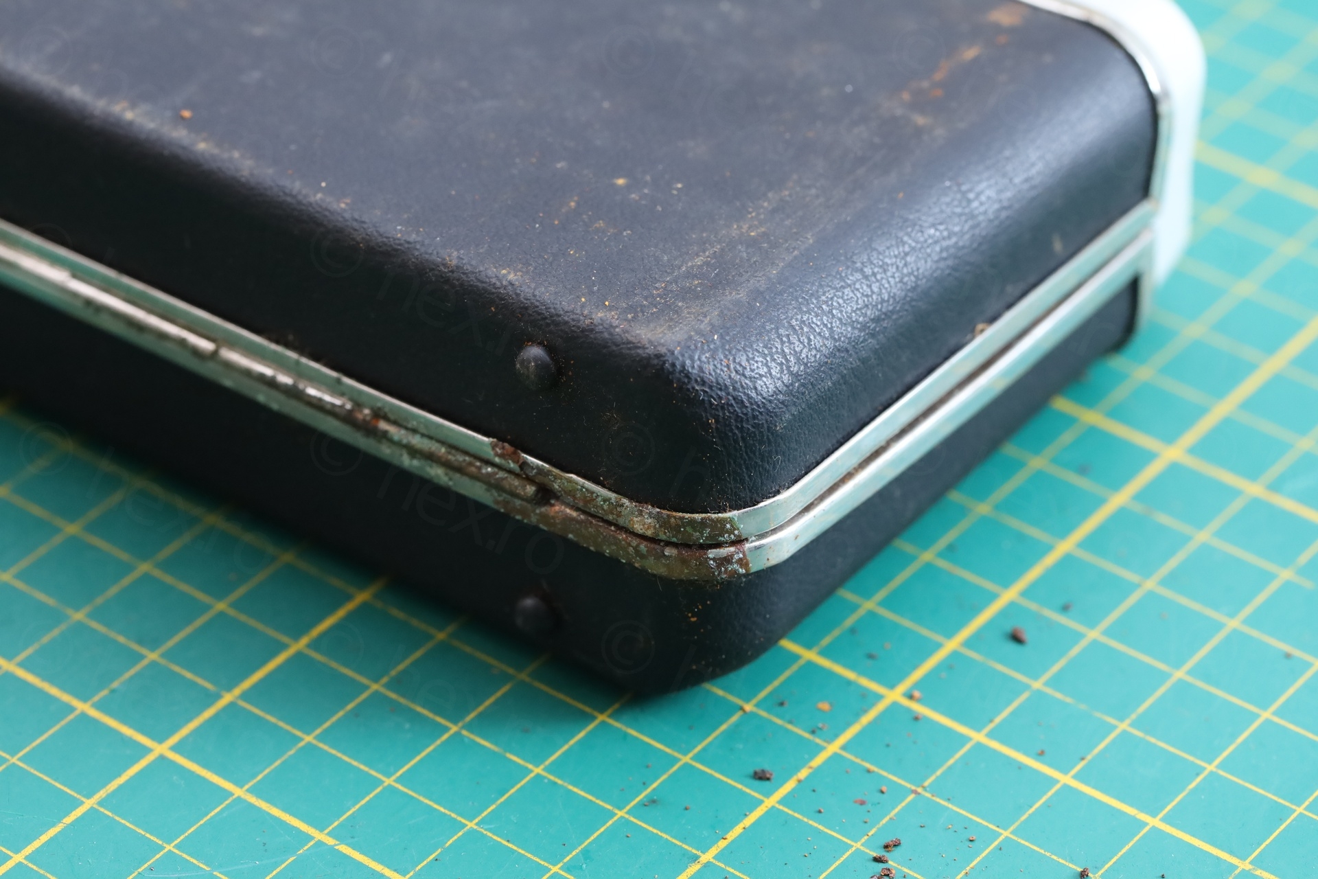
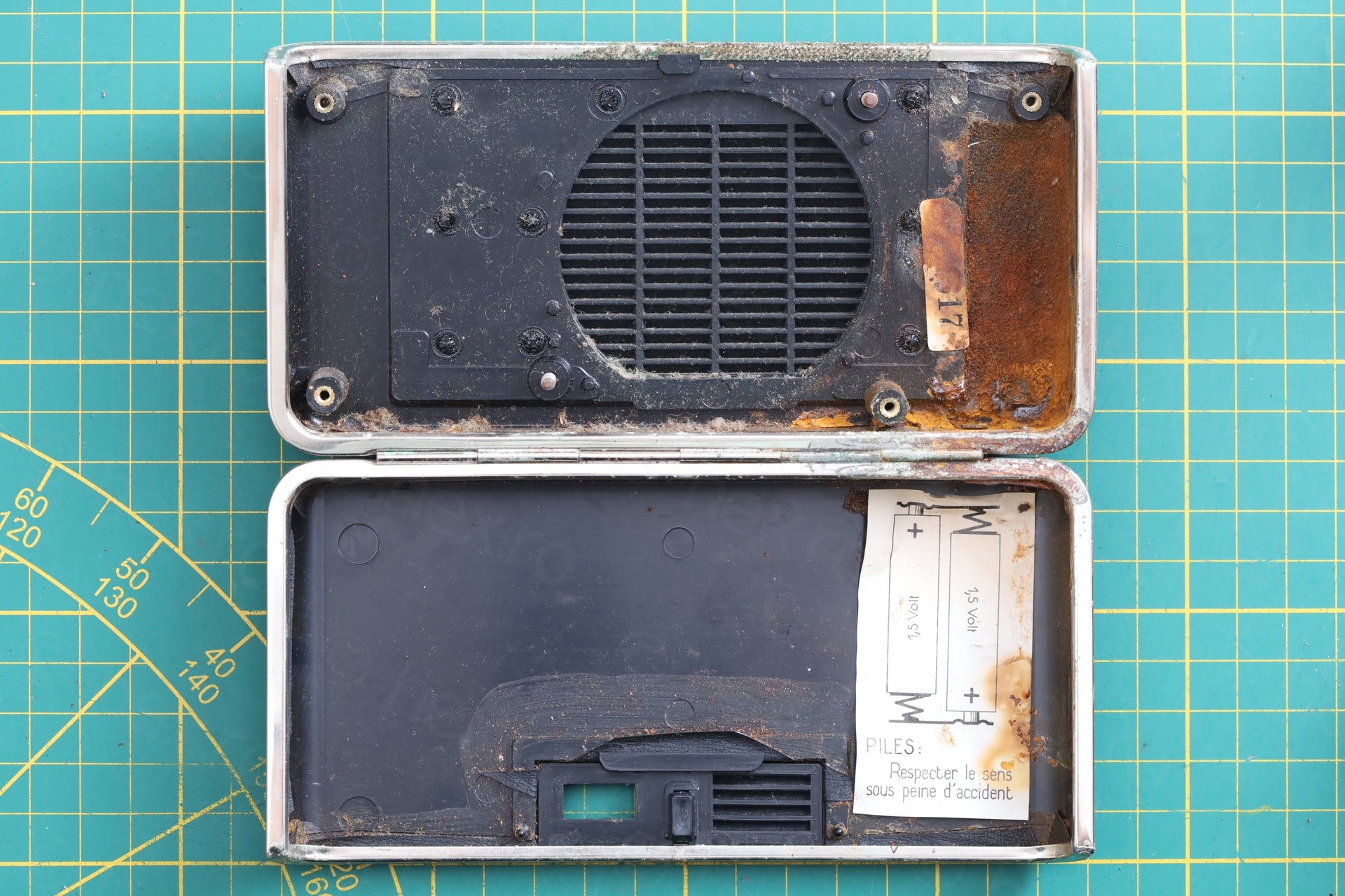
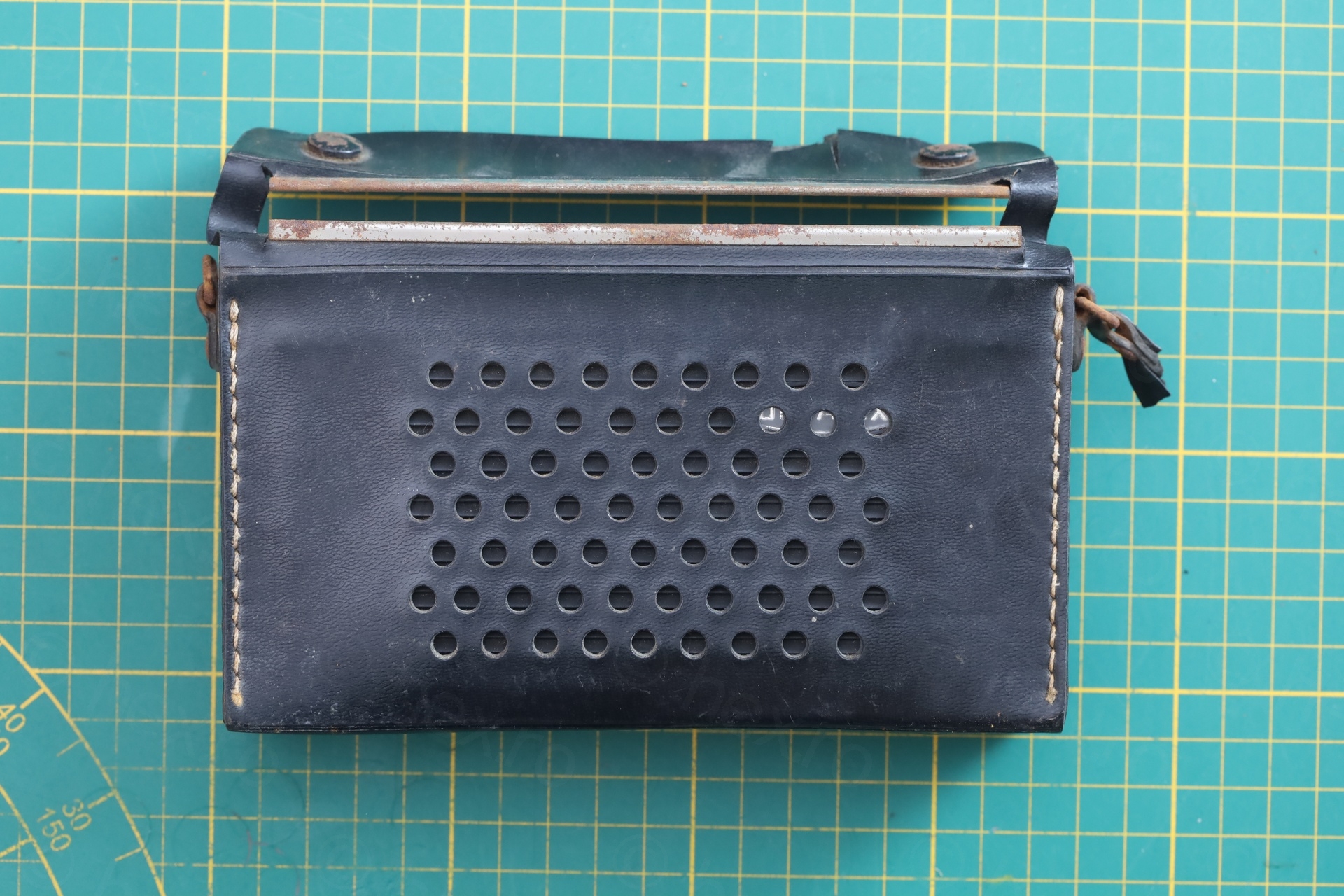
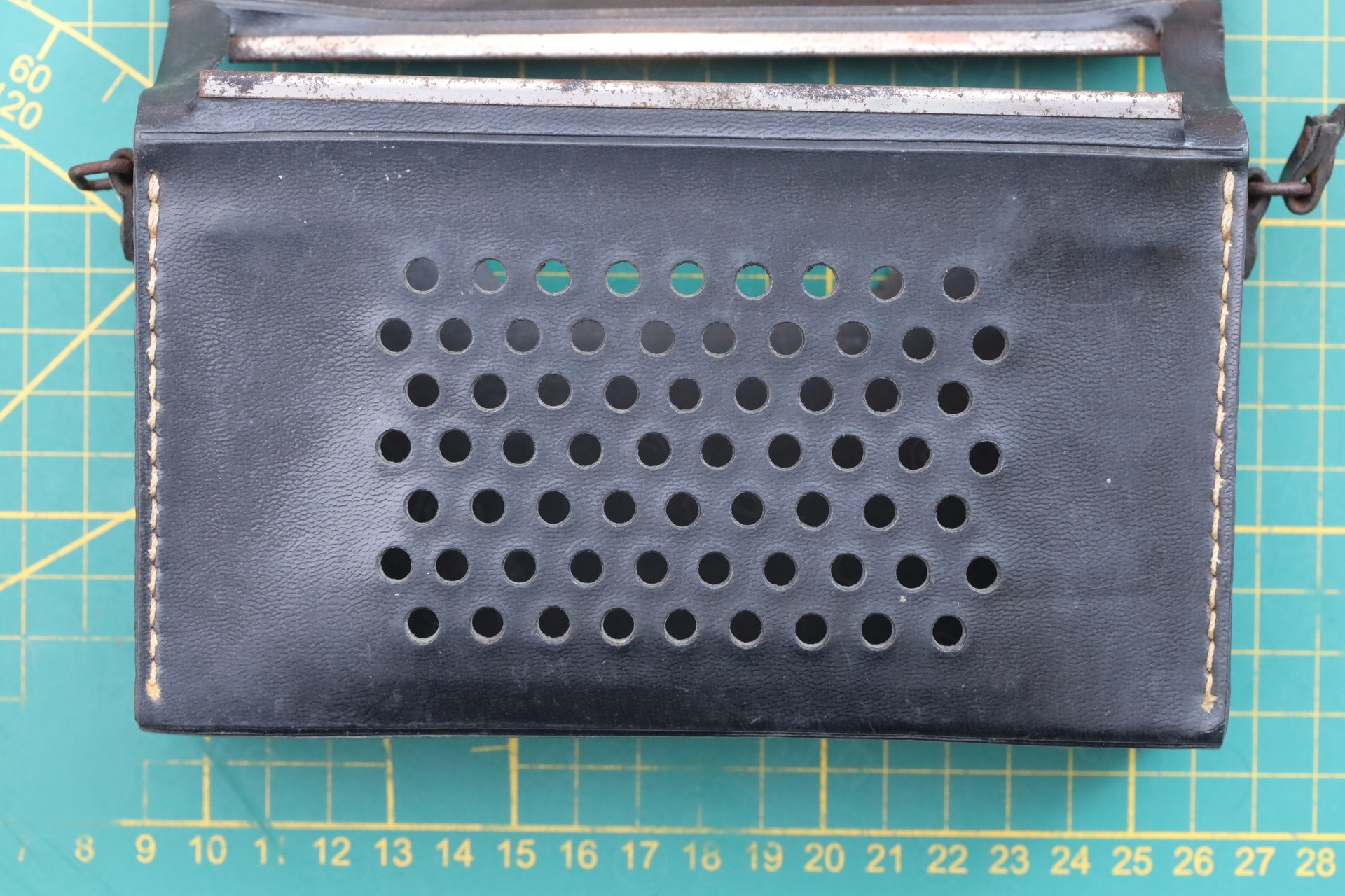
Photos of the outside of the radio as received:
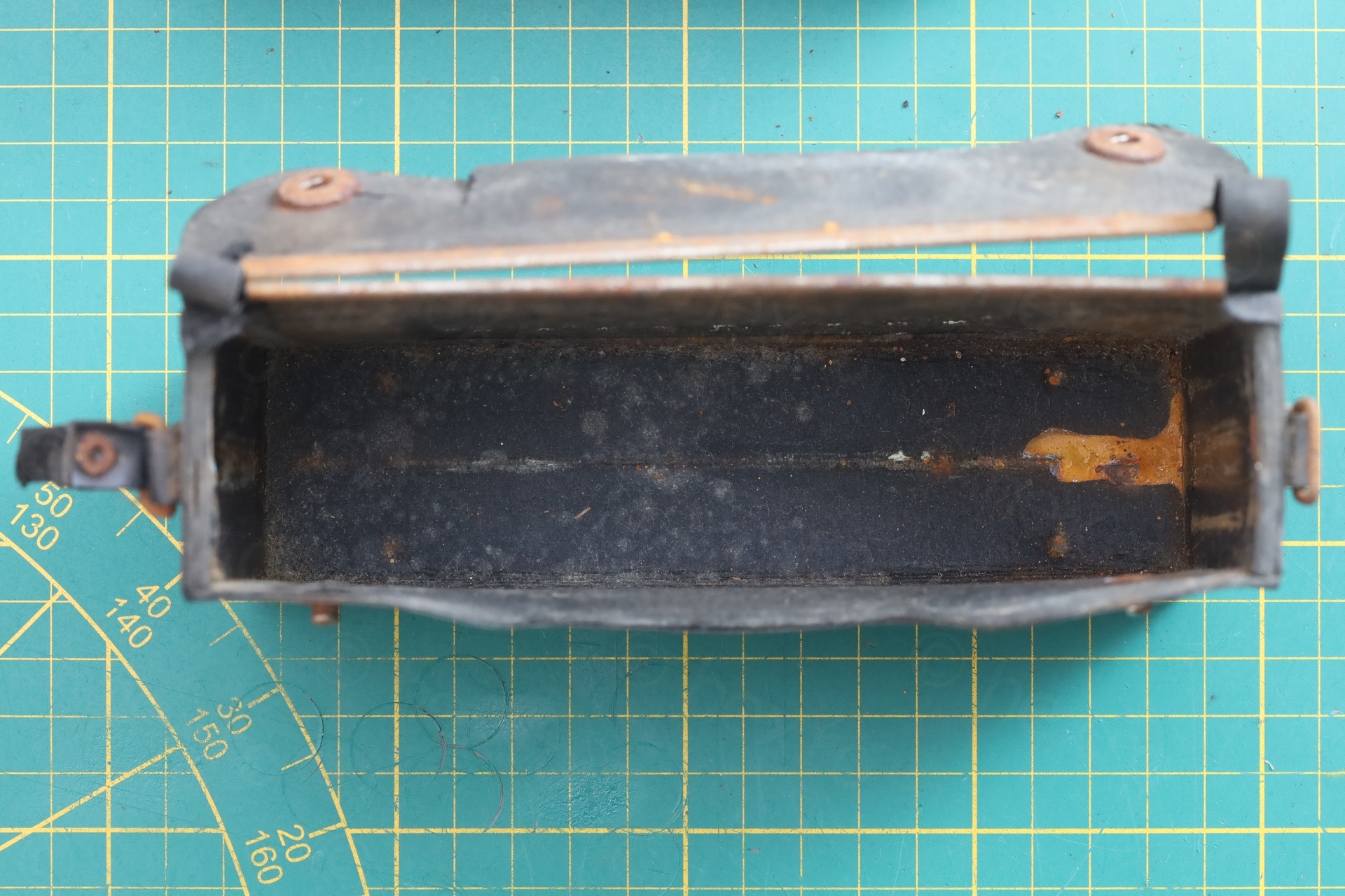

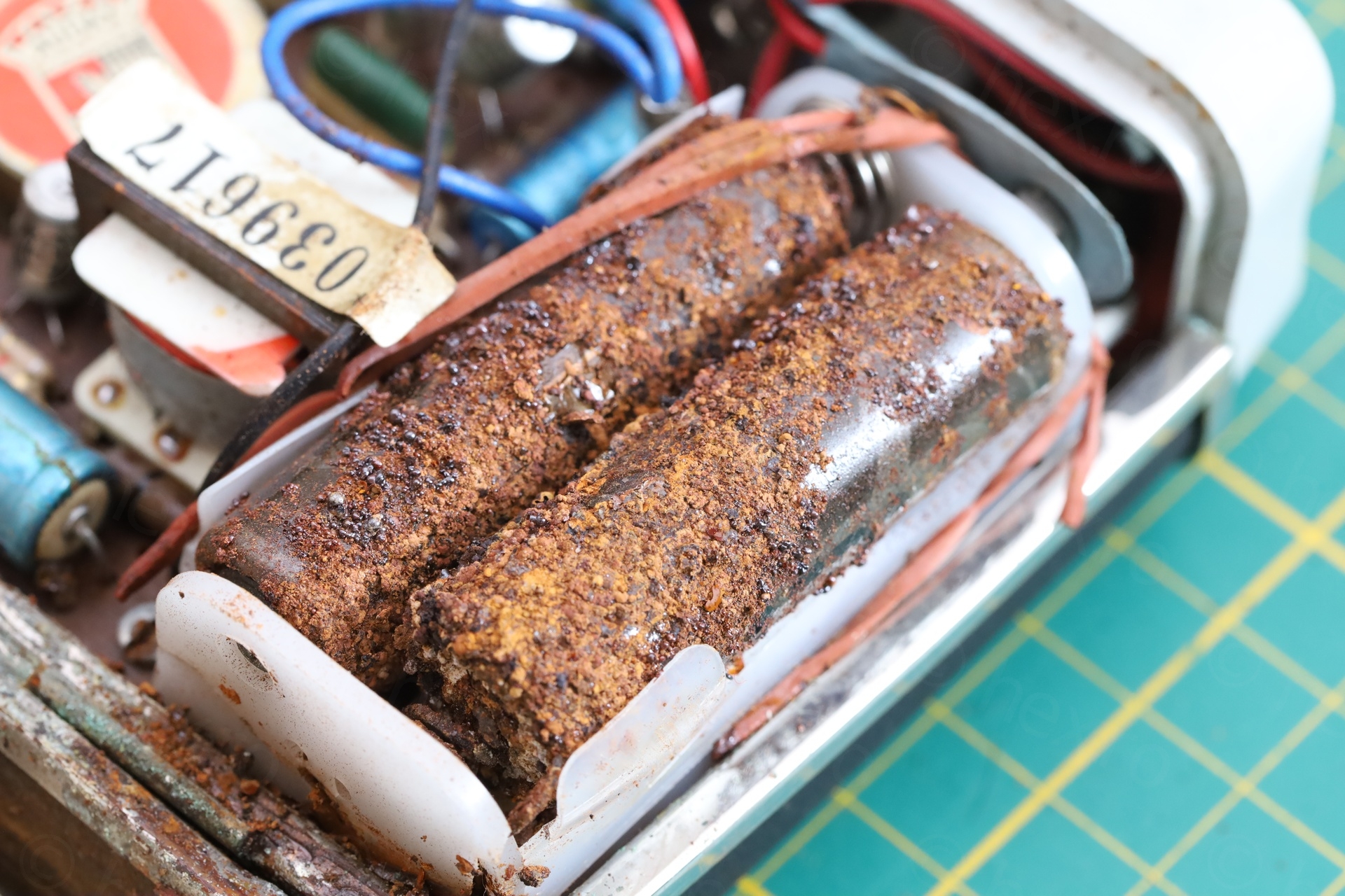
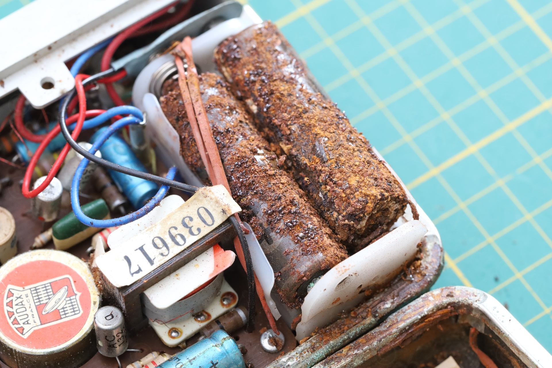
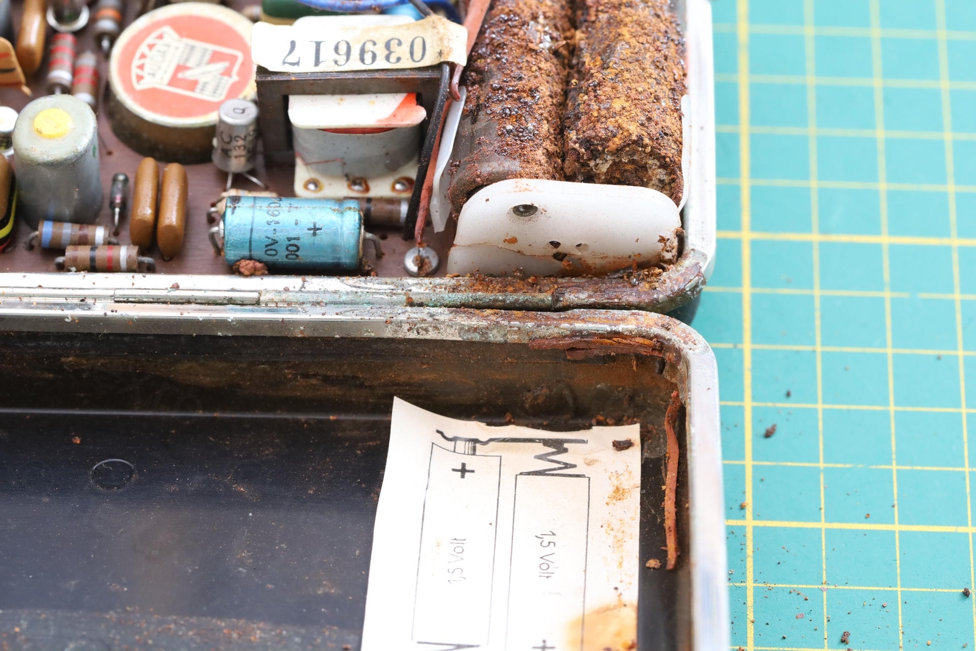
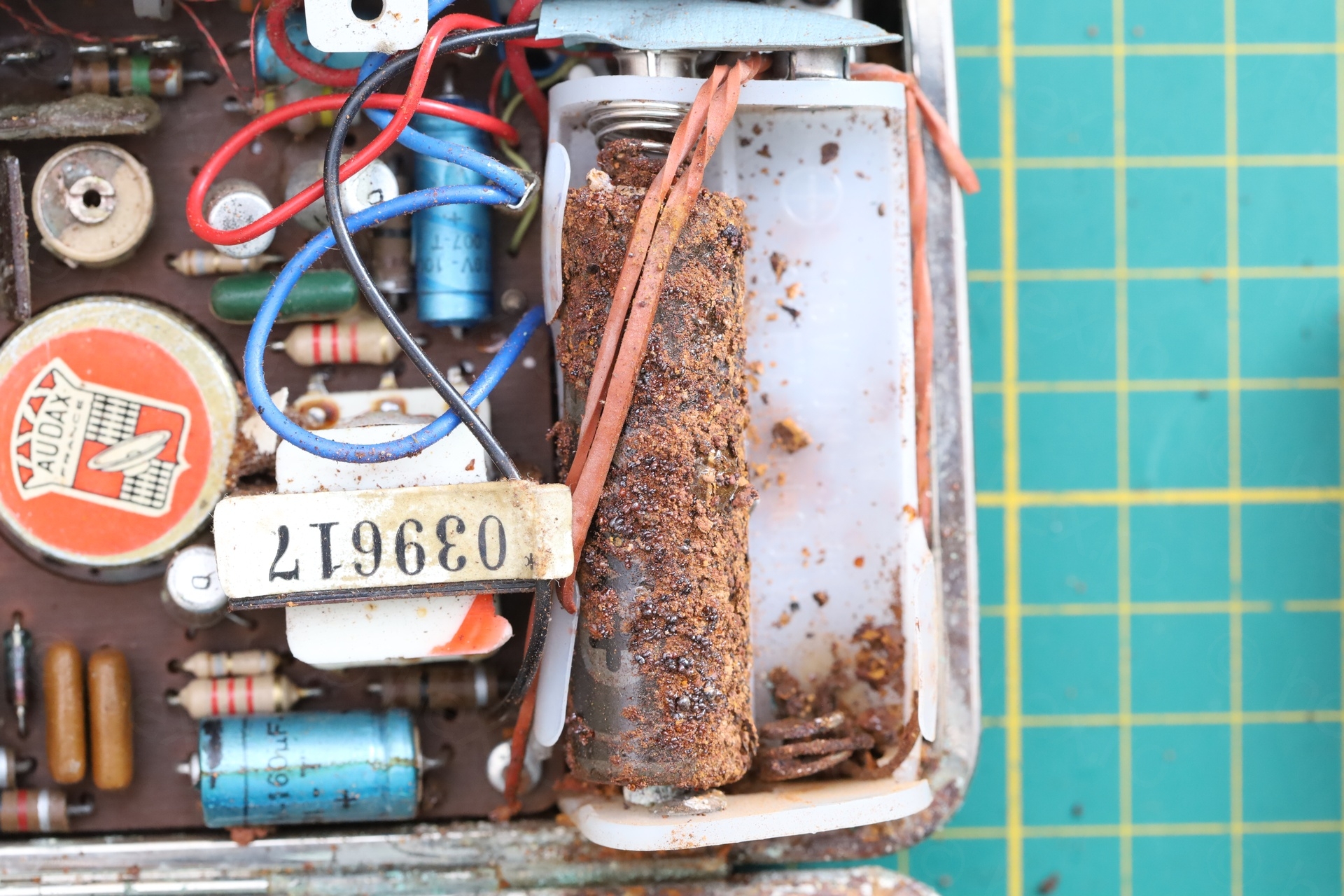
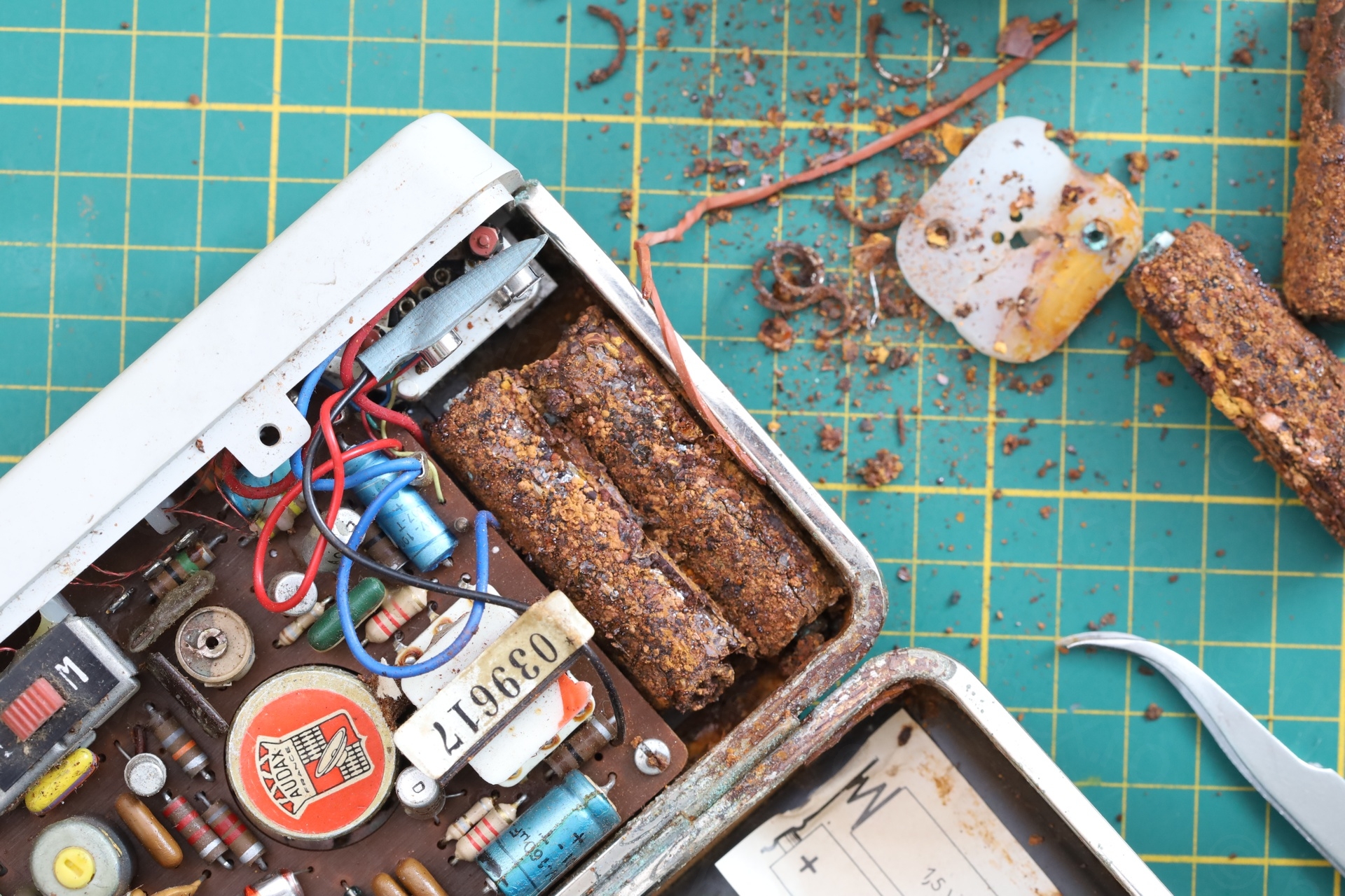
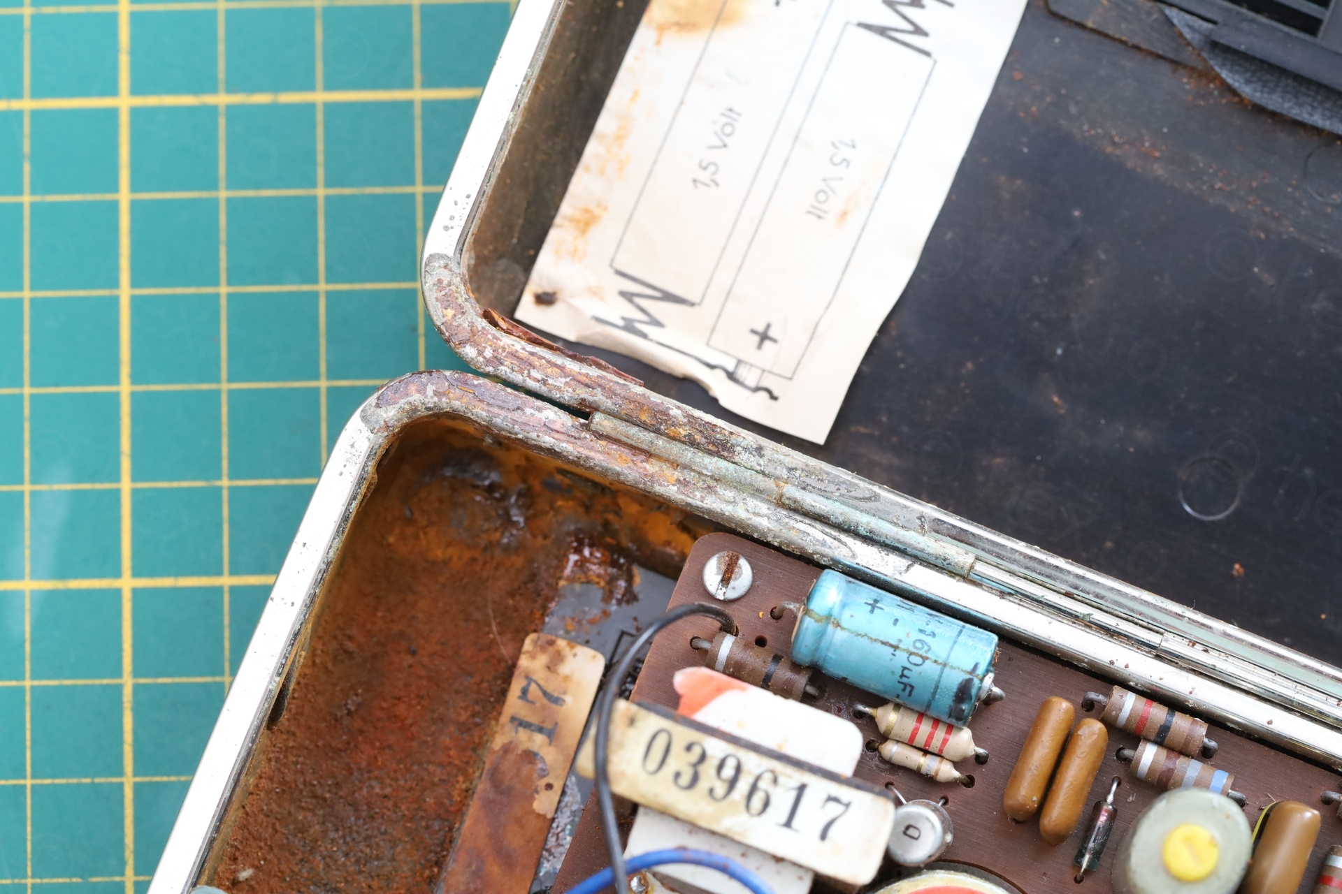
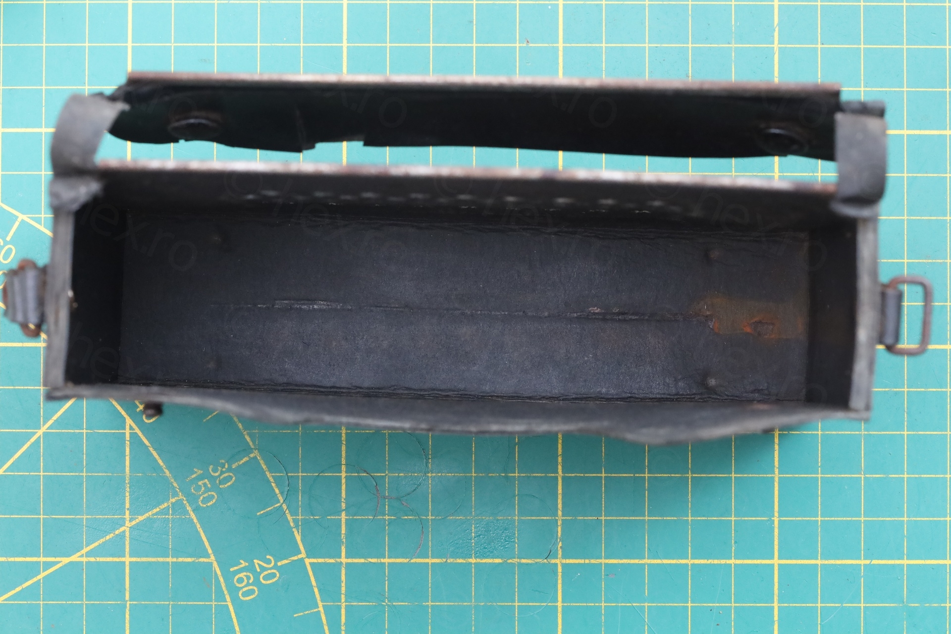
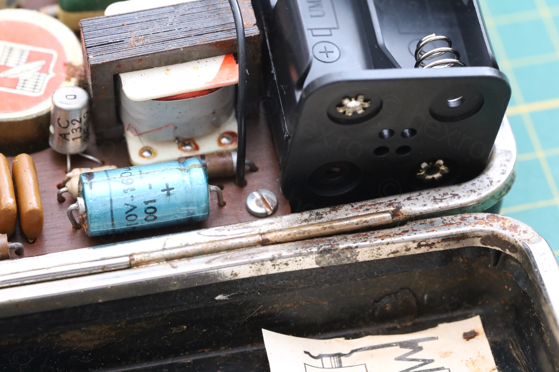
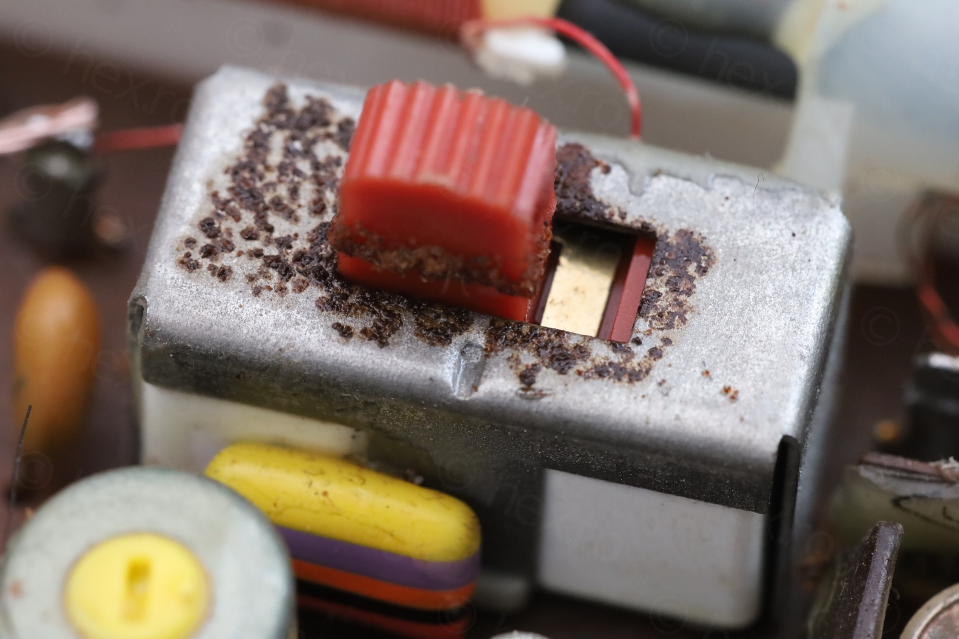
The batteries corrosion was impressive. I didn’t expect the holder to be intact and it wasn’t. The bottom right battery was very difficult to remove, it fused itself to the case of the radio:
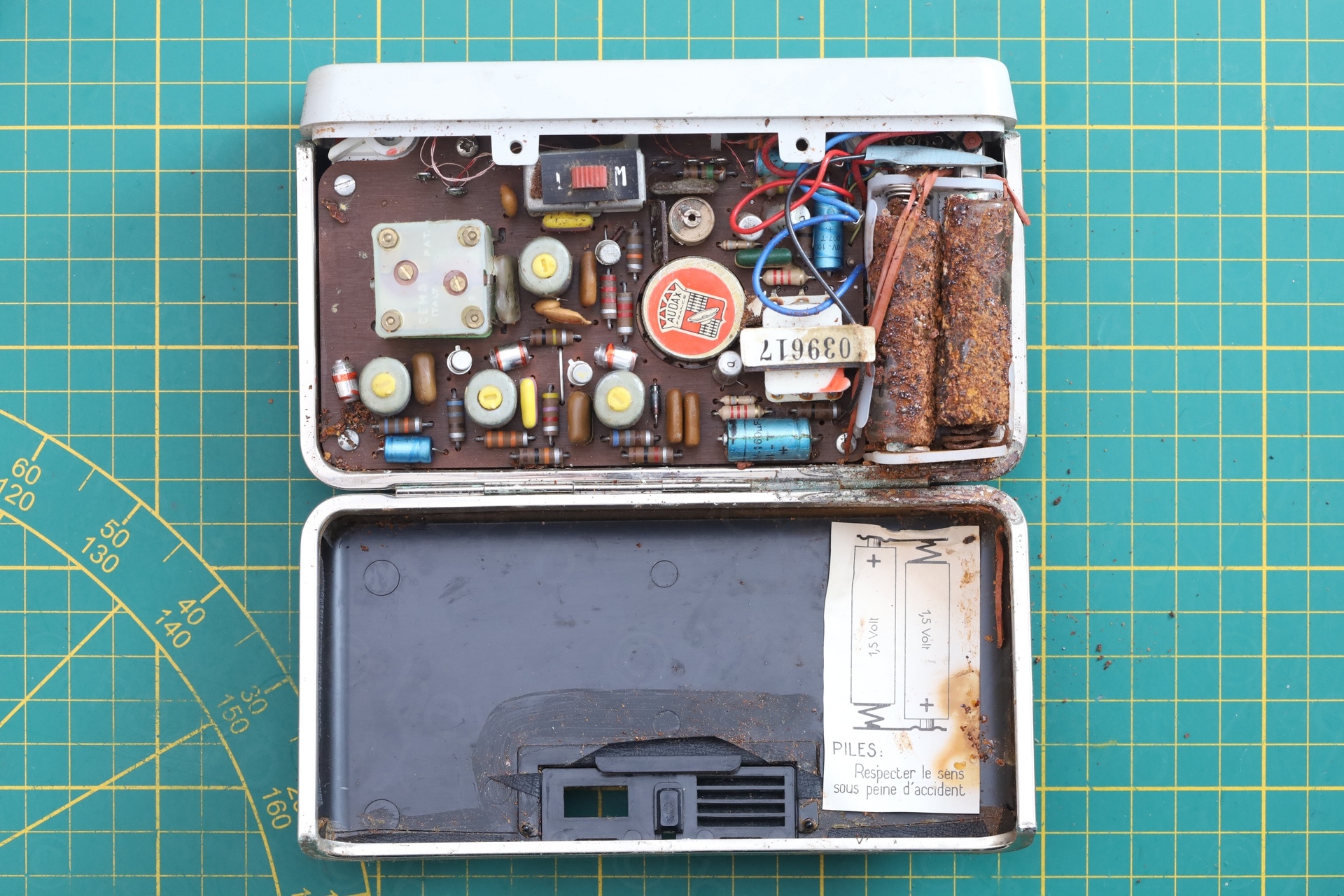
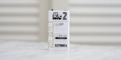
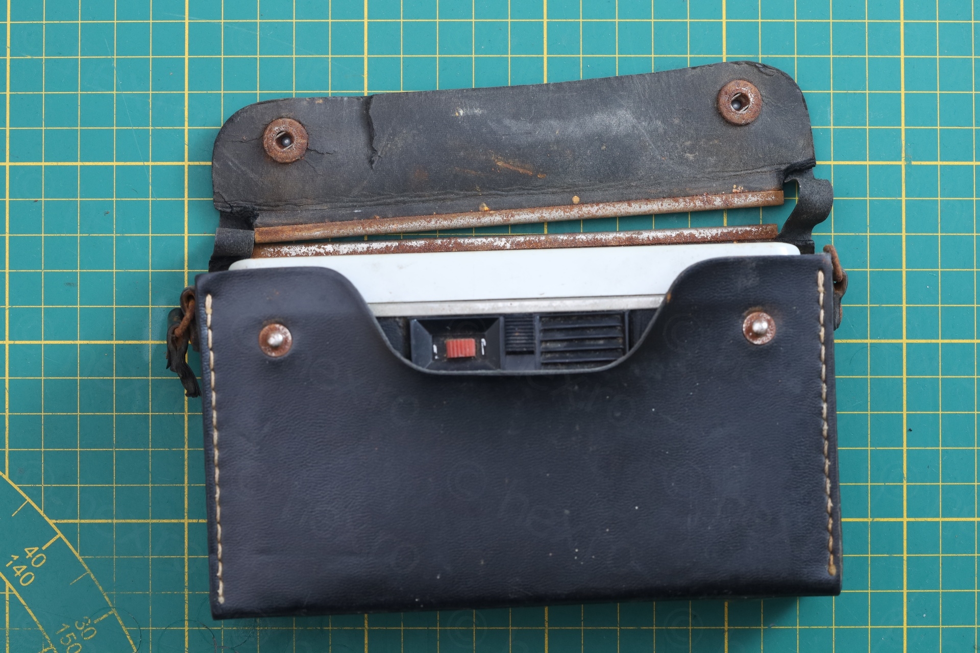
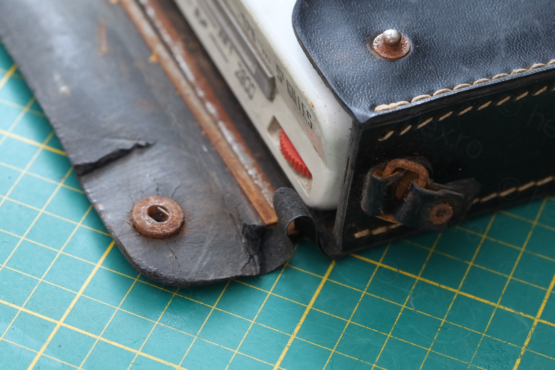
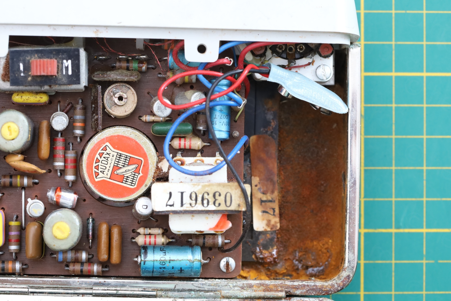
Few more shots with the inside of the radio – before opening it up:
Repairs
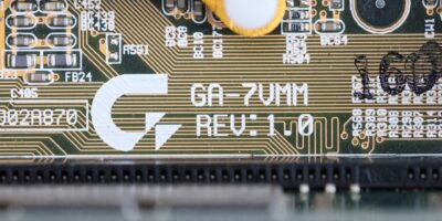
First order of business was to find the schematic and to hope that it contains the wiring diagram for the dial cord. Thanks to the people contributing to https://www.doctsf.com/optalix-saint-gilles/f2196 I found it and the wiring diagram is included!
A quick test revealed that the radio receives fine, thus the repairs were re-stringing the dial cord, remove all the rust and re-fit a new battery holder.
Electrolytic capacitors behaved fine, none having horrible ESR. Just to make sure, paralleling with known good capacitor didn’t change anything in the performance of the radio.
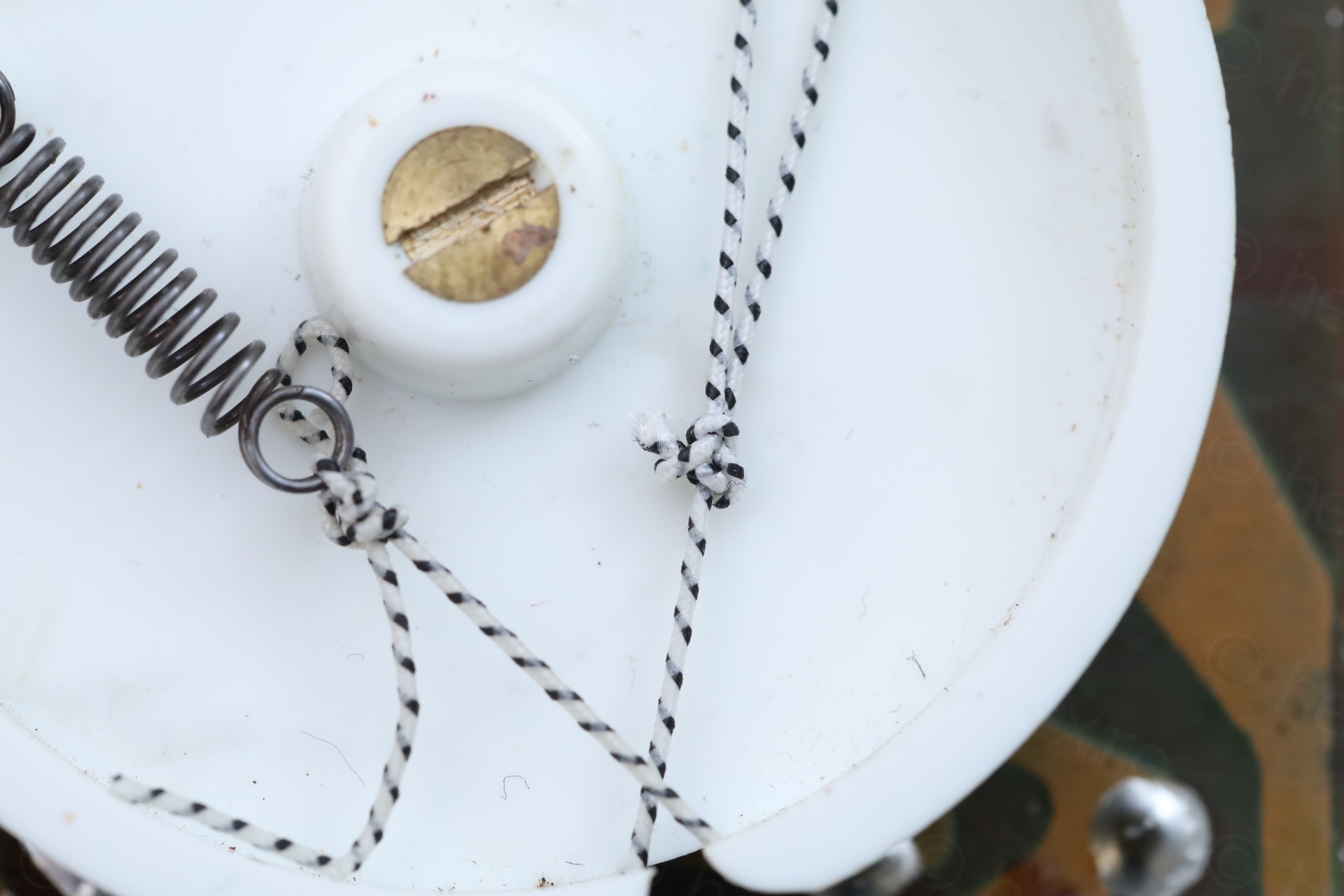
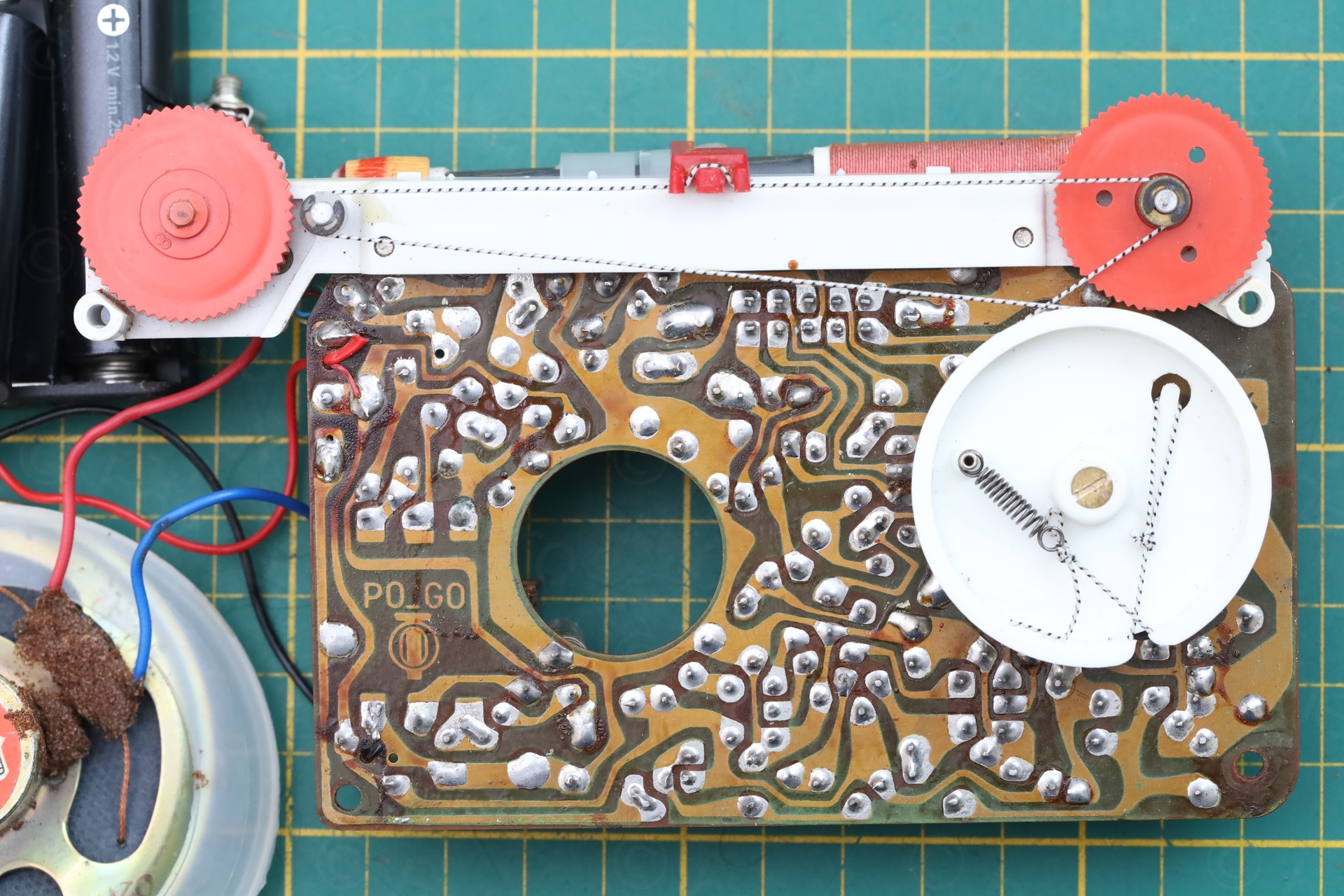
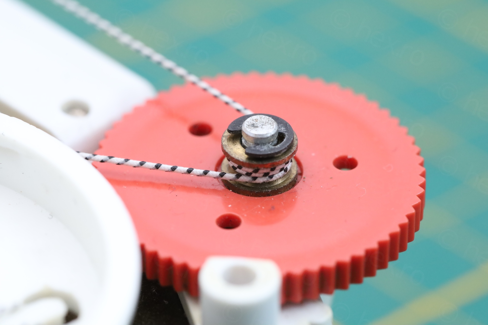
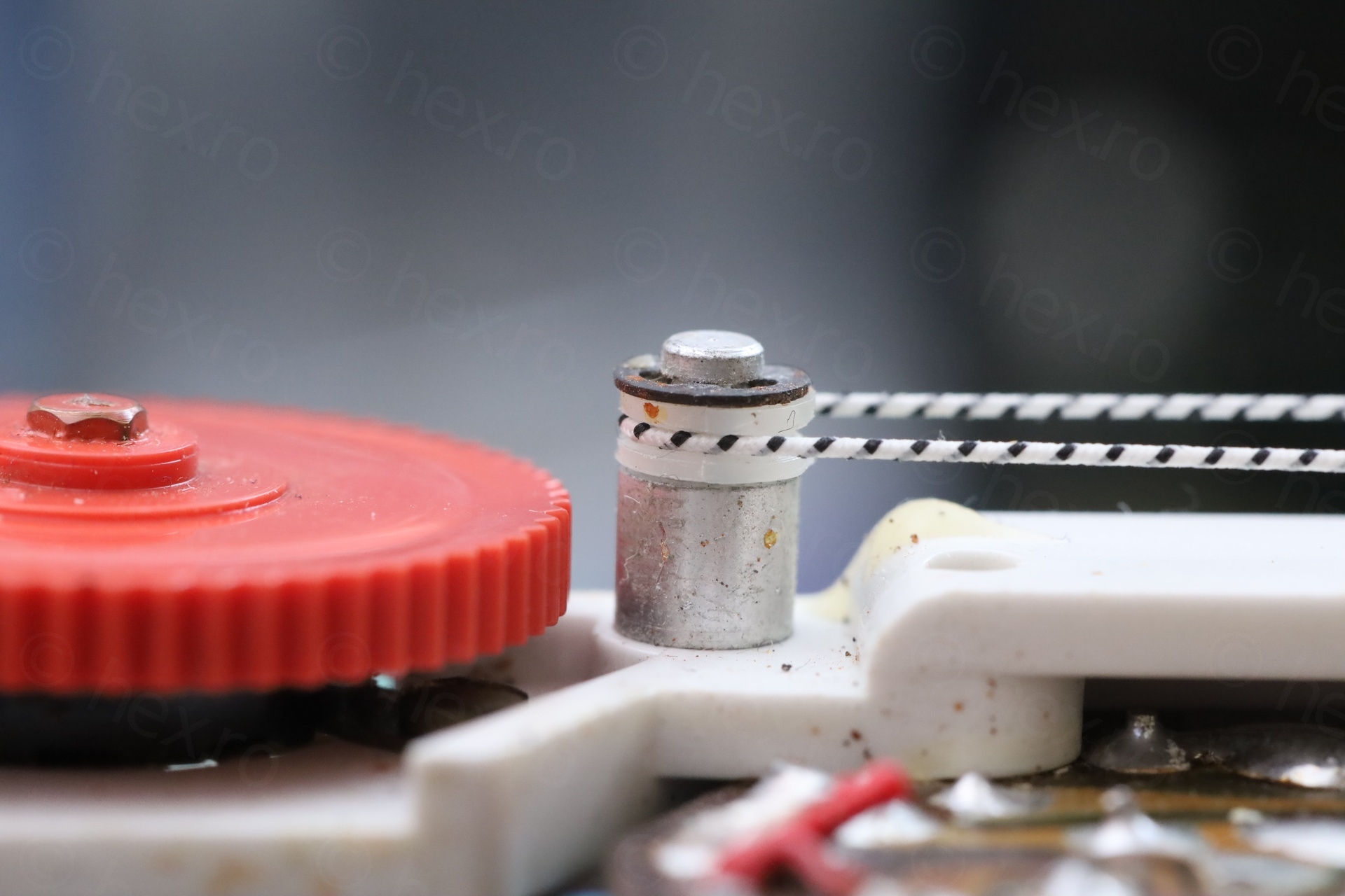
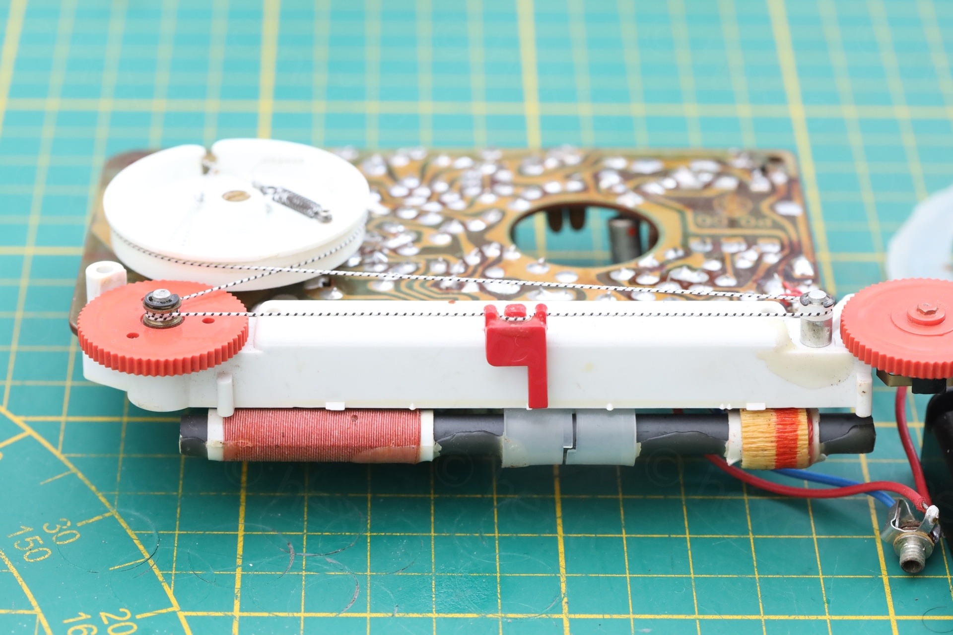
Re-stringing new dial cord
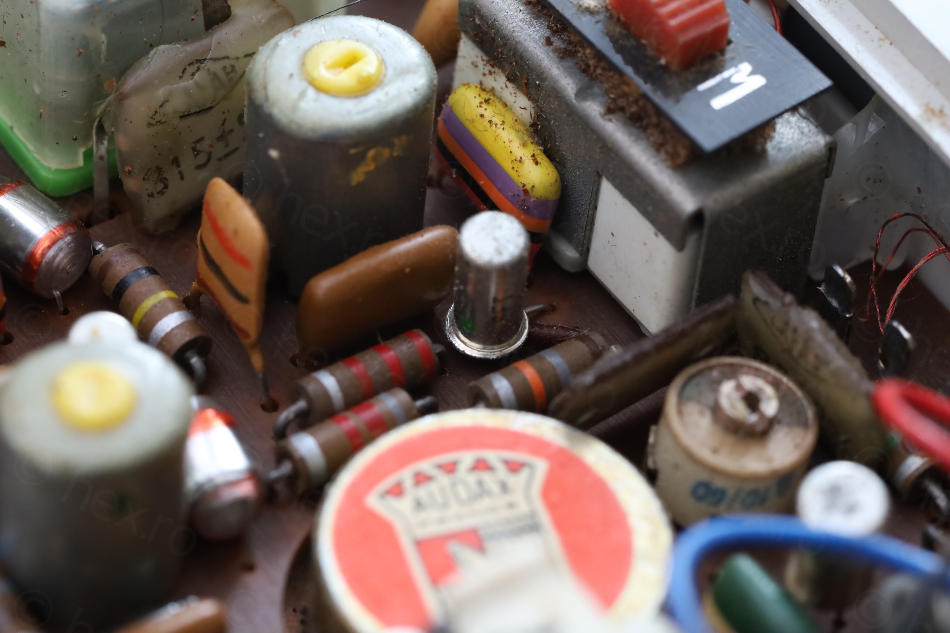
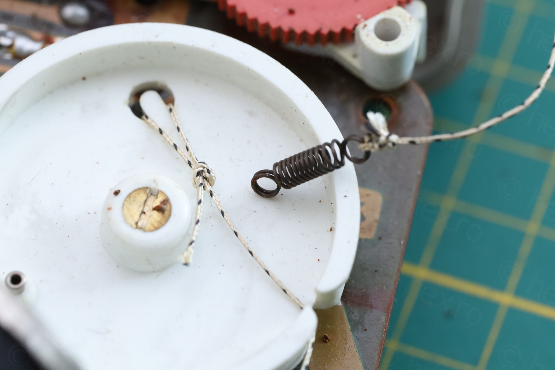
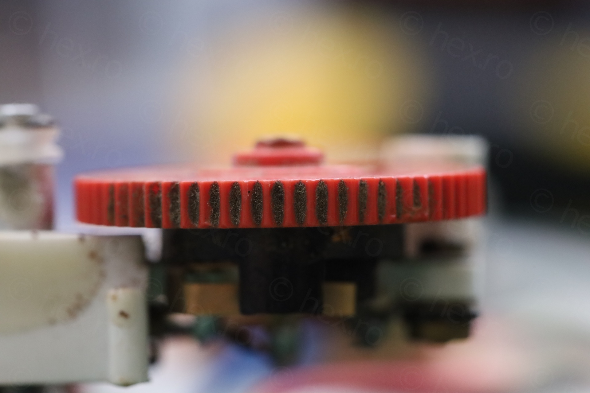
I photographed everything I could – in the hope it would be of help:
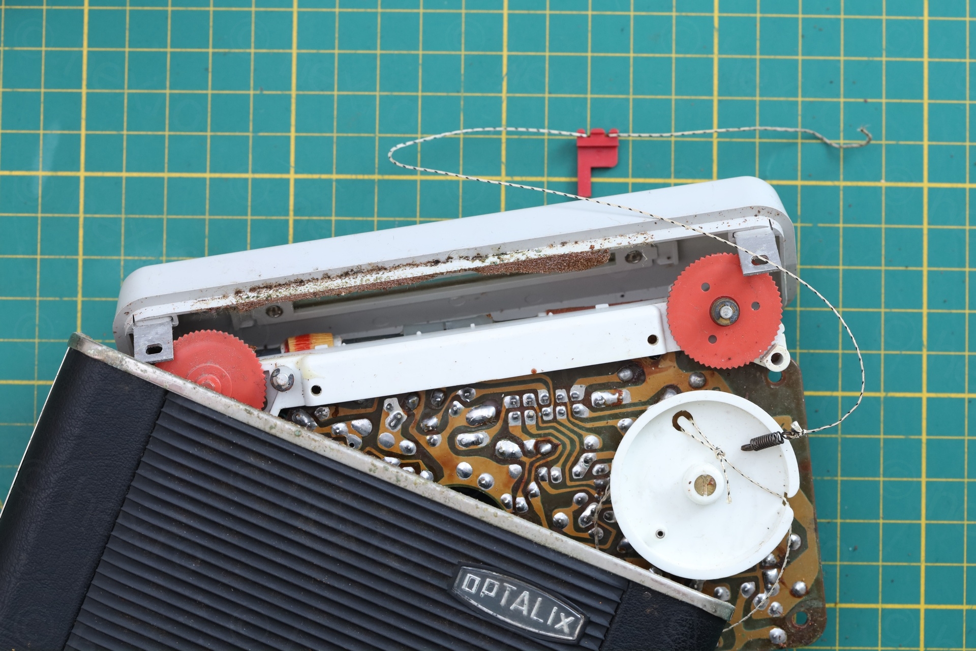
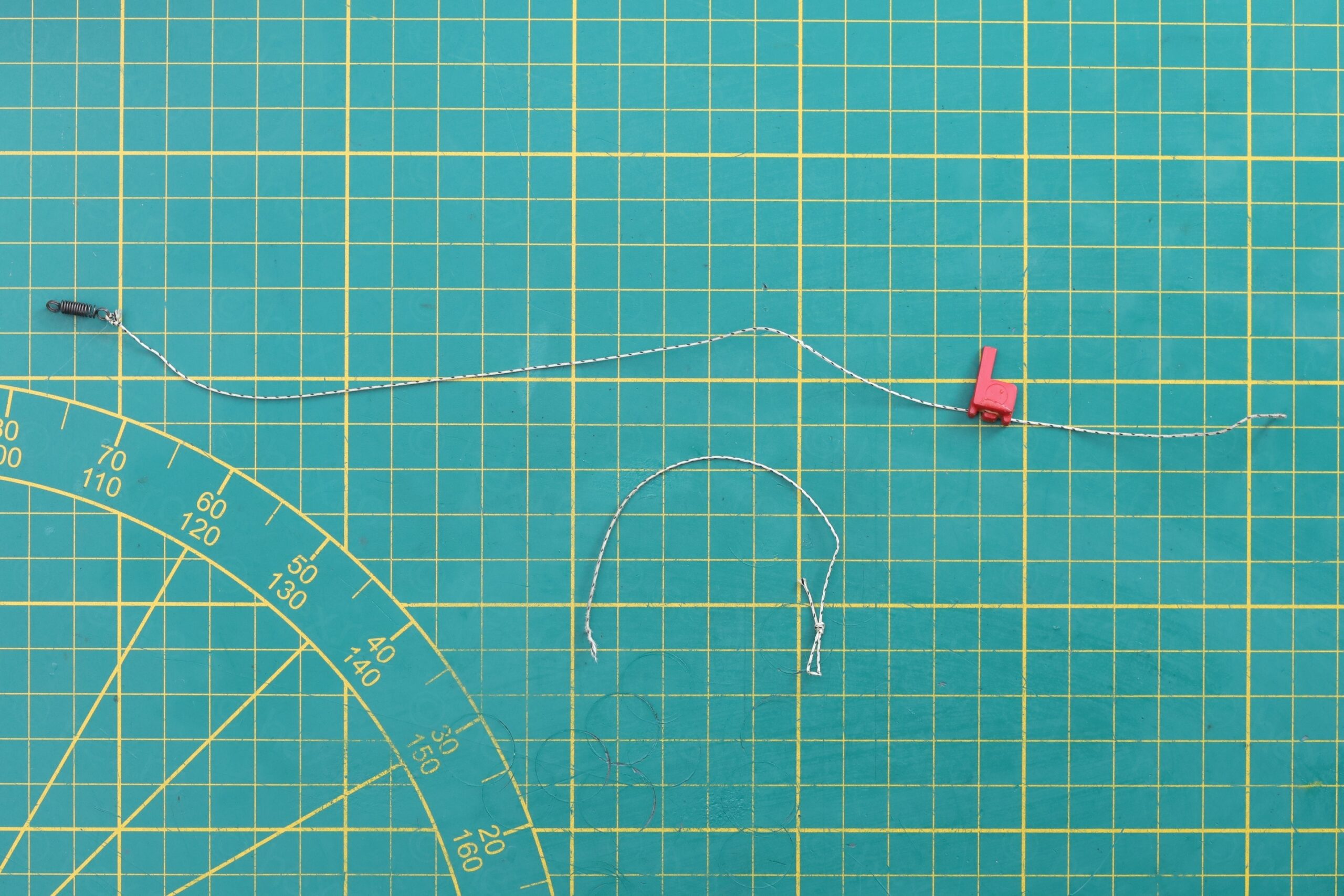
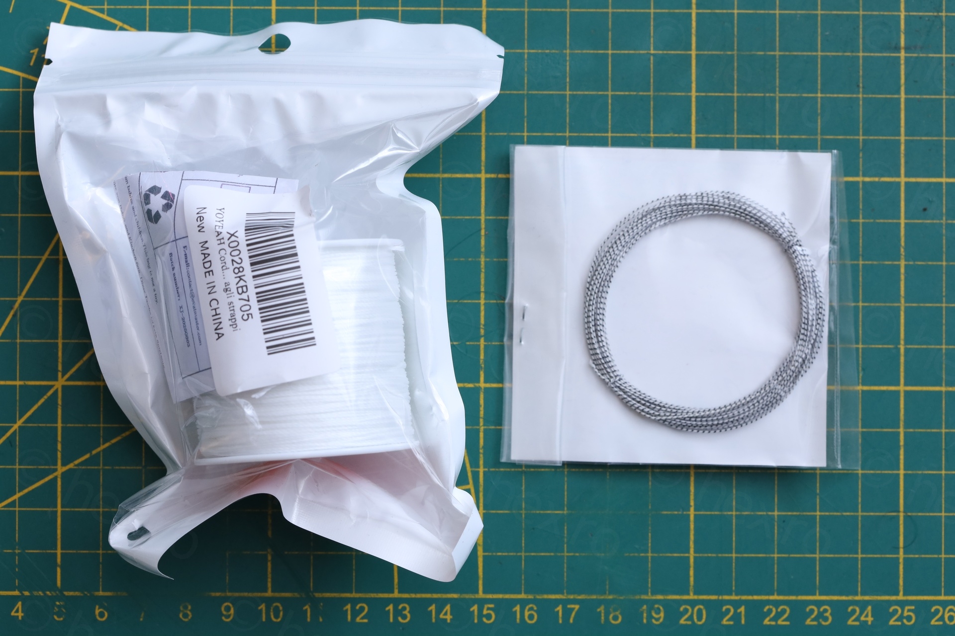
The dial cord seems to be around 0.5mm thickness.
I spent too much time trying to sort this out:
- I ordered both dial cord (expensive), as well as waxed nylon cord replacement.
- Hoped that I can use the waxed nylon cord and save the dial cord, it turned out, it was easier to use the dial cord.
- And what knots should I tie ?!
Since I needed to practice the knots, I decided to go with the plentiful white cord. Ended up using the “Perfect Loop” knot for one end and simple Half Hitch knot followed by a Slip Knot. The world of knots is so complicated, I have really watched too many videos on this, at least to use the right terminology..
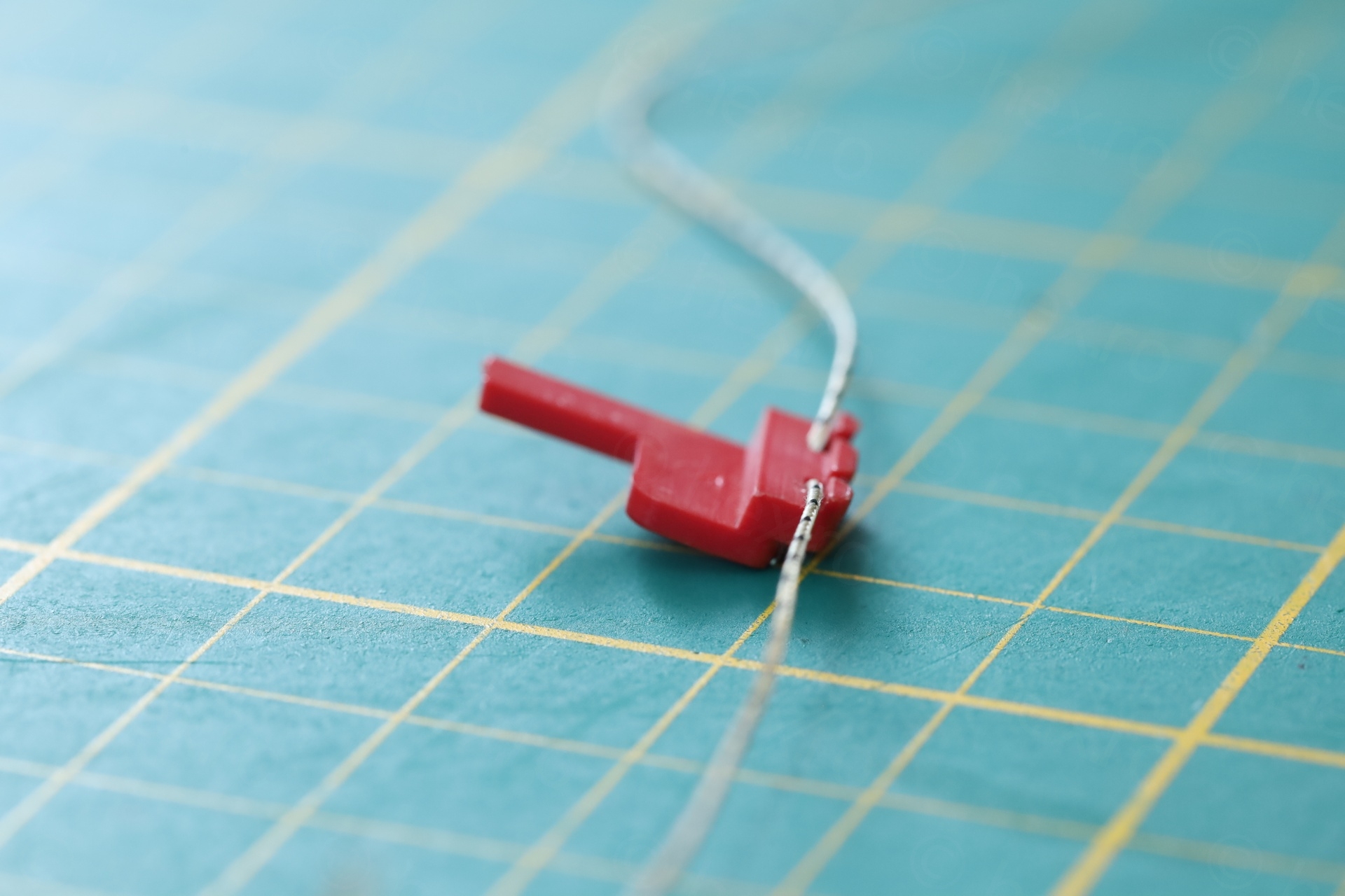
Here is the first successful attempt – using the waxed nylon cord – but notice please, how much it twists / rotates where the dial pointer would be attached (dial pointer improvised with a bit of sticky label from a Dymo printer):
Having gained enough confidence in tying the knots – and since I wanted to preserve the original look of the radio (stripped cord, not white chord), I went ahead and switched to the radio dial cord.
Night and day difference. Much easier to tie the knots – and only rotates just a little bit.
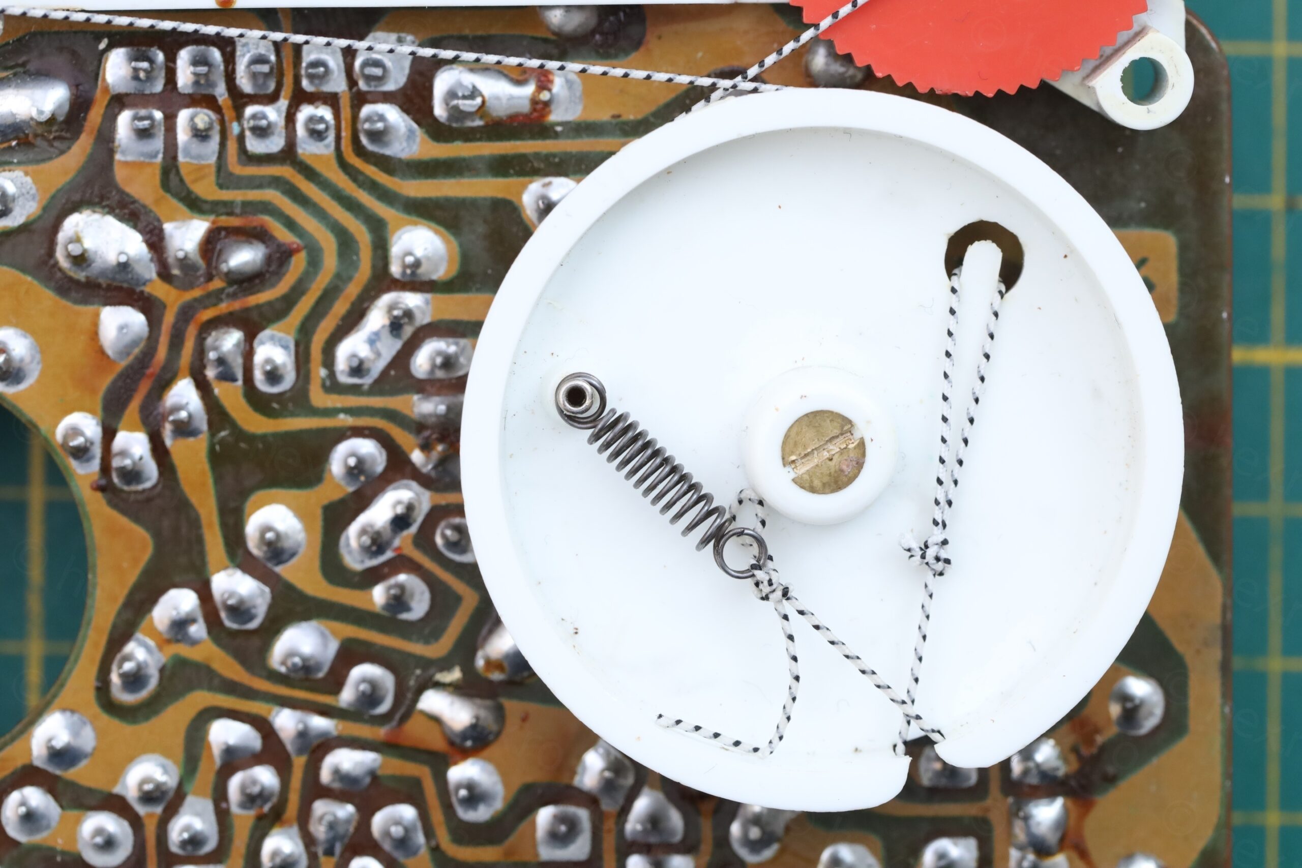
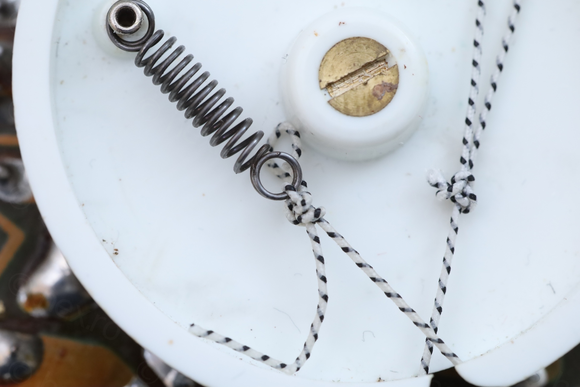
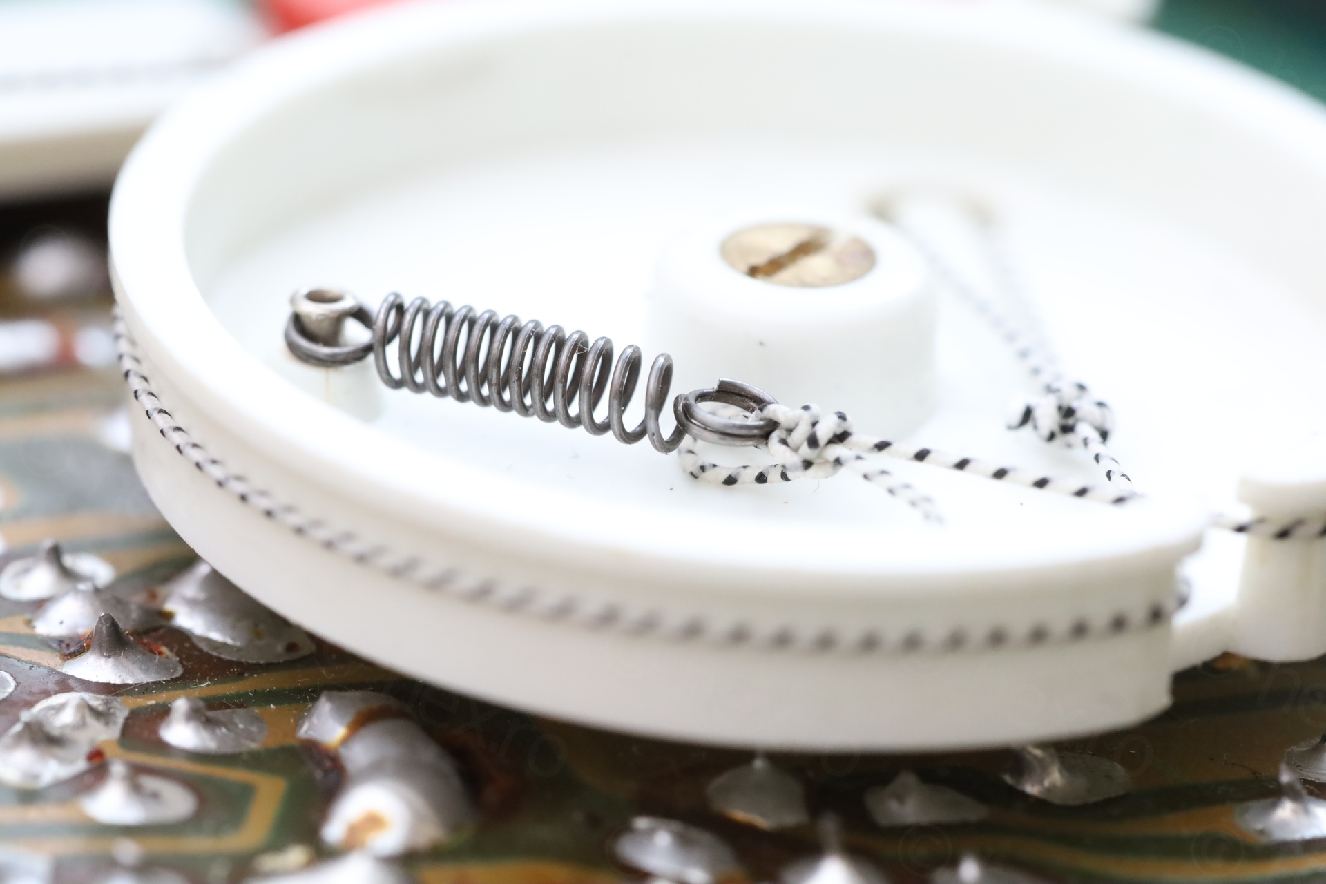
The special purpose dial cord has a lot of friction, just a simple Half Hitch knot keeps it attached to the spring under tension. With most of the knots, it is very difficult (for me) to control their exact position, once you pull on the cord to tighten them. Thus, having a simple Half Hitch still staying attached to the spring, under cord tension, made it a lot easier to control the length / tension. I only needed 5 or 6 trials 0:-)
About attaching the dial indicator, I didn’t pay too much attention to its alignment with the scale. I had 2-3 tries to get it “centered” – in the sense that when it is at the left most position, it sits 5mm away from the left side of the dial window. Same on the right, 5mm away from the right hand side of the dial window.
Removing the grime
Waiting for the cords to arrive, I focused my attention to removal of rust. It reached many places:
- The case just behind batteries – I cleaned it with lots of alcohol and scrubbing.
- The metal parts on the radio hard-shell case, I used a grinding pen + Fertran
- For the plastic parts, just normal de-greaser ..
Photos with before / after are below.
The insides of the radio:
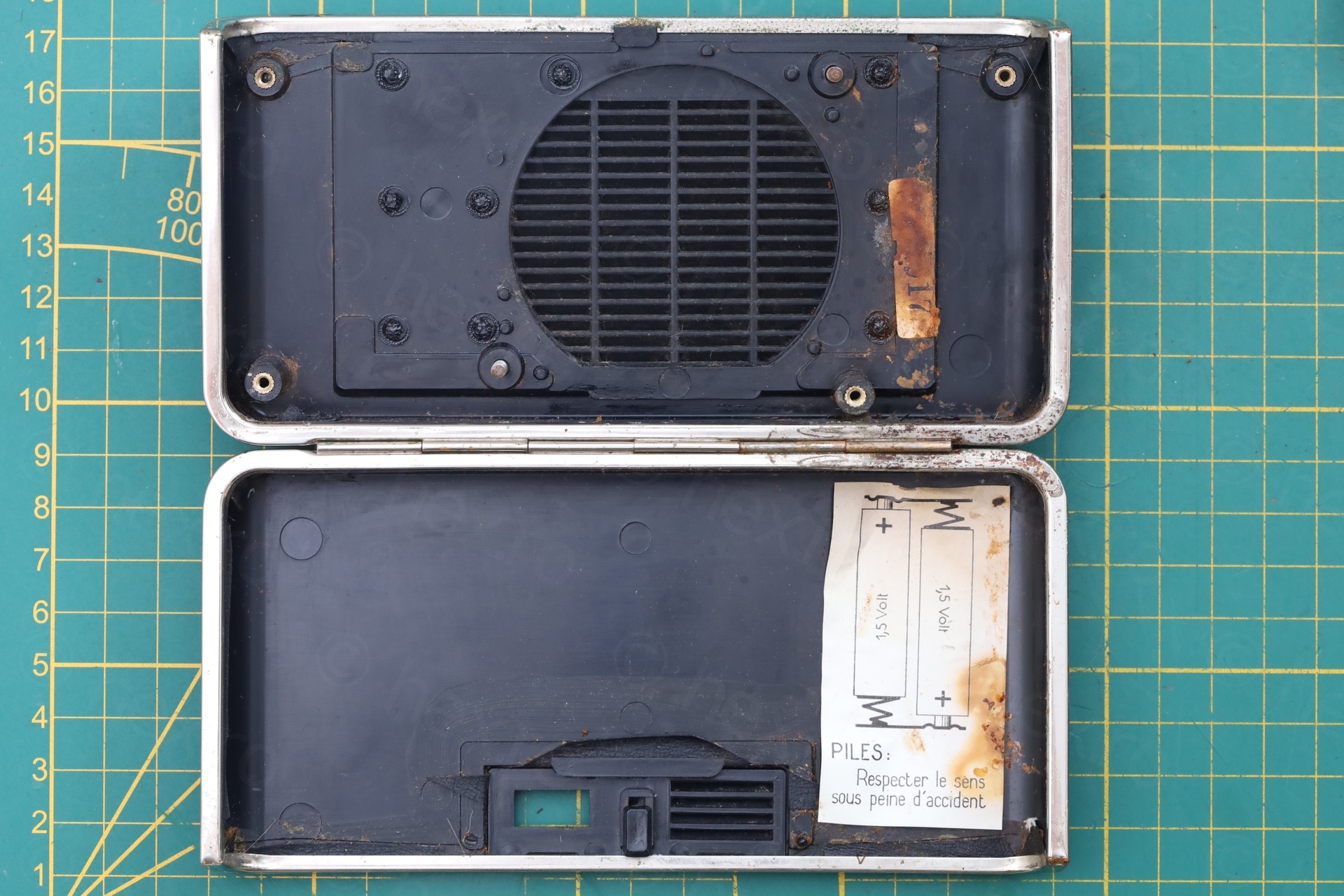
With the case:

The knobs:
The top of the radio:
Replacement Battery Holder
Radio was put together now, the last remaining this was re-fitting a battery holder.
I did order a set of battery holders with snap terminals, but surprise surprise, it would not fit!
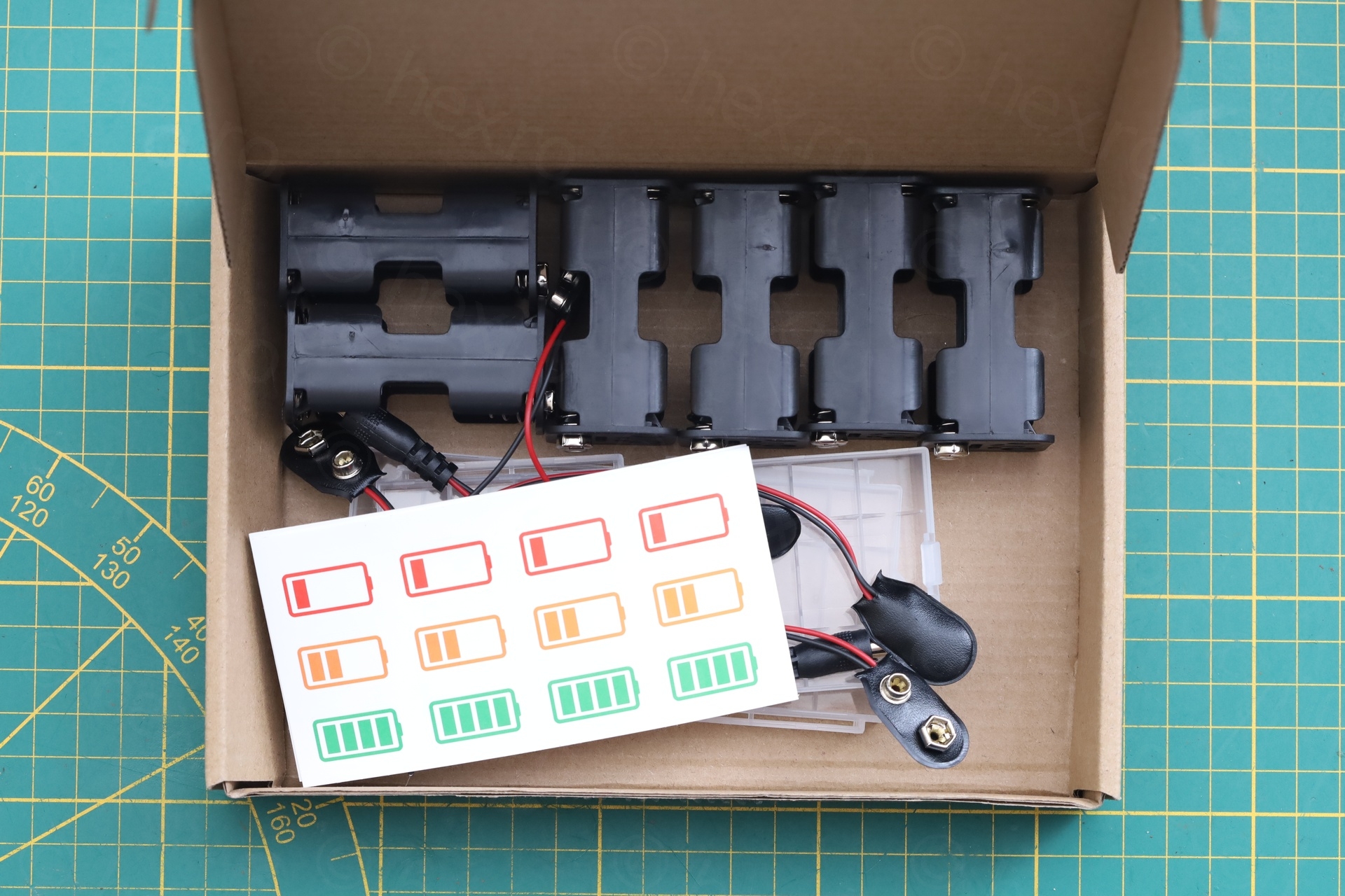
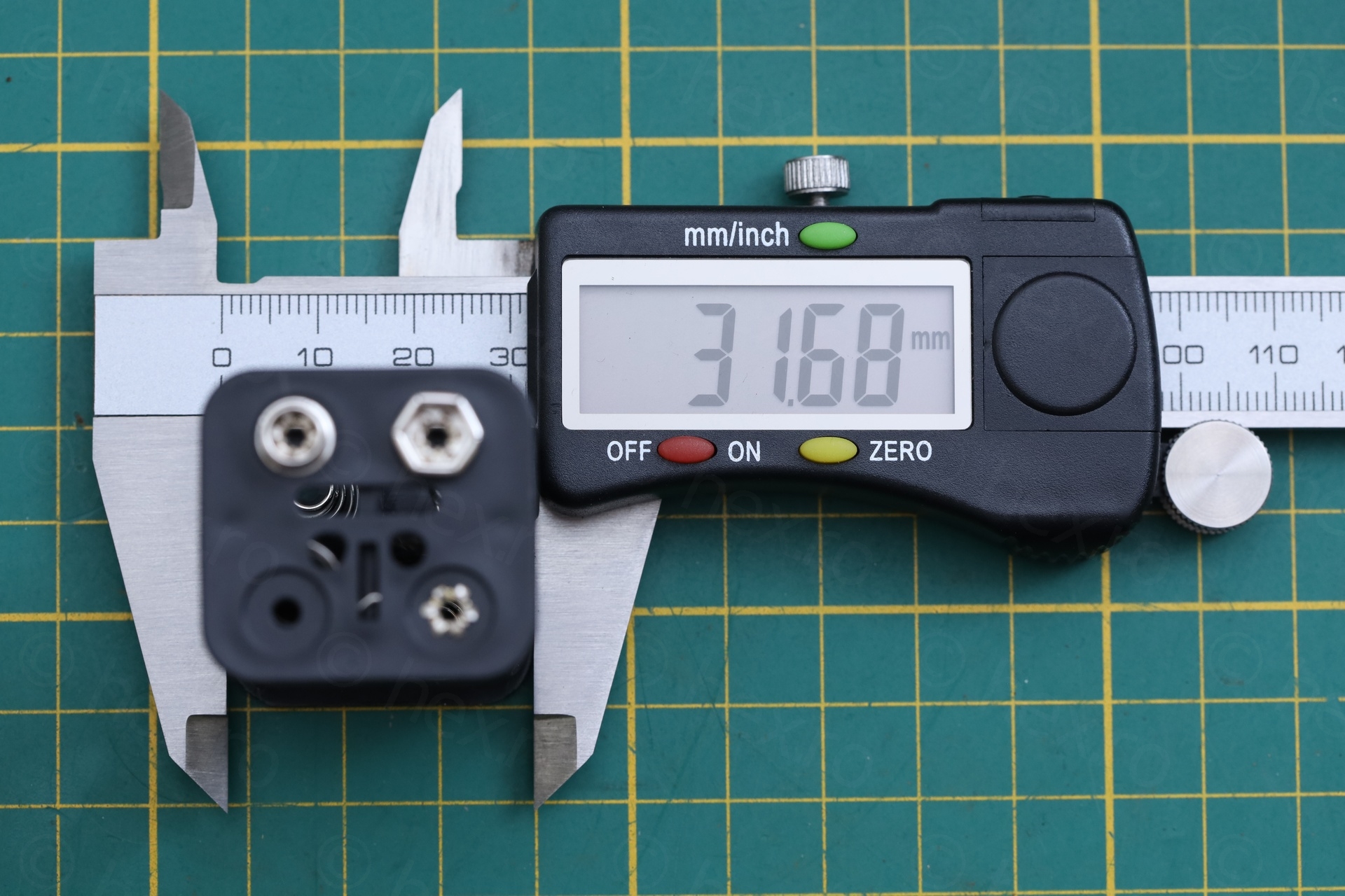
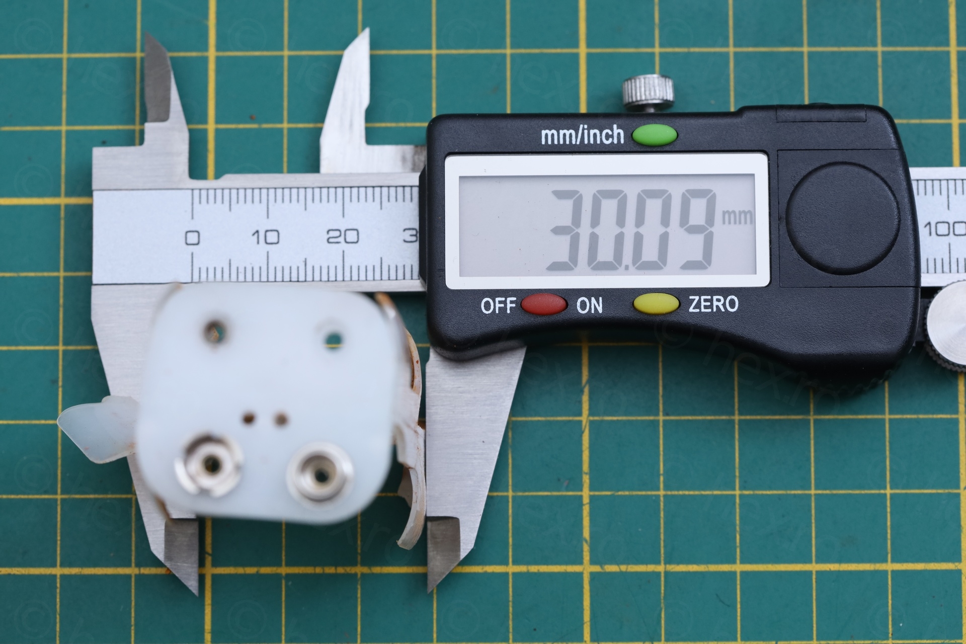
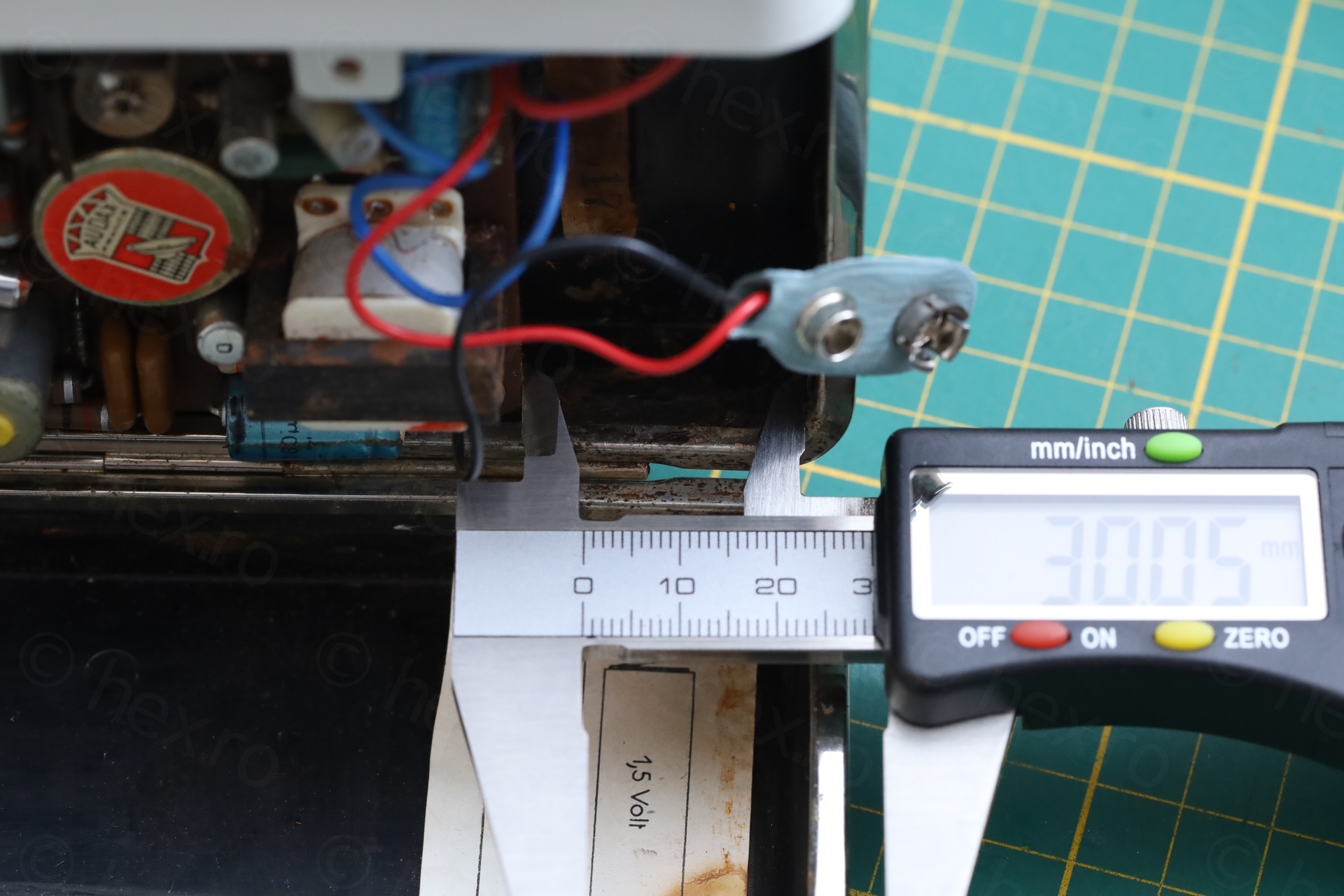
The radio seems to have enough space to fit a 30mm wide battery holder – but most of modern replacements are 32mm +/- 0.5mm, with the “smallest” I found being 30.5mm. It may be that the 30.5mm could fit – but until I’d get one, what to do ?
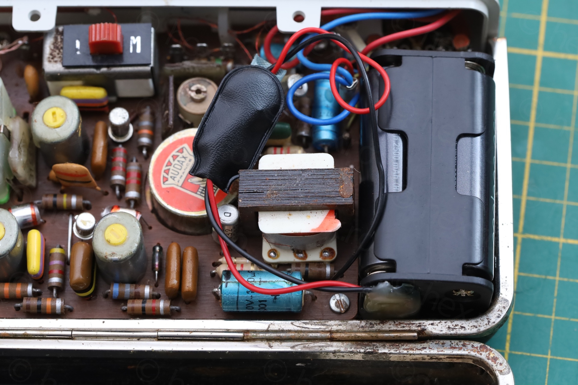
The height of the battery connector is 28mm and playing with it for a while, I discovered that there is a single way to have it inserted: with the snap connectors towards the bottom of the radio, and sideways:
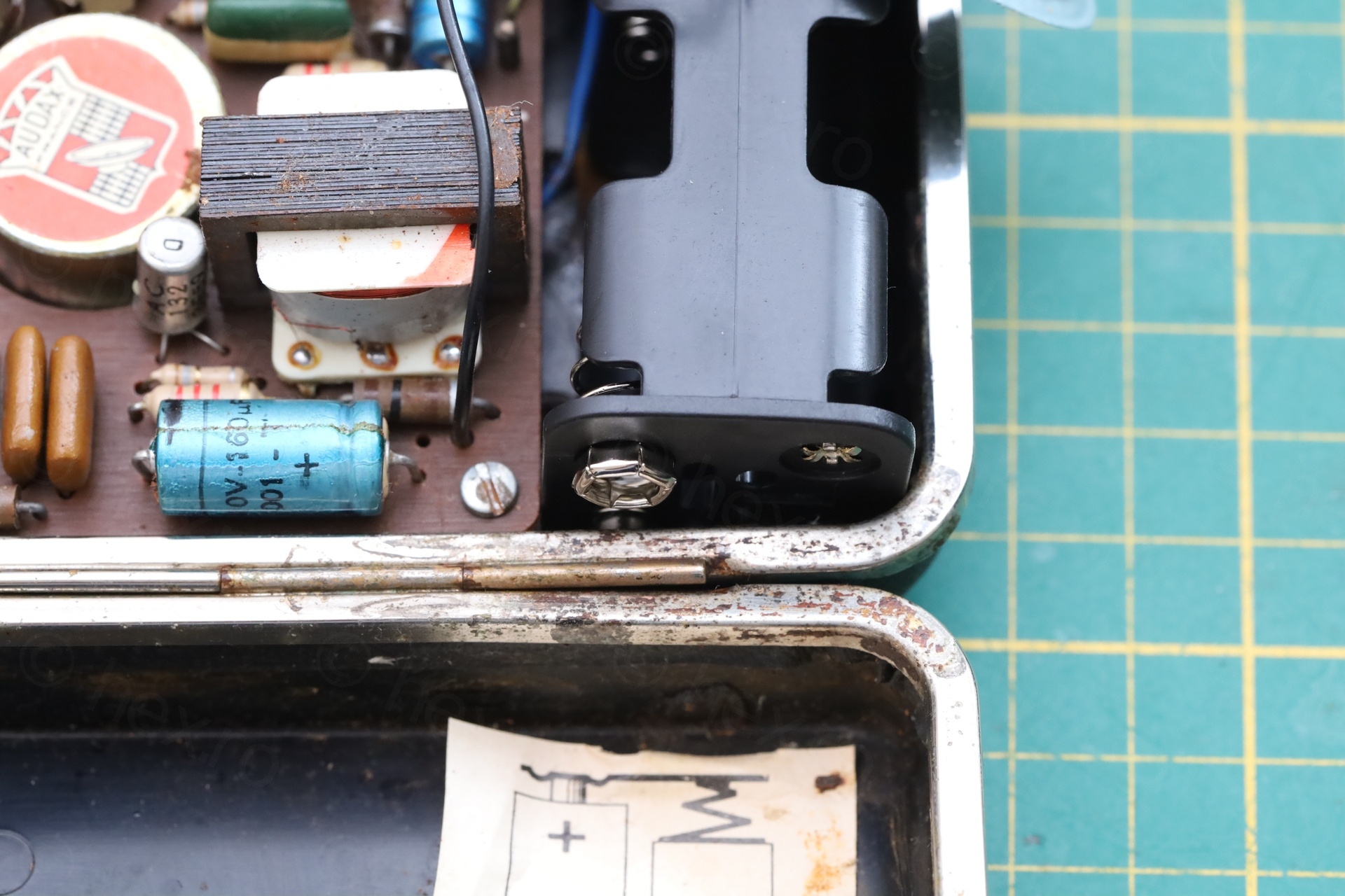
Thus, I should have ordered battery holders with wires directly, not with snap connectors …
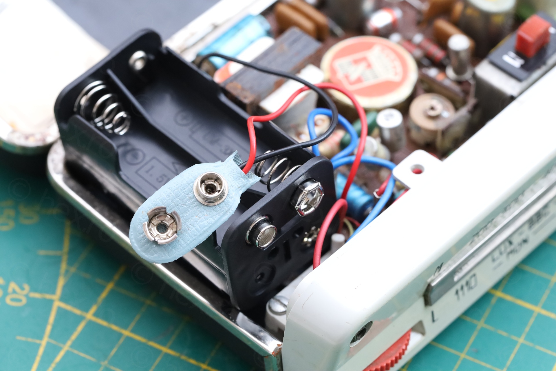
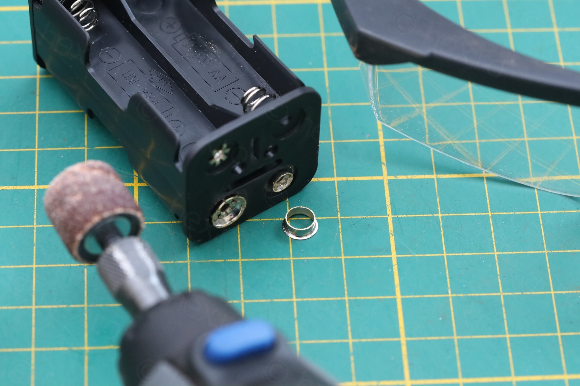
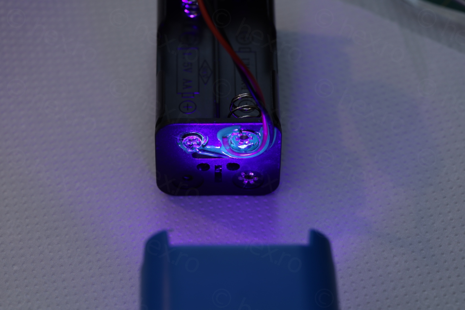
I had to improvise. First, at least eye-ware protection is needed, as I discovered while shaving the snap connectors, one metal ring flew off. I wanted to shave those connectors to have place to route the extension wires. Then, I used UV curing solder mask to keep the new battery clip leads in place, then hot melt glue to prevent possible shorts:
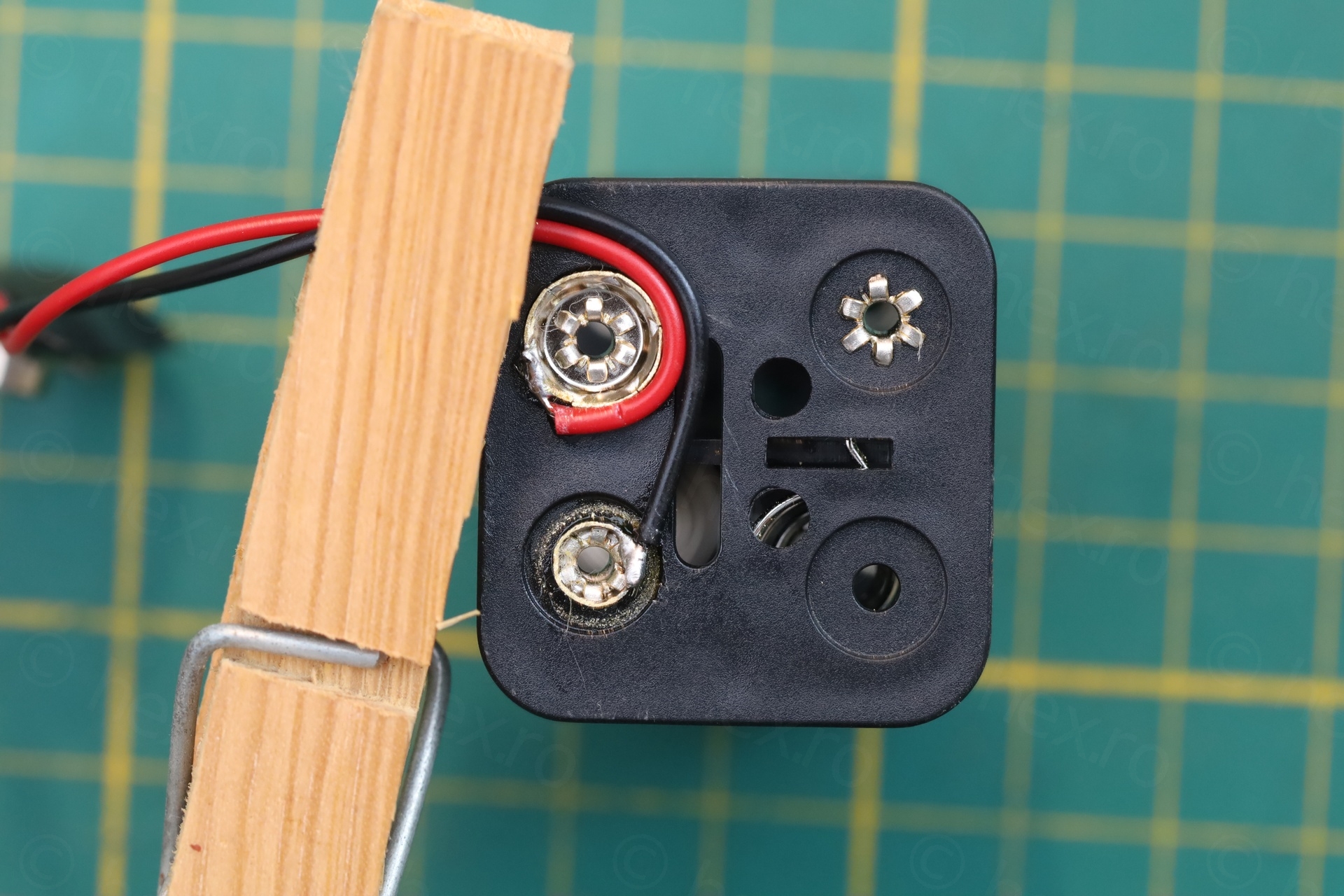
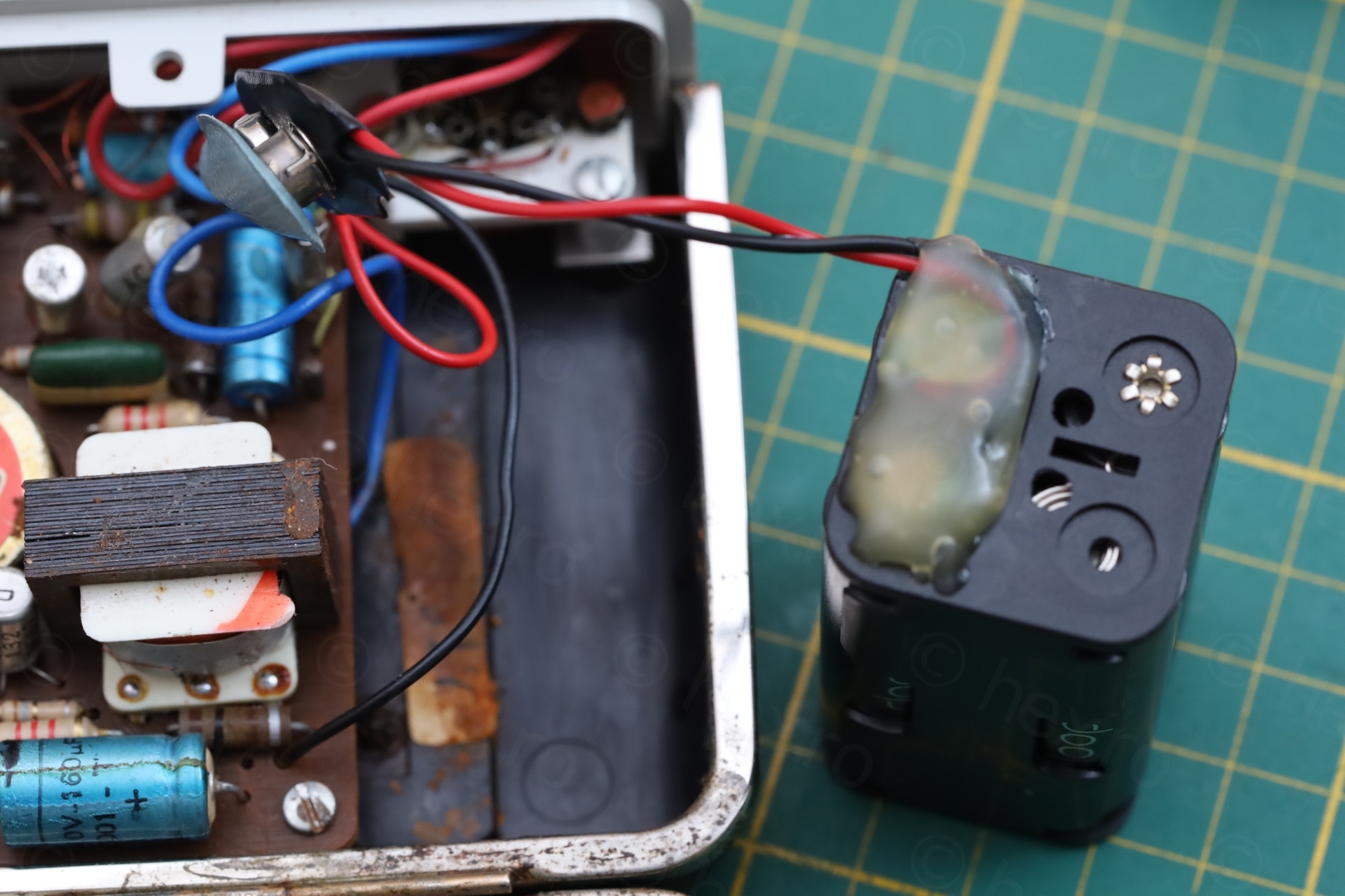
There is a catch when extending the battery holder with a battery clip. The red wire of the battery clip has to be connected to the negative of the battery holder – this way the battery clip becomes an extension of the battery holder. I could then plug the existing radio battery clip into the new battery extension clip – and preserve correct polarity:
If I ever find a battery holder that fits, the original of the battery clip in the radio can still be used – there is nothing irreversible done. If I find a smaller battery holder, I can just replace my improvisation.
Other observations
- There is somewhat of a problem with the voltage on one of the transistors. I didn’t write down which one, was it on the collector of T6 ? Other voltages were fine. I didn’t feel like swapping transistors, radio still has plenty power..
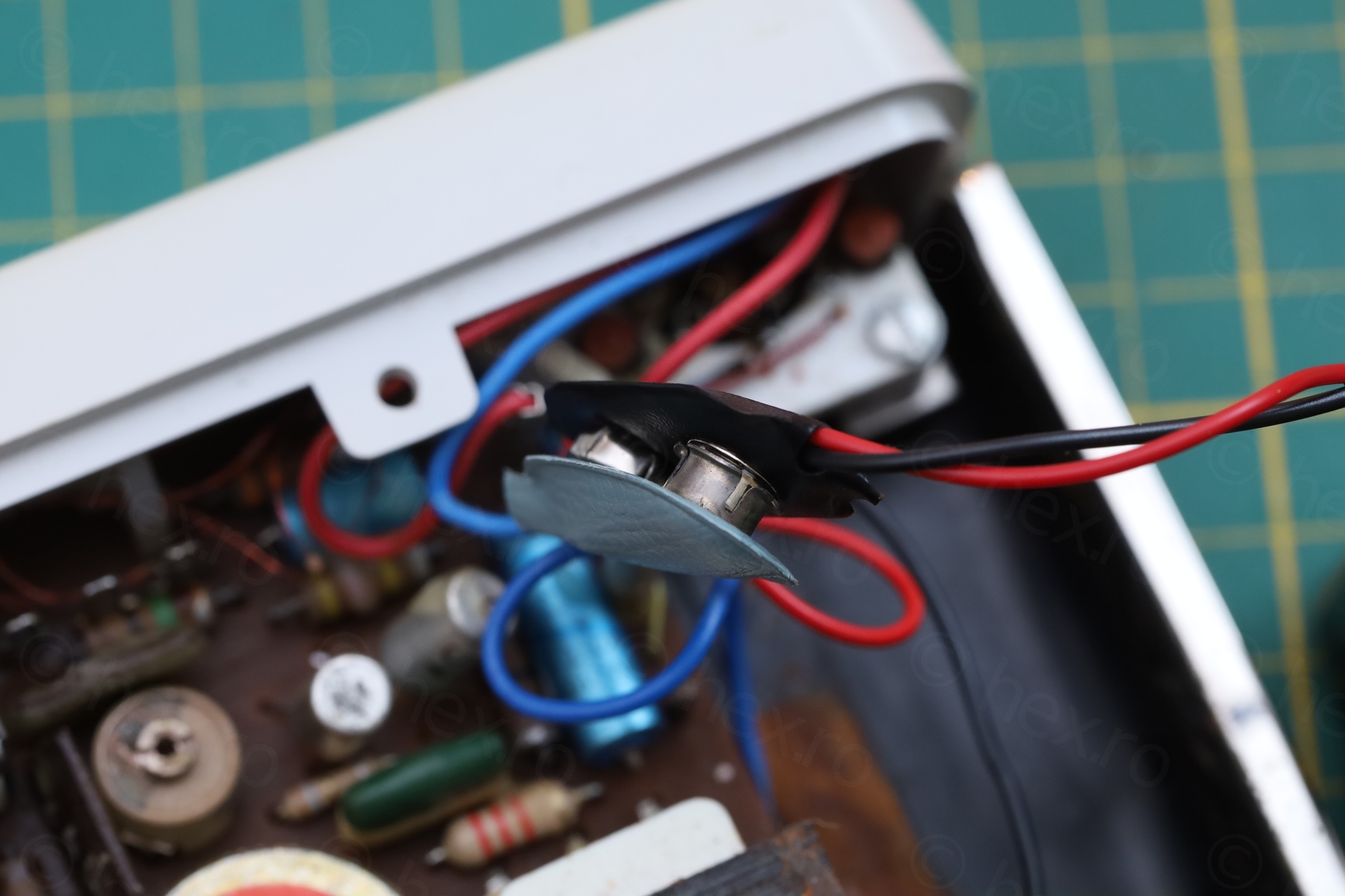
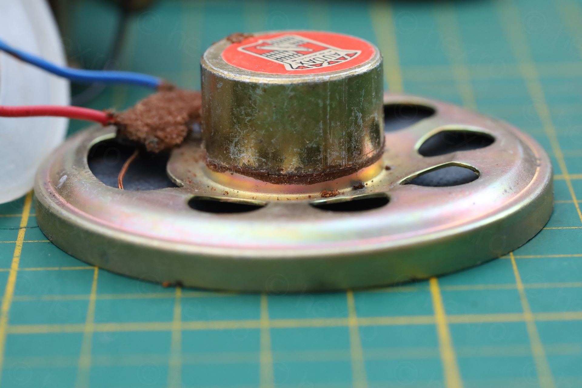
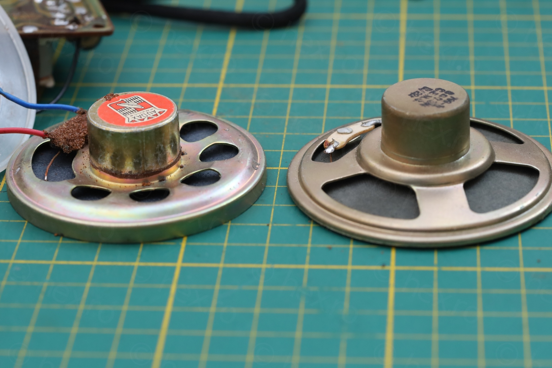
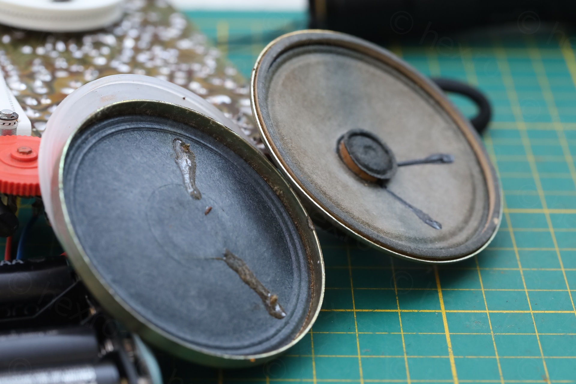
- Speaker basket is “pushed in” and looks damaged, especially when looking at it side by side with a different speaker but it looks it was designed / built this way. I can’t find other photos with this speaker, only of other St Gilles radios. Where, the speaker magnet seems to stay at the same height (through the circuit board) as this one does. It seems that they were purposely built like this, to squeeze the speaker basket between the front grill and the circuit board. The good news is that it still works, and I don’t need to replace it.
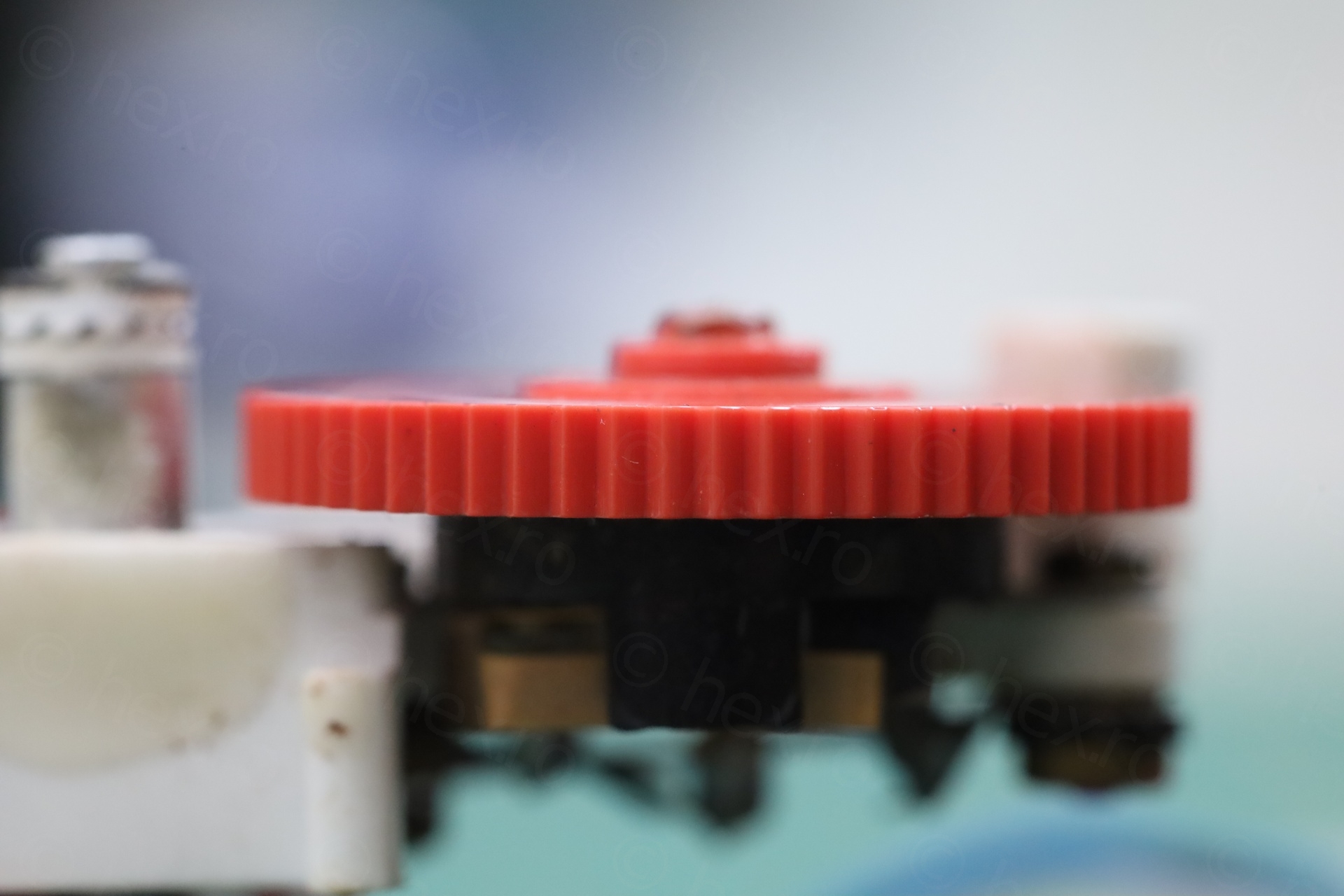
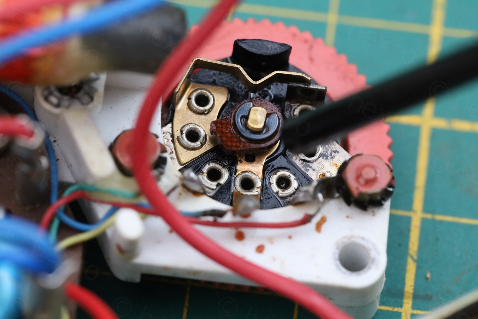
- There was also a bit of a problem where the volume knob was scratching against the case. This was fixed by slight adjustment of the circuit board when during re-installation. The volume pot and the band switch got a bit of a contact cleaner, to make sure they last longer:
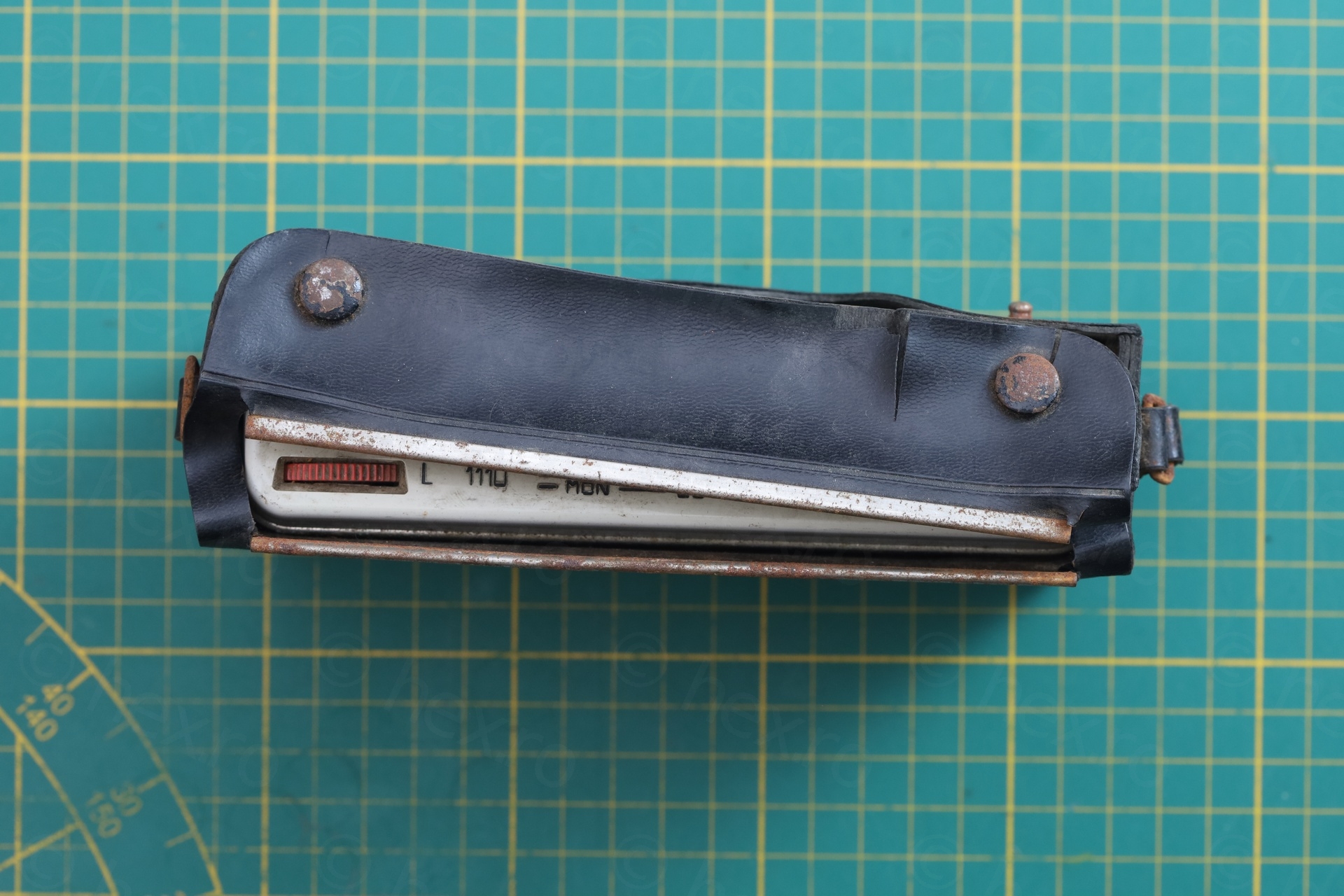
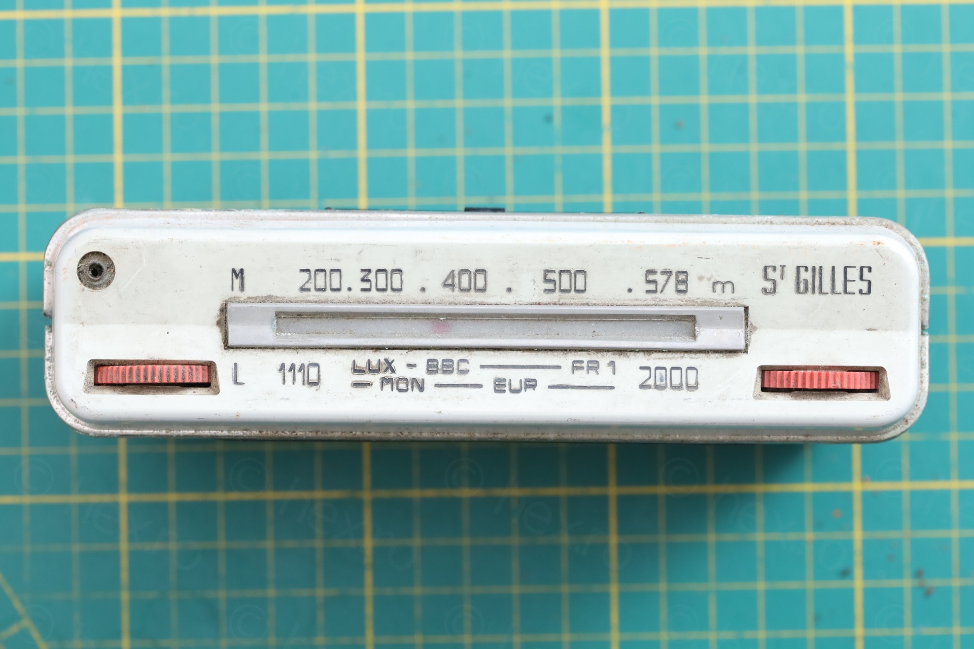
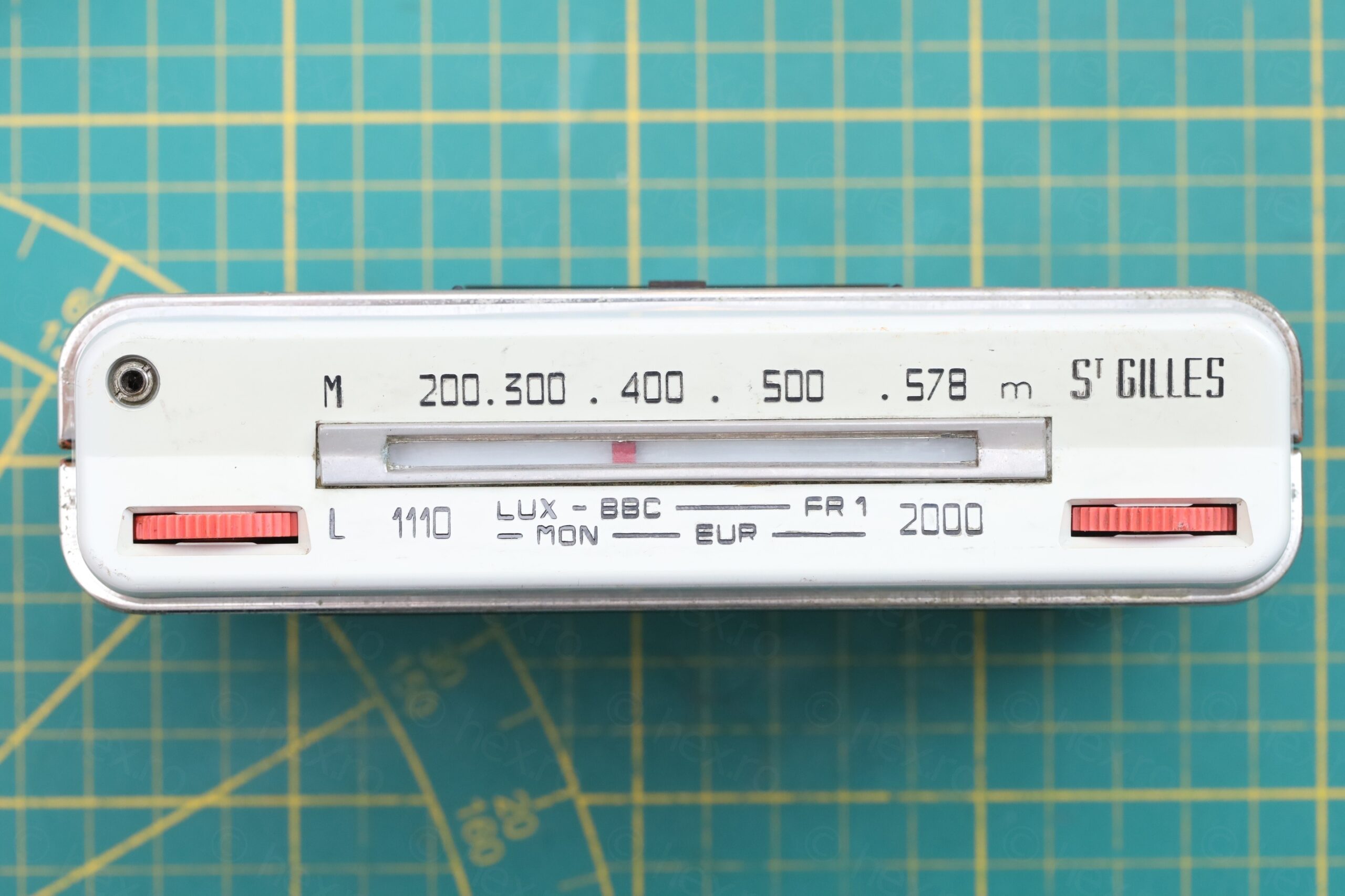
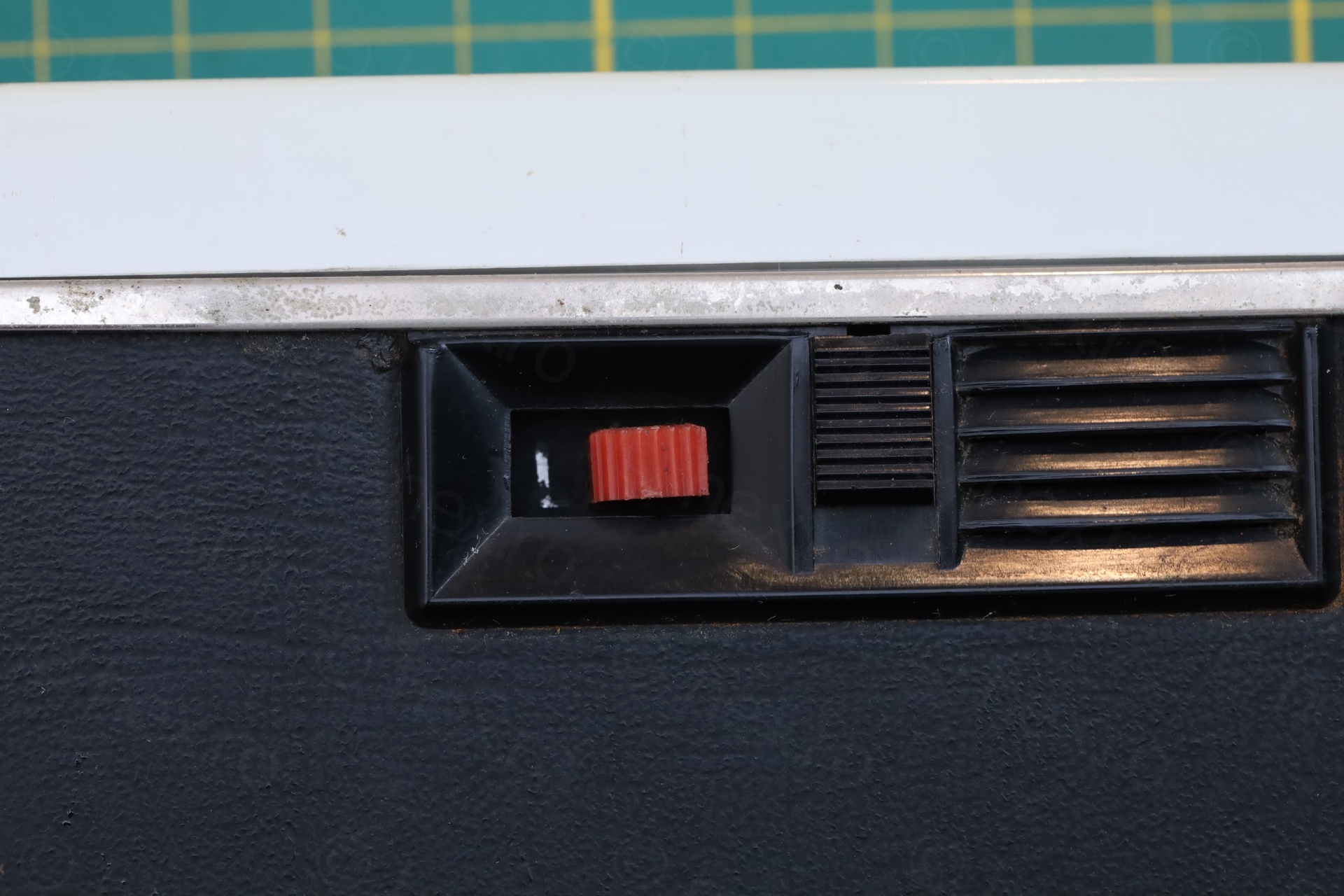
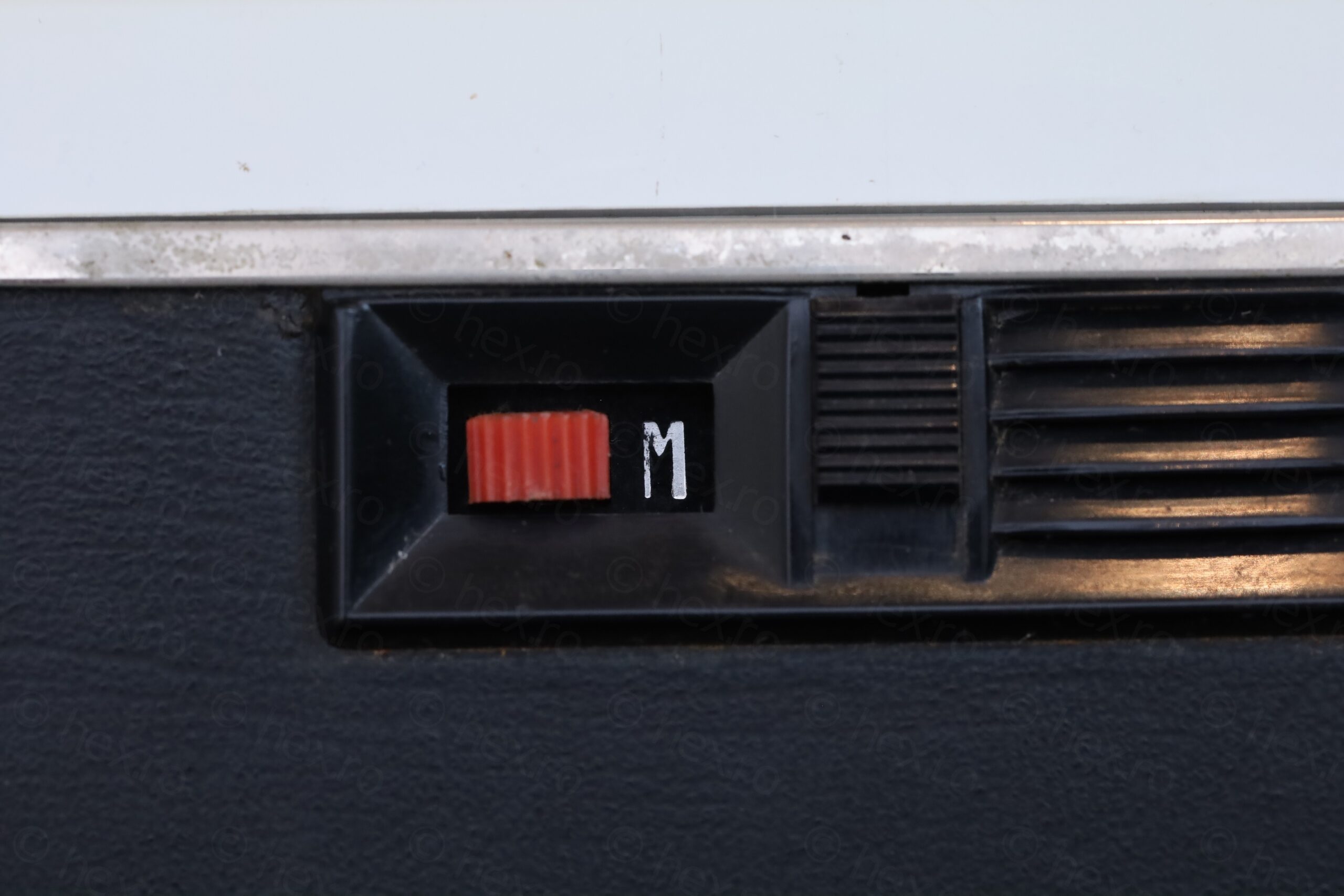
- While the radio has the L and M markings for the two bands, it still uses the old notation where the dial indicates the wavelength of the signal and not the frequency:

Tests
Band scan, both AM and LW – watch out please for cracks / noises, if you use headphones. It works 🙂
Leave a Reply