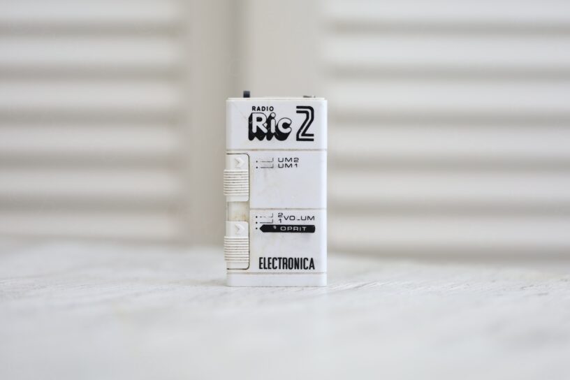

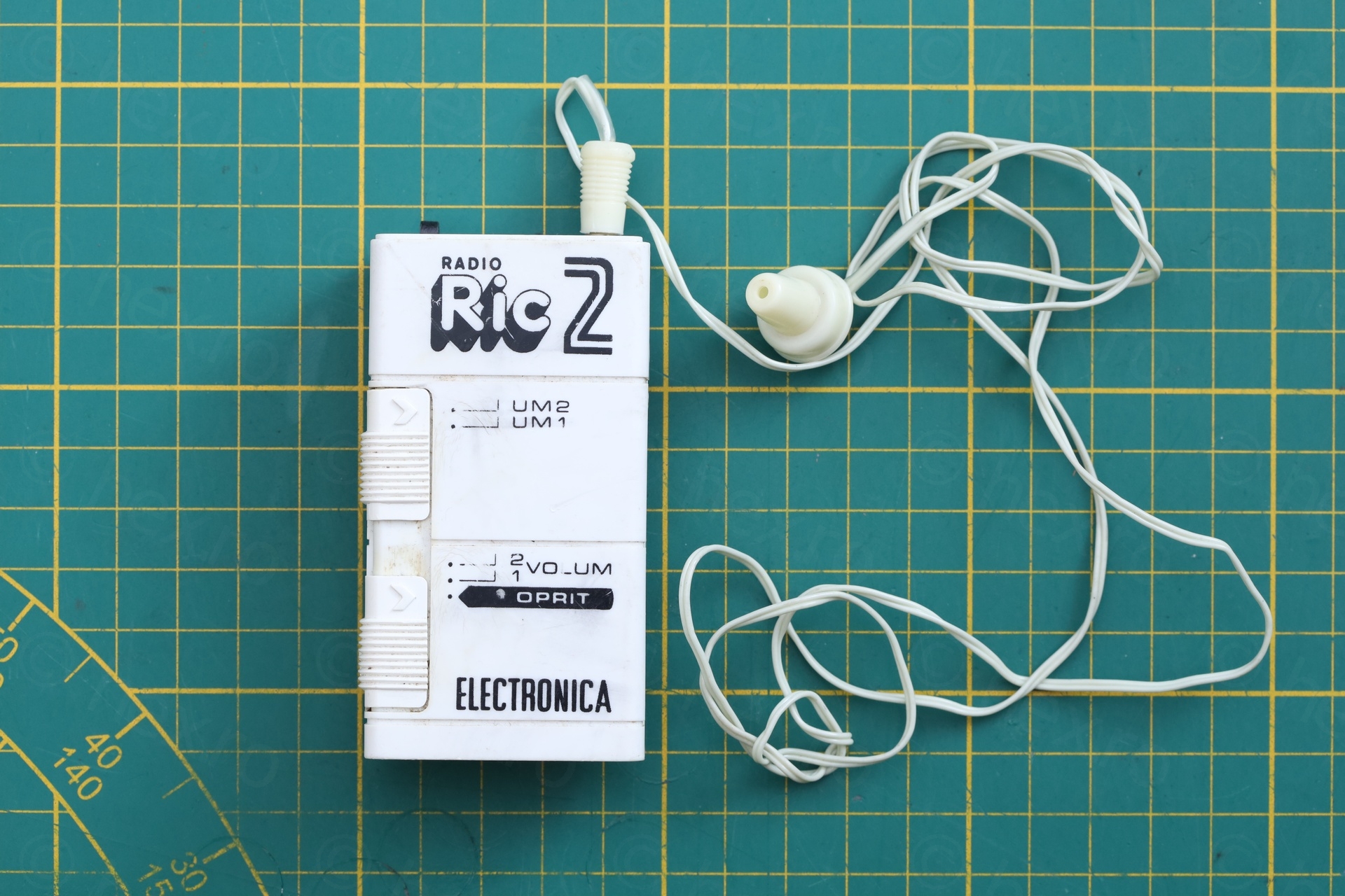
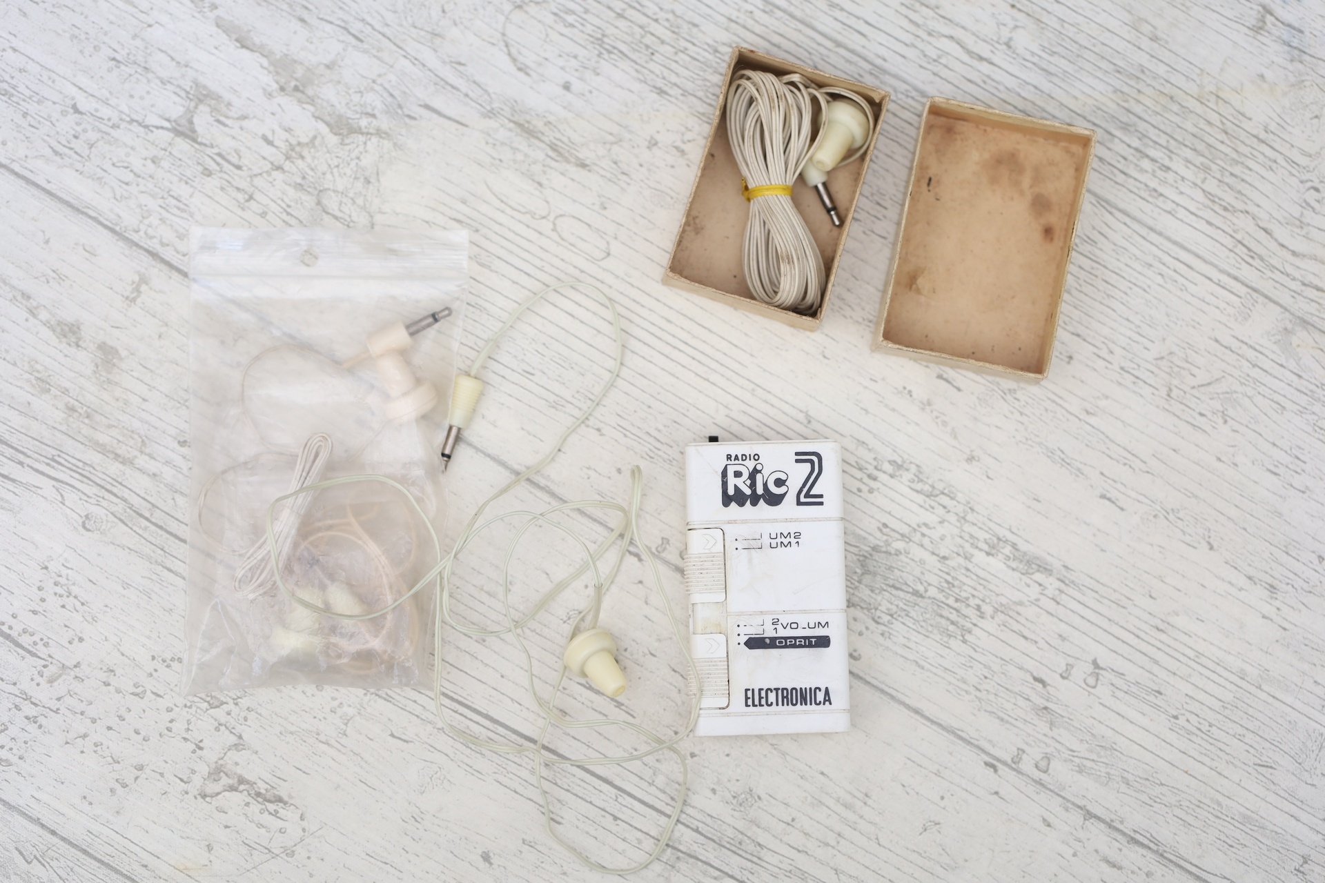
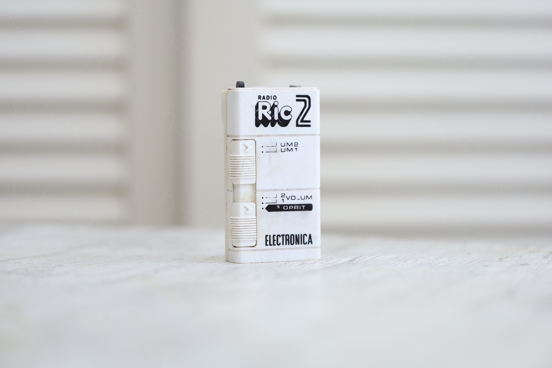
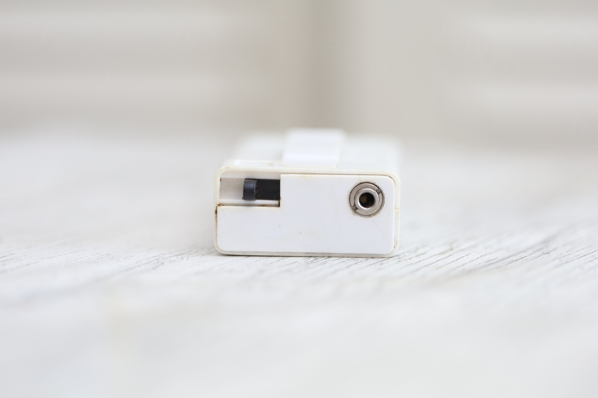
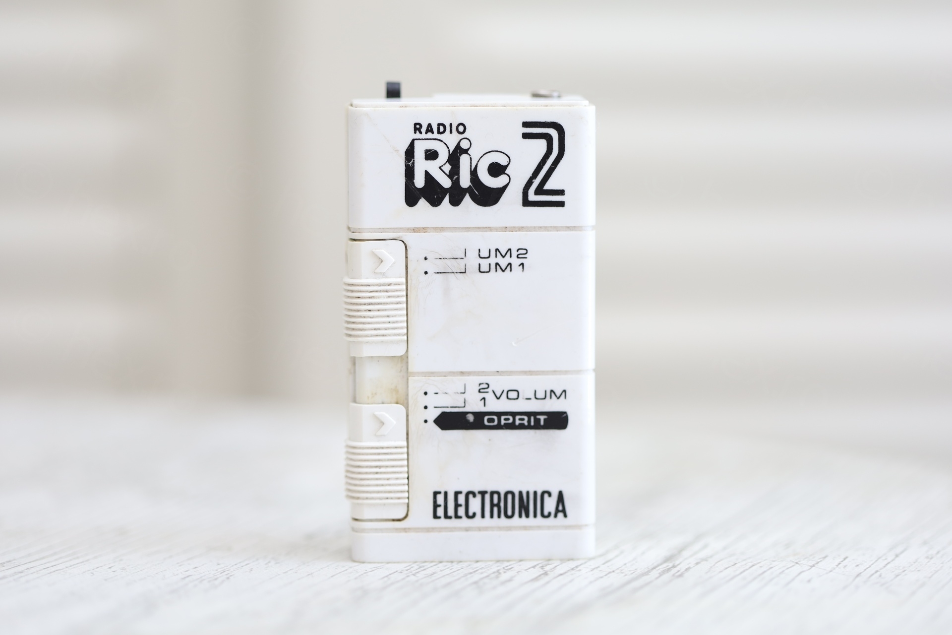
Found this radio at a flea market in Bucharest, the seller justifying his “low” price on account of a “wire being loose” inside. I had a quick lock inside, all parts seemed to be there (although the radio looked very bad inside) and purchased it.
Table of Contents
- Introduction
- Having a look inside
- Visible Problems
- Re-enforcing the inductor
- Figuring out the circuit
- First power on!
- Antenna measurements
- C2 Capacitor
- Corrosion cleanup
- Replacing C2
- Putting it back together
- Some observations / reflections
- Conclusions
- References
Introduction
This radio brought back memories of my childhood. In the early ’90s, these models were on sale along the Black Sea coast during the summer season. I probably owned two of them, but I was always annoyed that the headphones were unreliable—the cable would develop a fault rather quickly. And another episode comes to mind mind: on the beach, I could hear Radio Vacanta blasting from some far-away loudspeakers, yet I couldn’t “find it” on the radio itself. The station was on FM, the radio only had AM, I didn’t understand the technical details – it just felt the radio was a “let down”.
Having a look inside
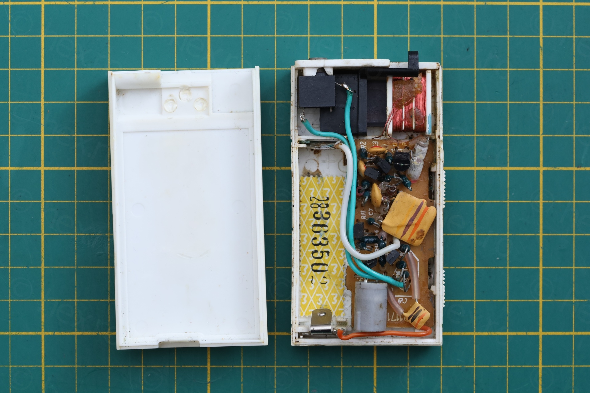
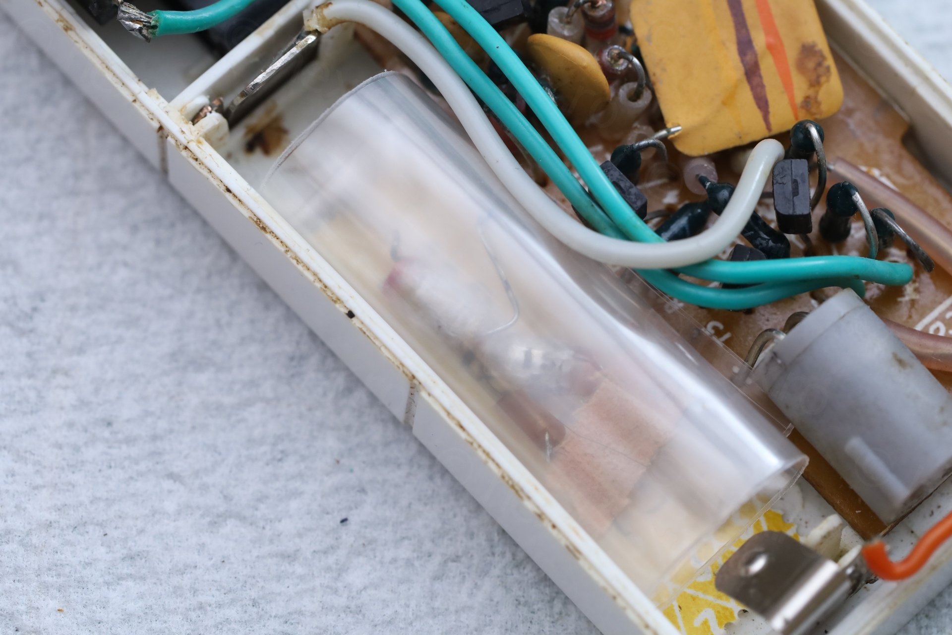
Back home with the radio, I took a long look at it. It had some deep scratches, paint was smeared allover and it was full of corrosion inside.
I proceeded to photograph it as it was:
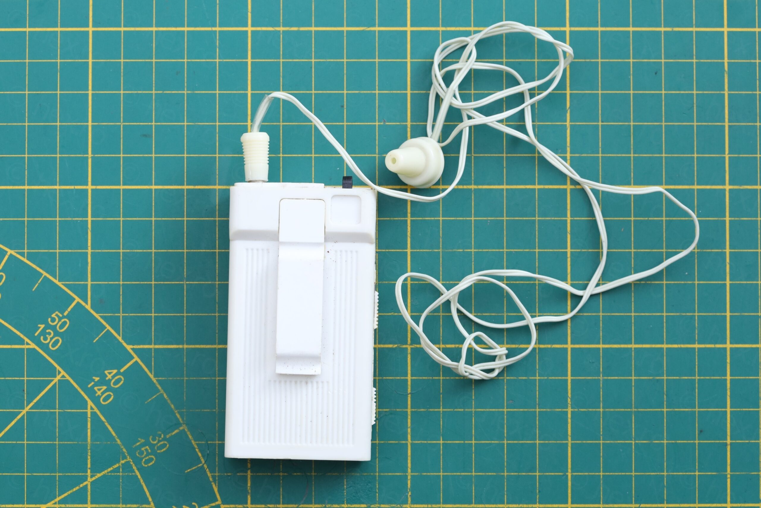
It is helpful to take photos from few angles, might come in handy if some other wire becomes loose. Soon after, I found the problem …
… one of the tuning inductor leads was loose.
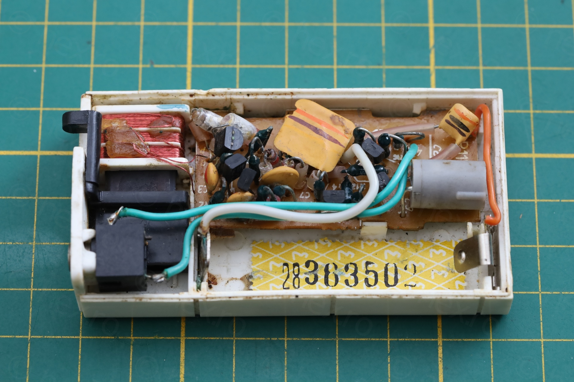
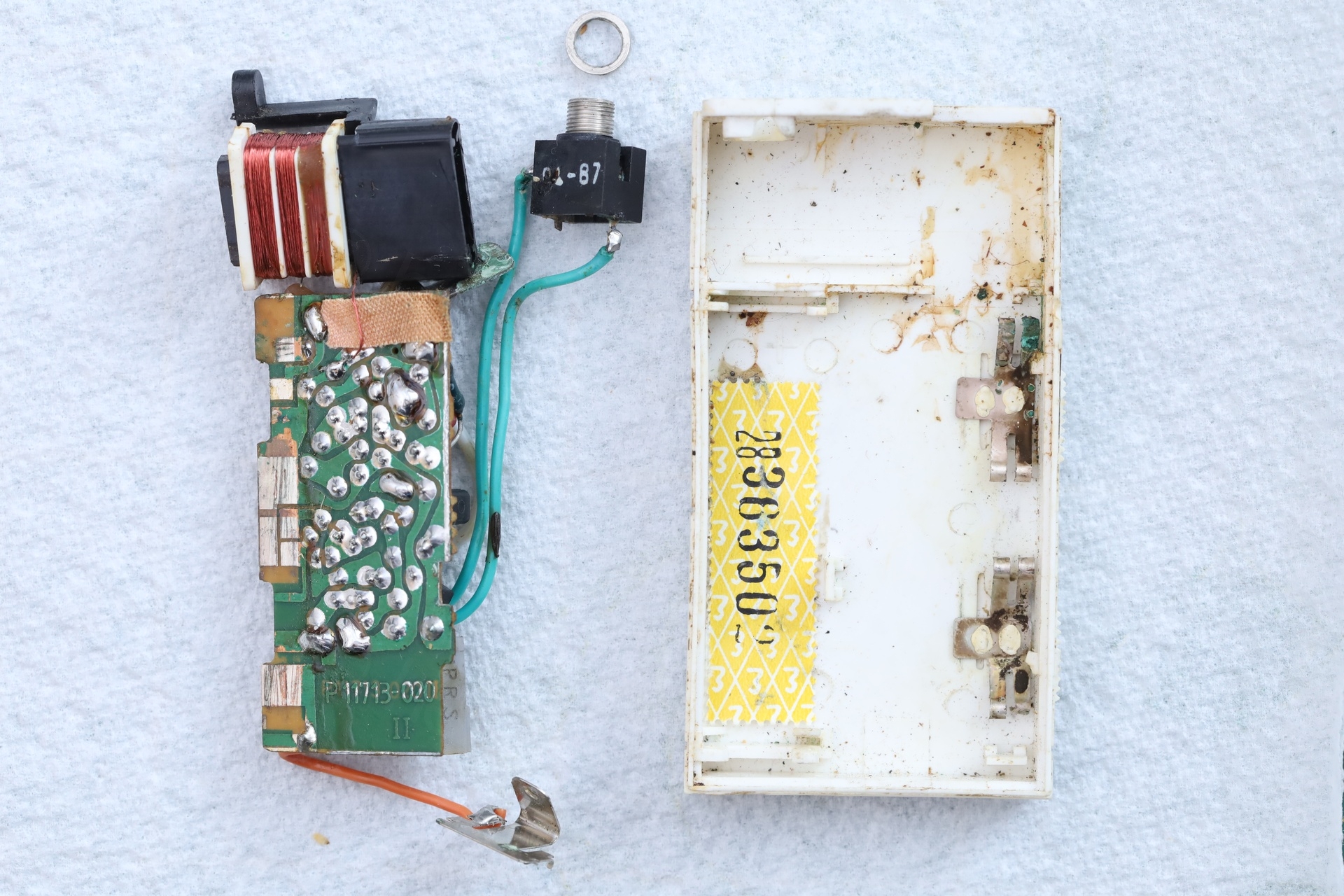
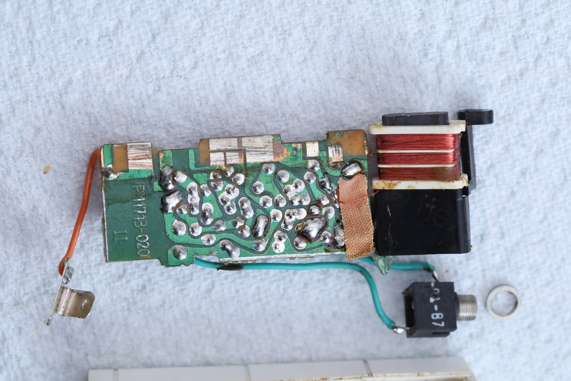
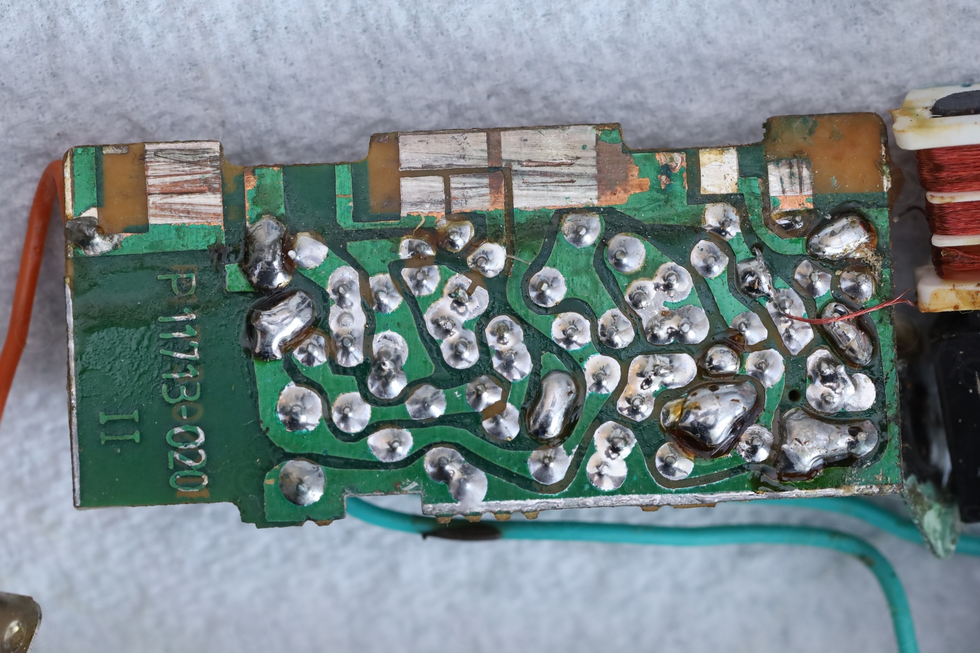
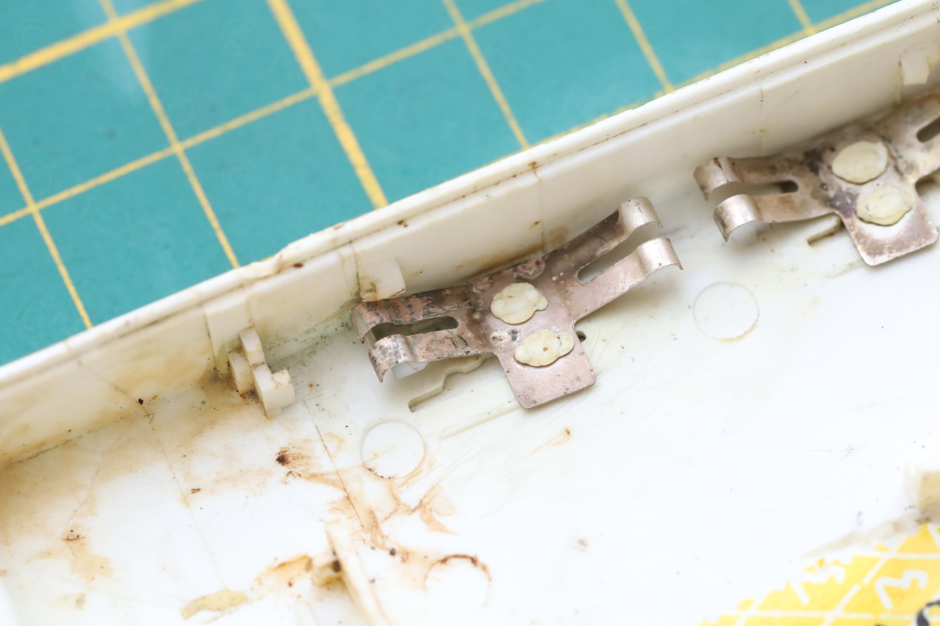
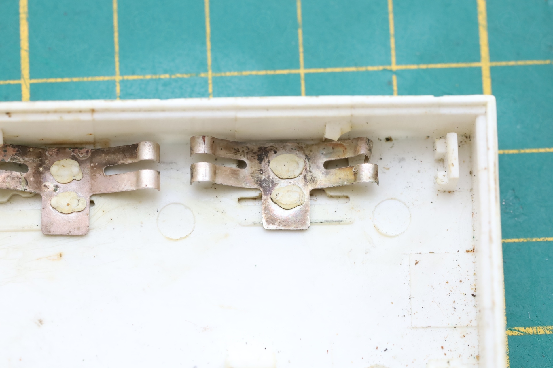
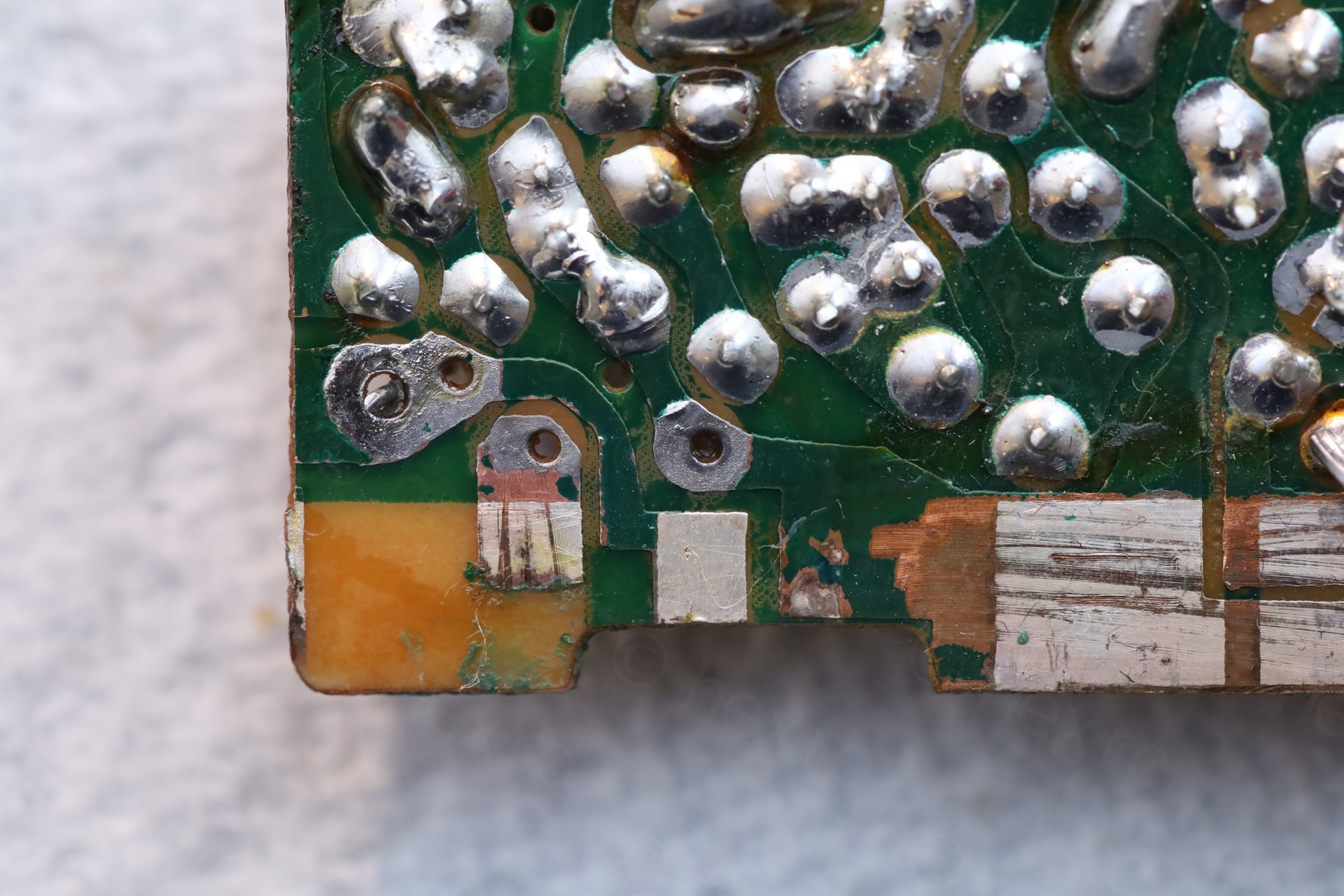
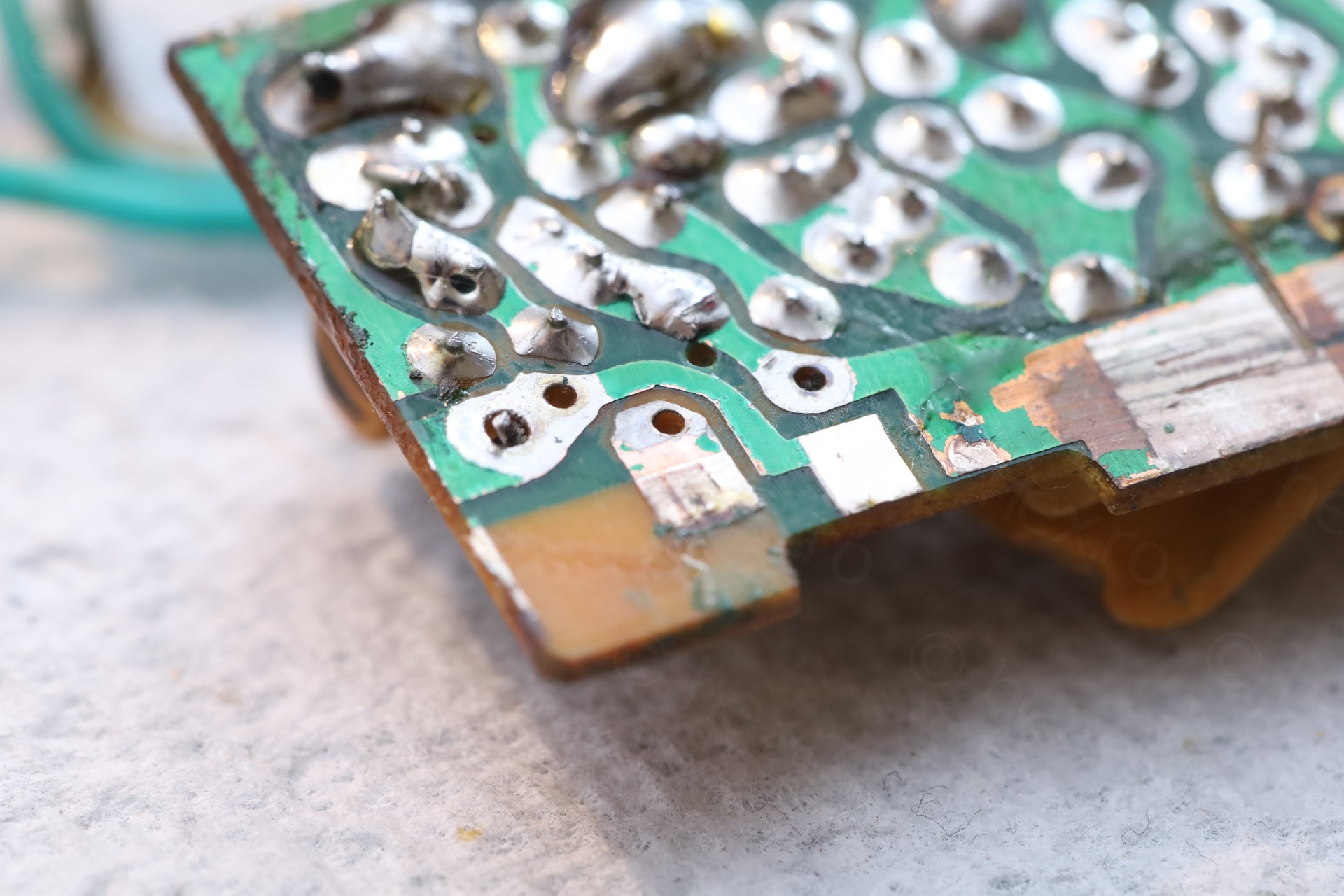
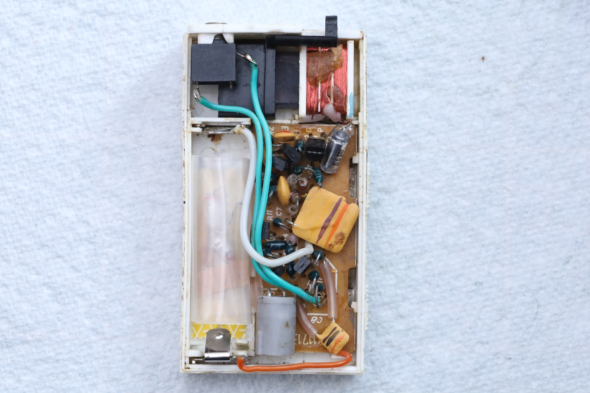
I proceeded to take the circuit board out. The case was very dirty, the blade contacts of the buttons were very corroded, but at least, the soldering looked original:
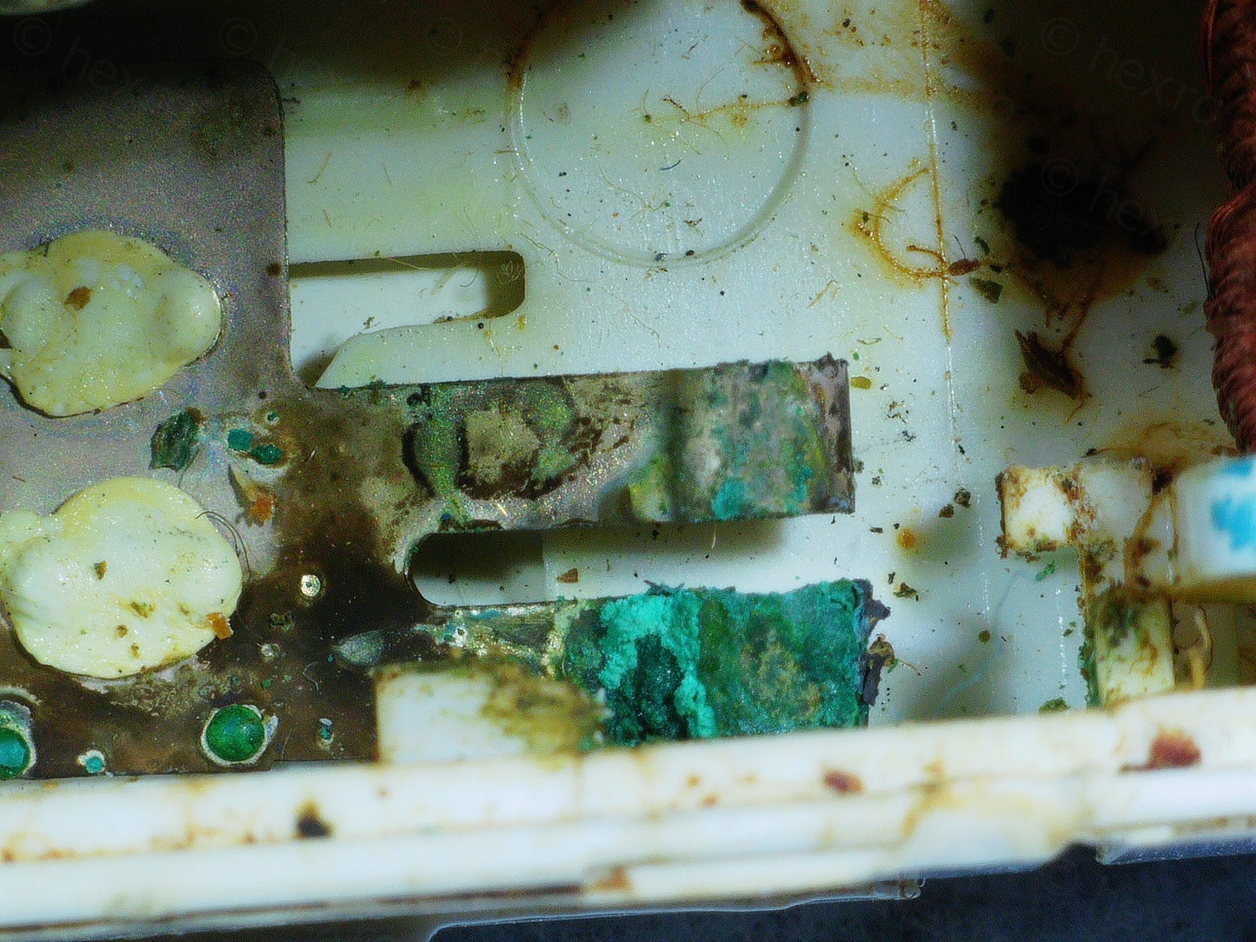
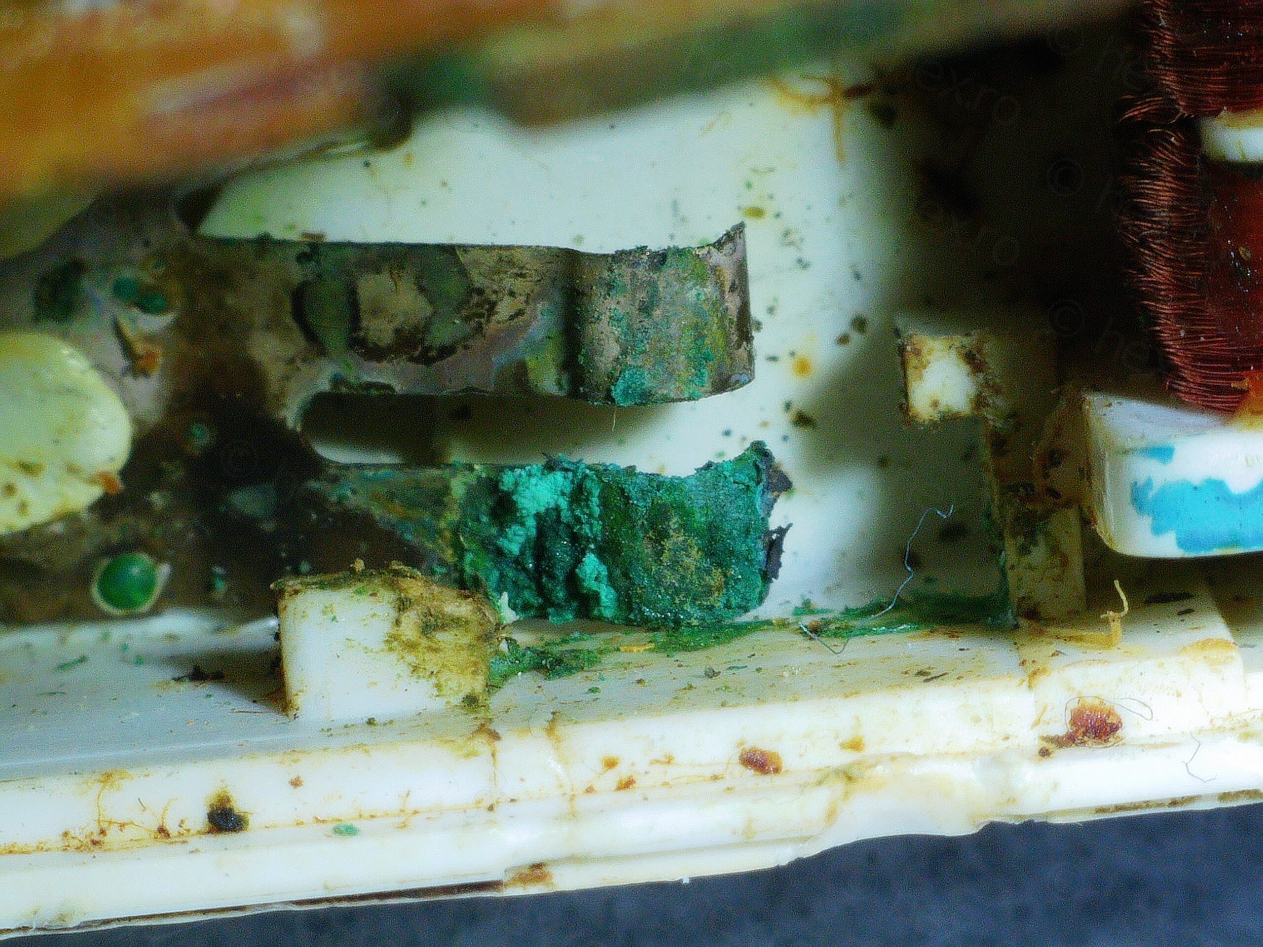
Visible Problems
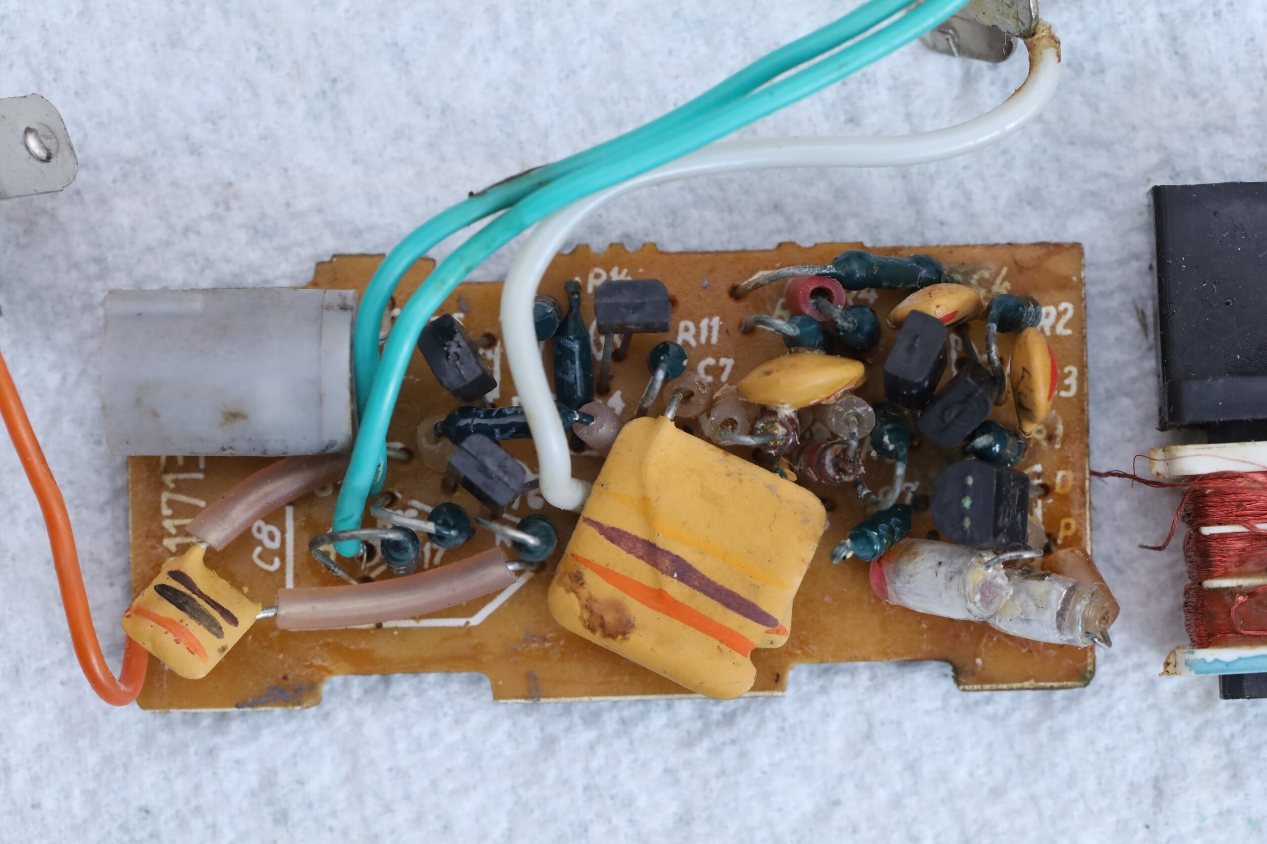
There were many problems to solve.
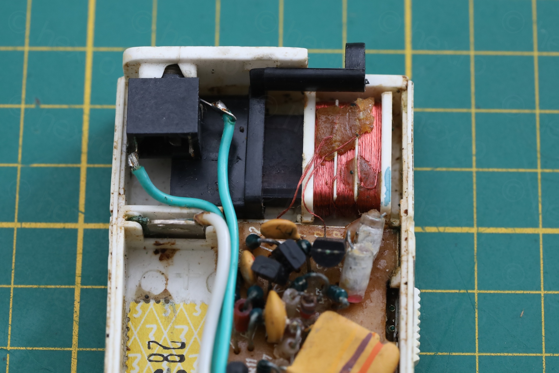
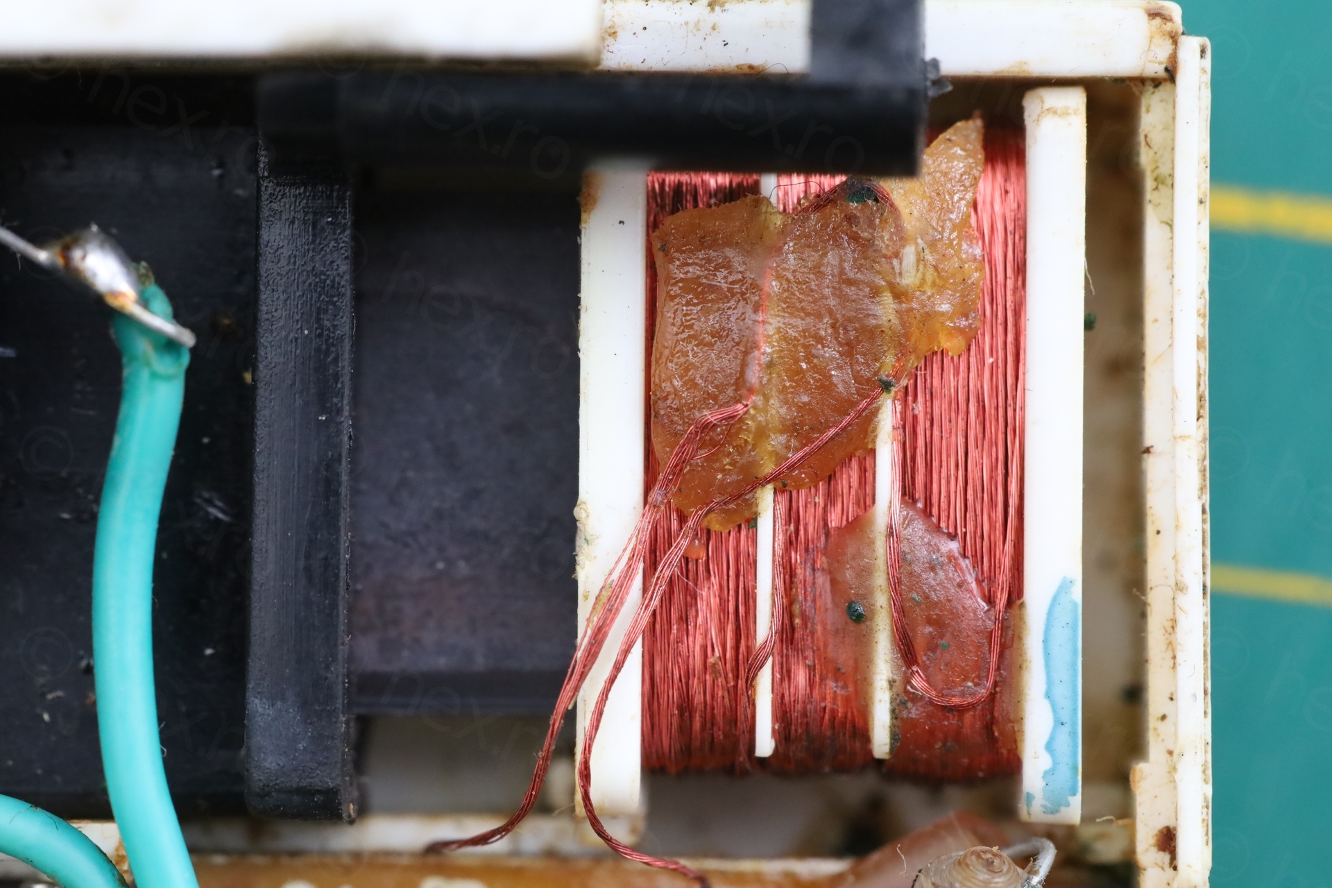
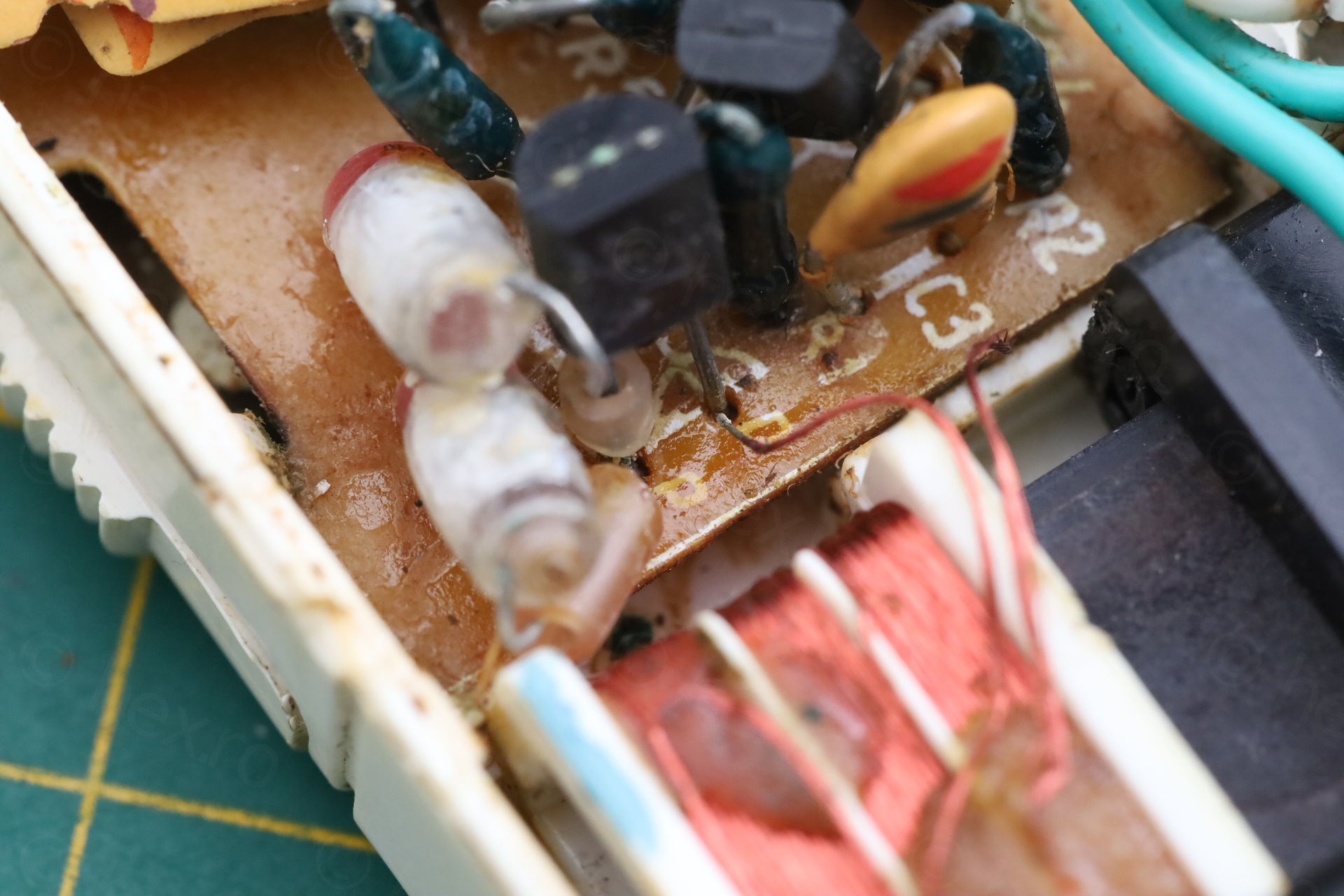
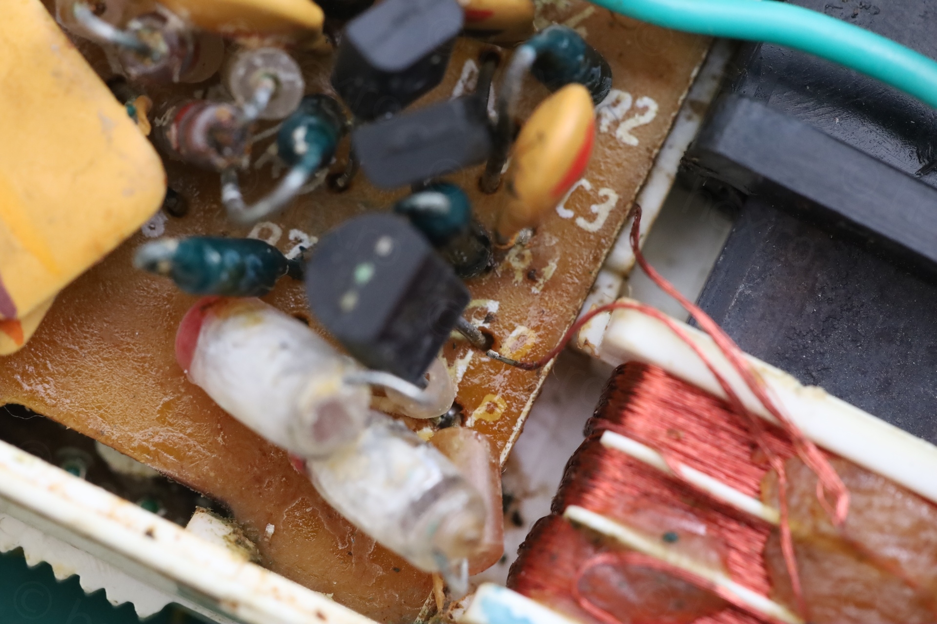
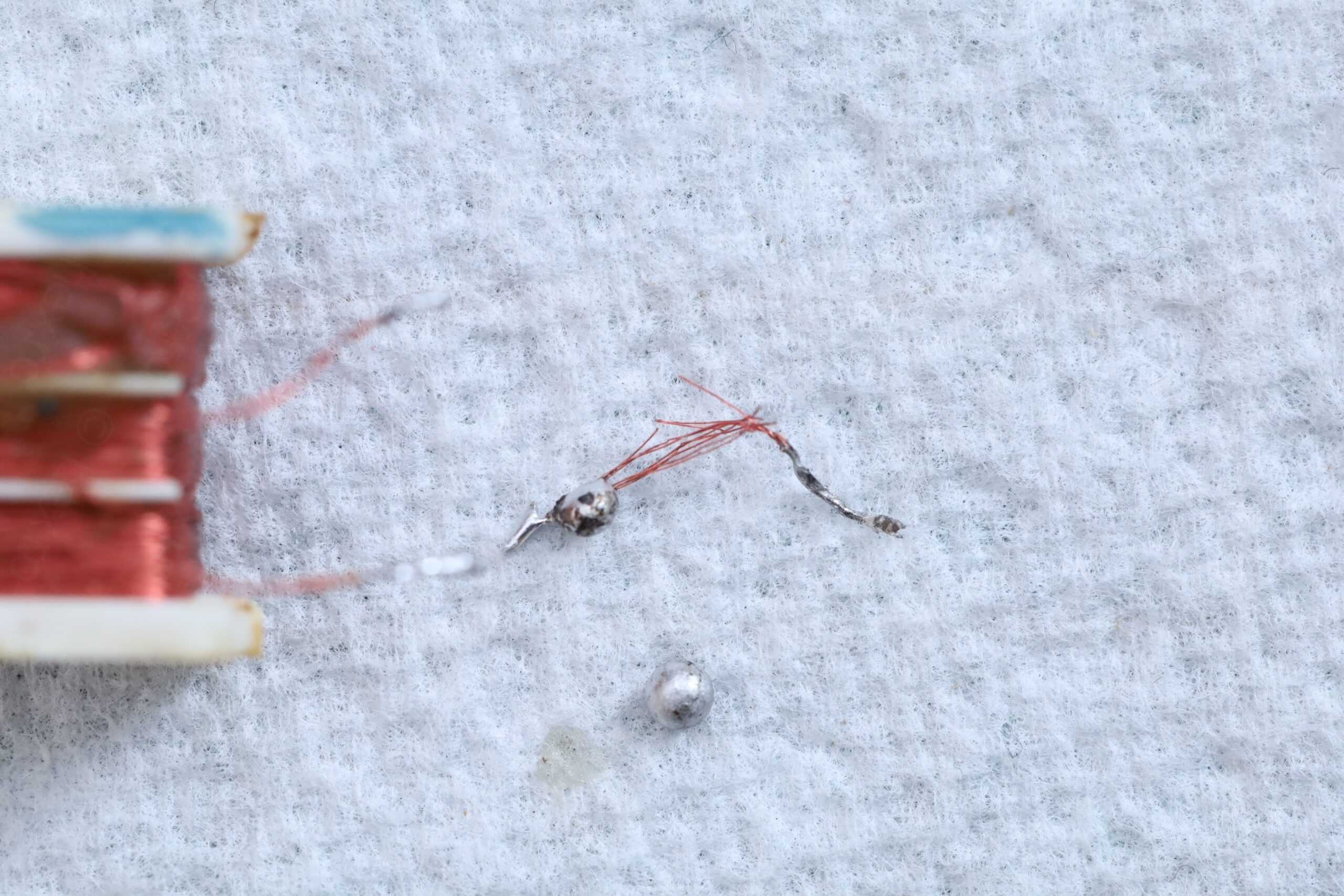
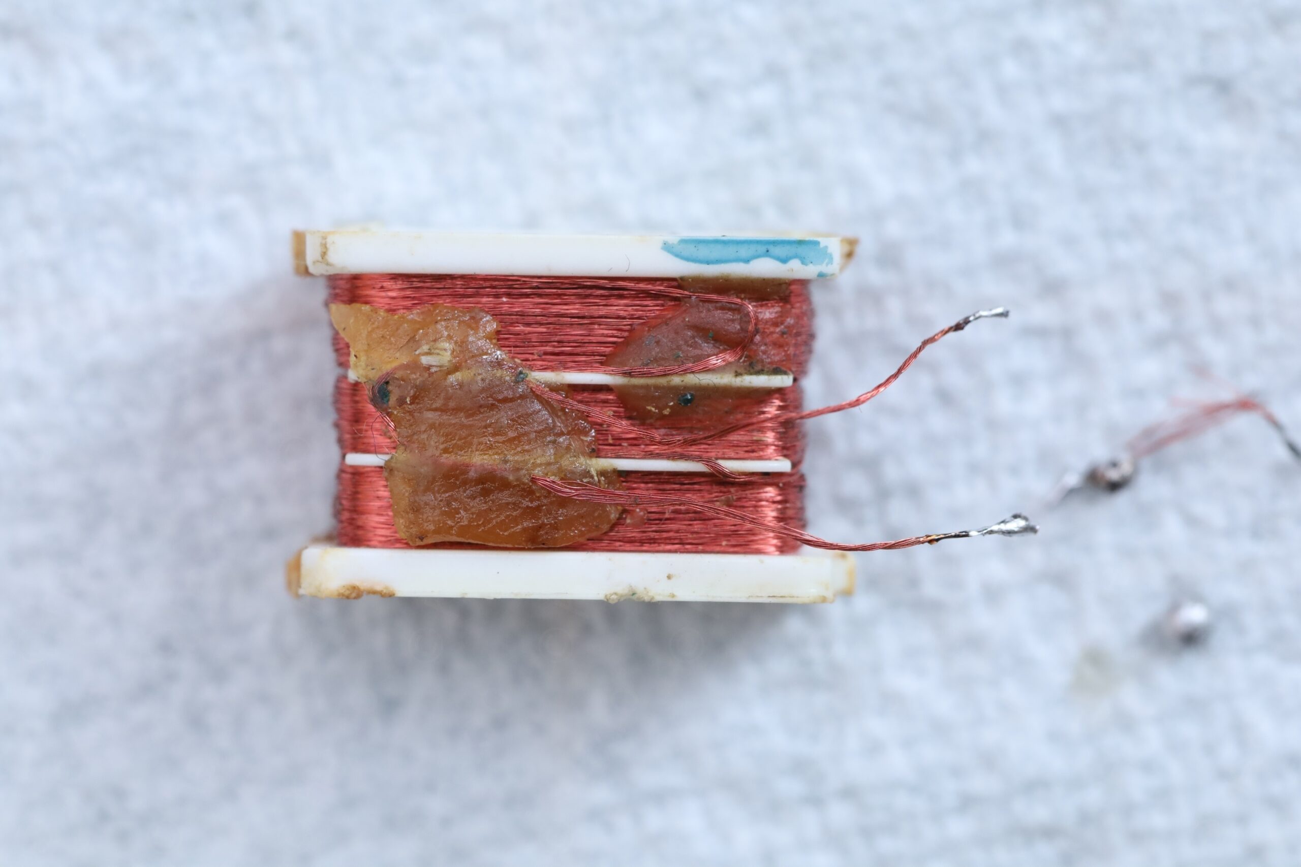
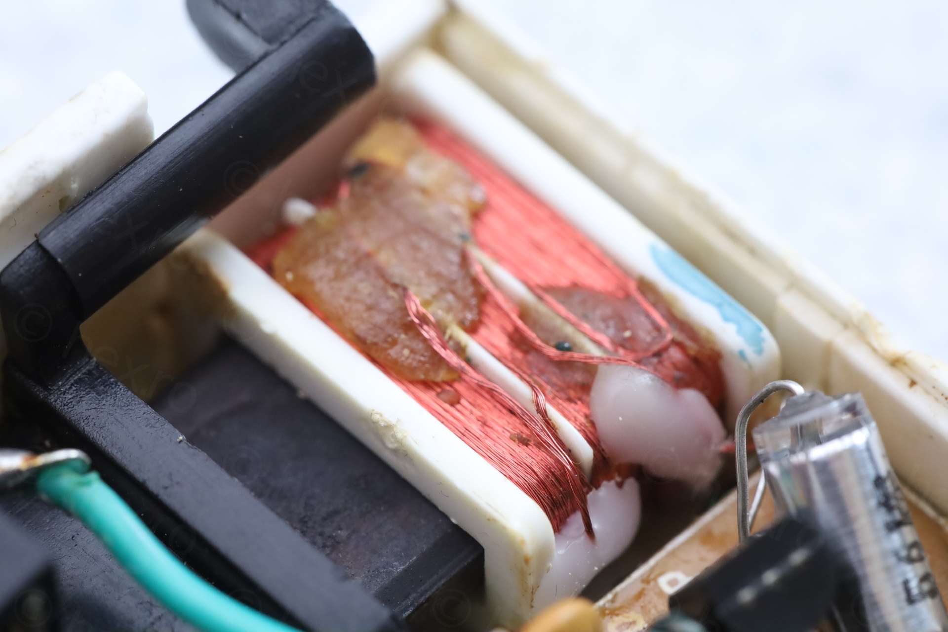
- The inductor wires were frayed, not only the disconnected end, the other end started to fray.
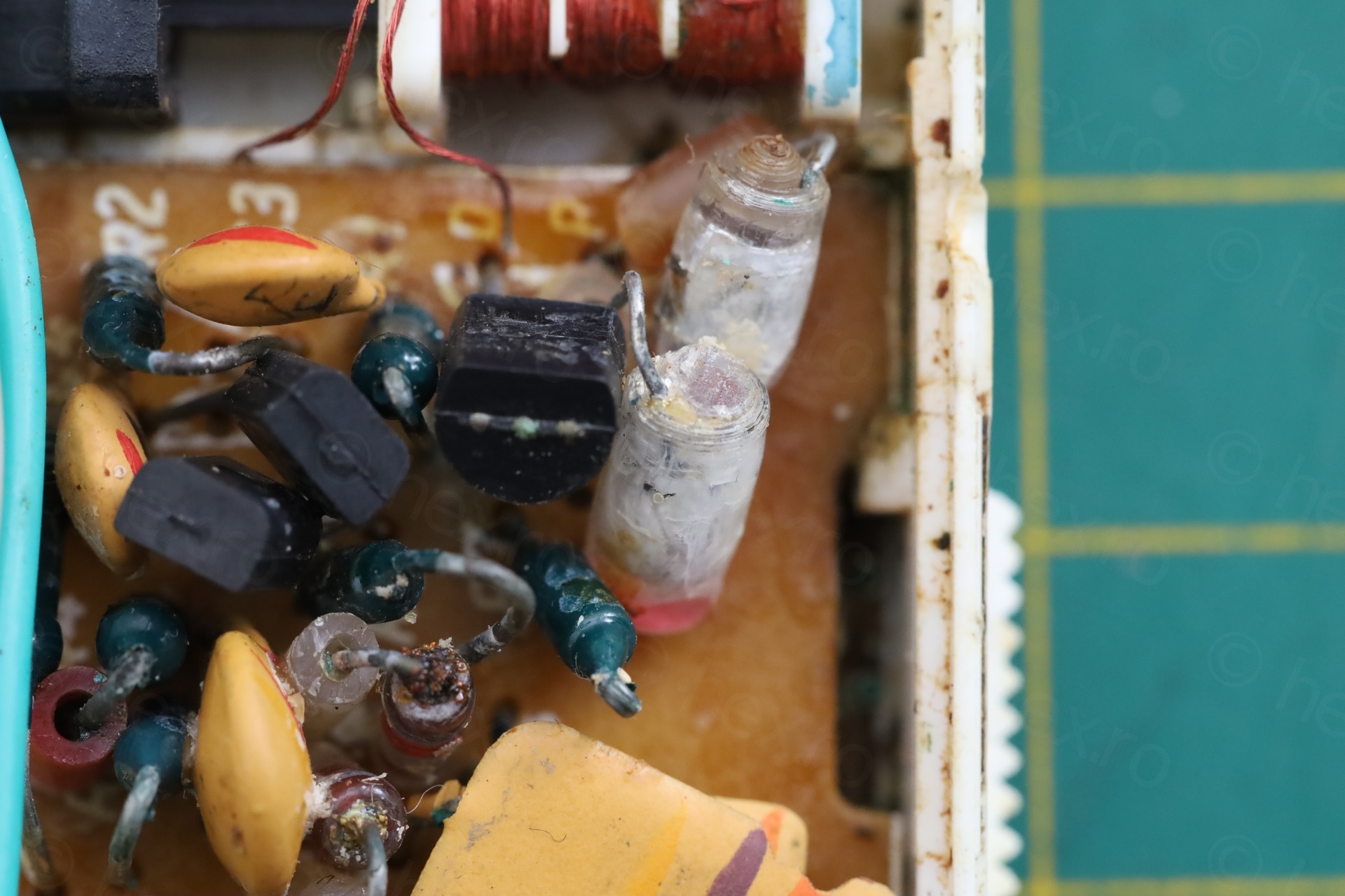
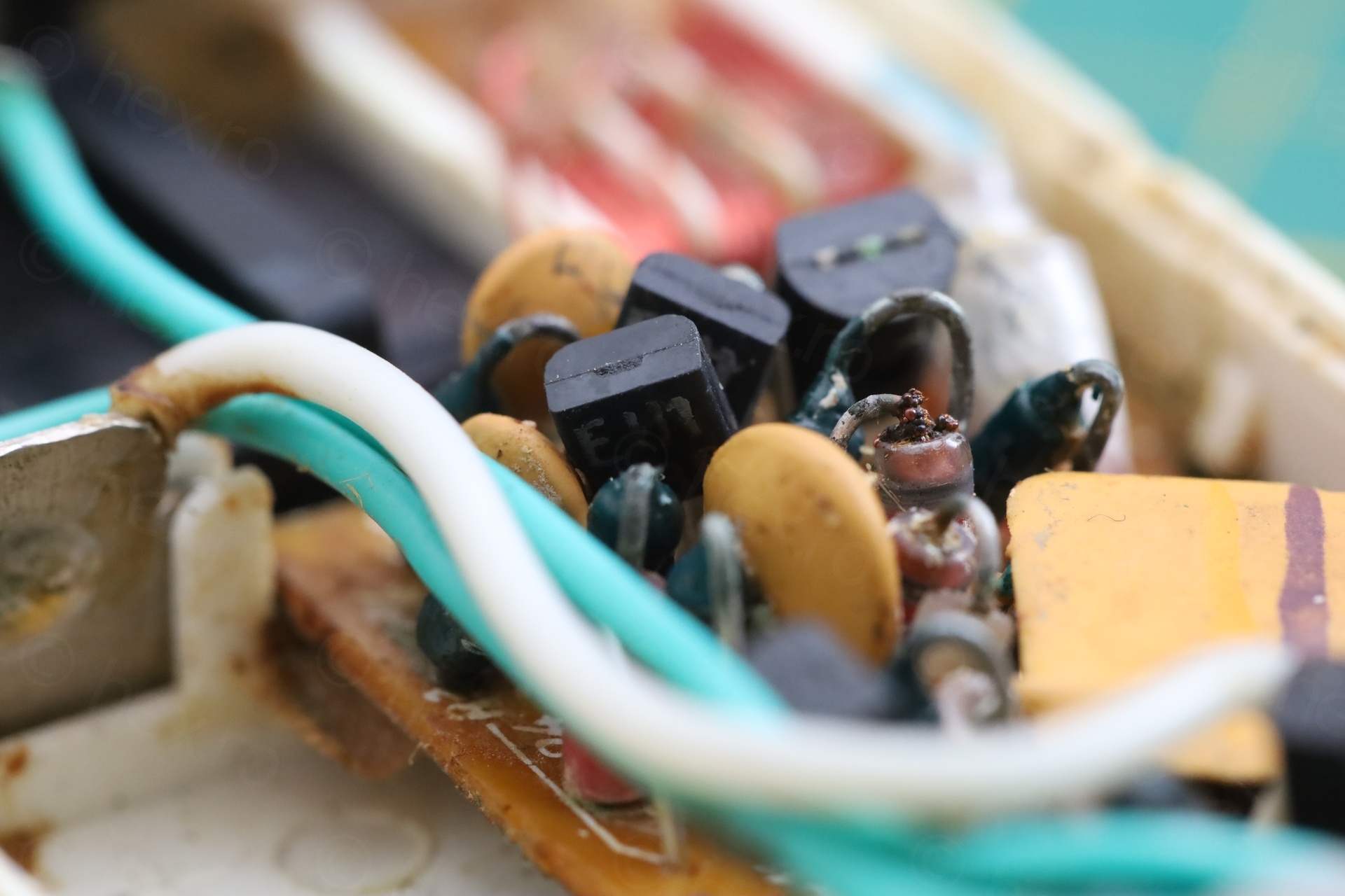
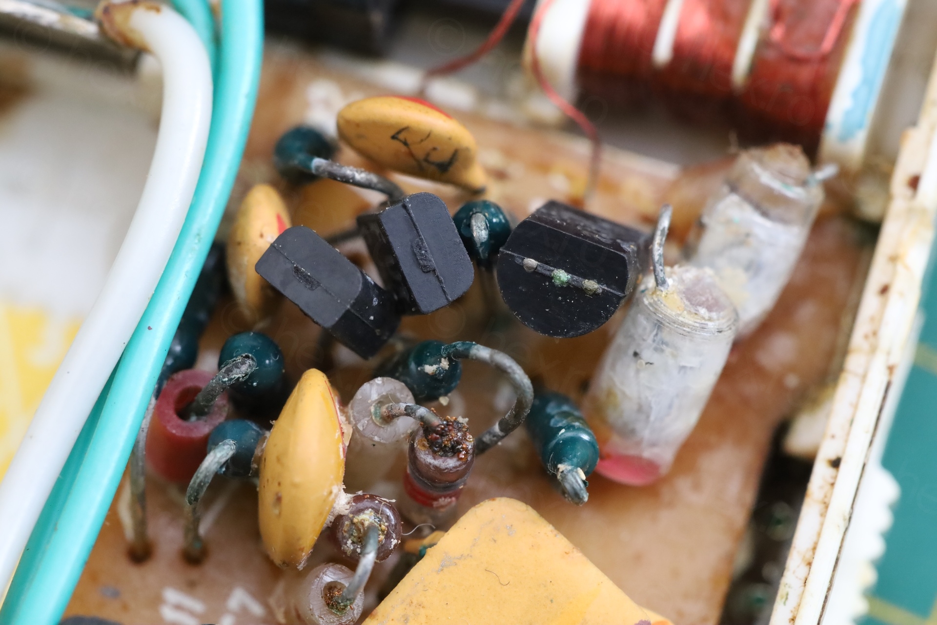
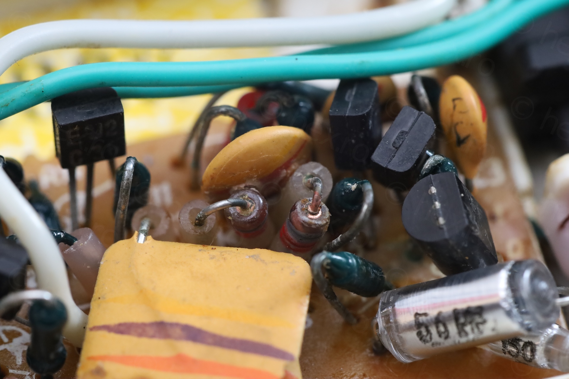
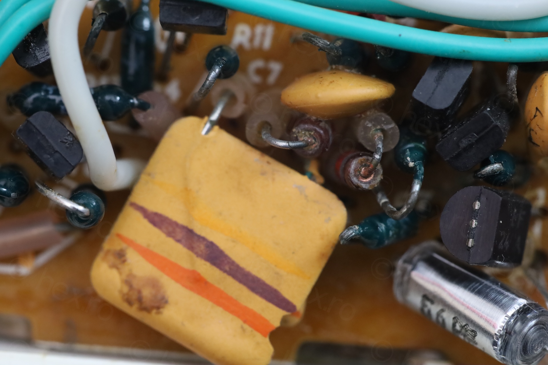
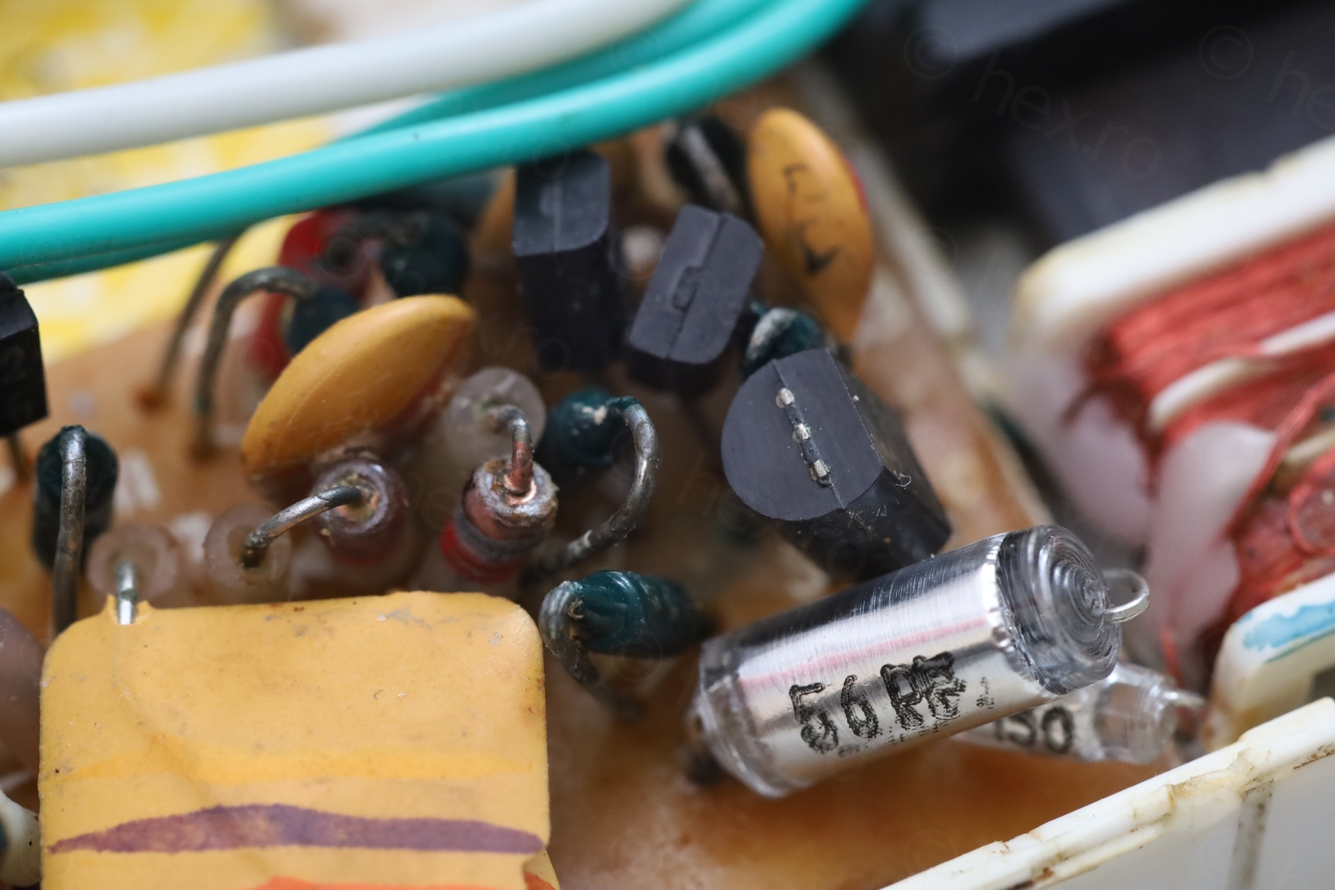
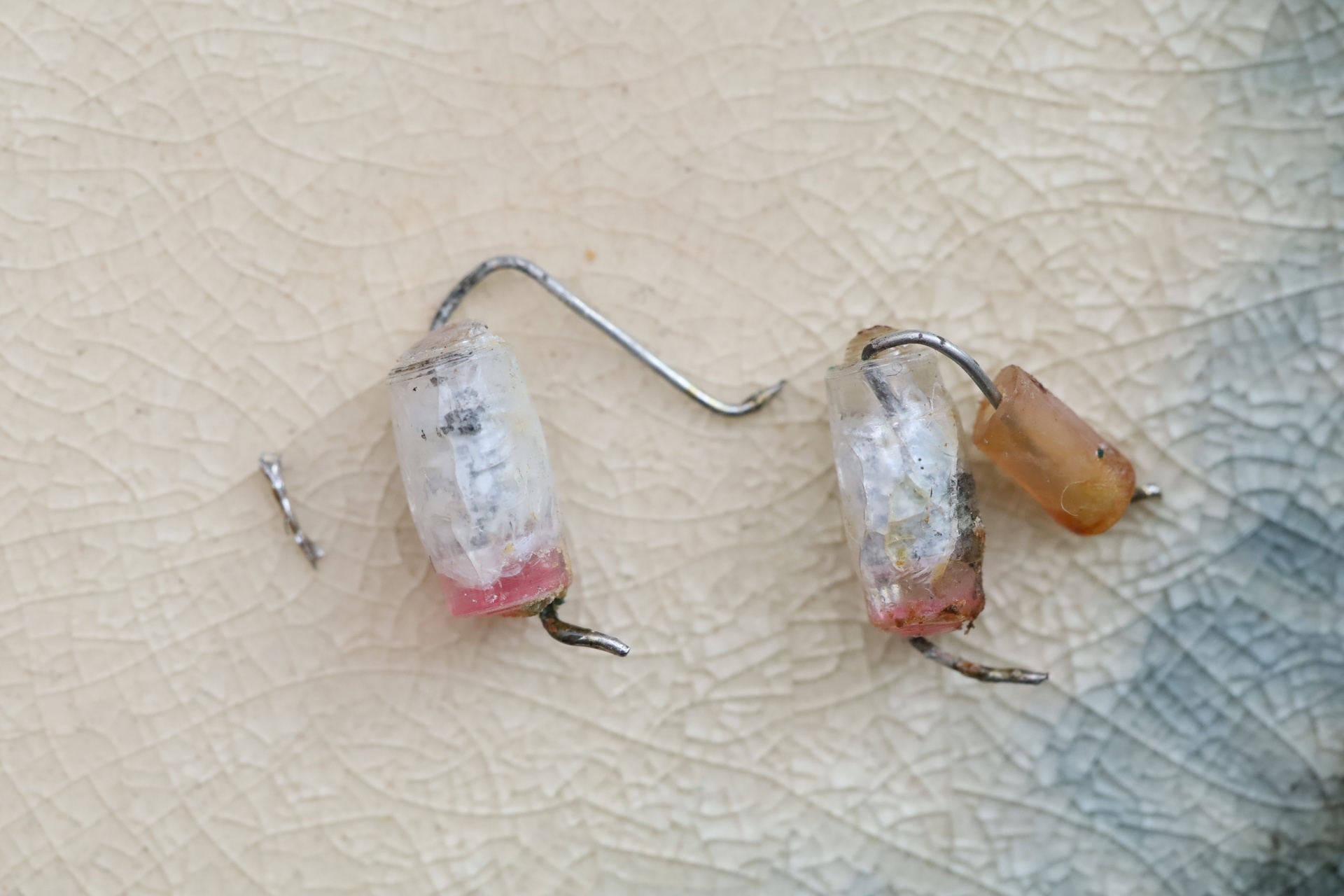
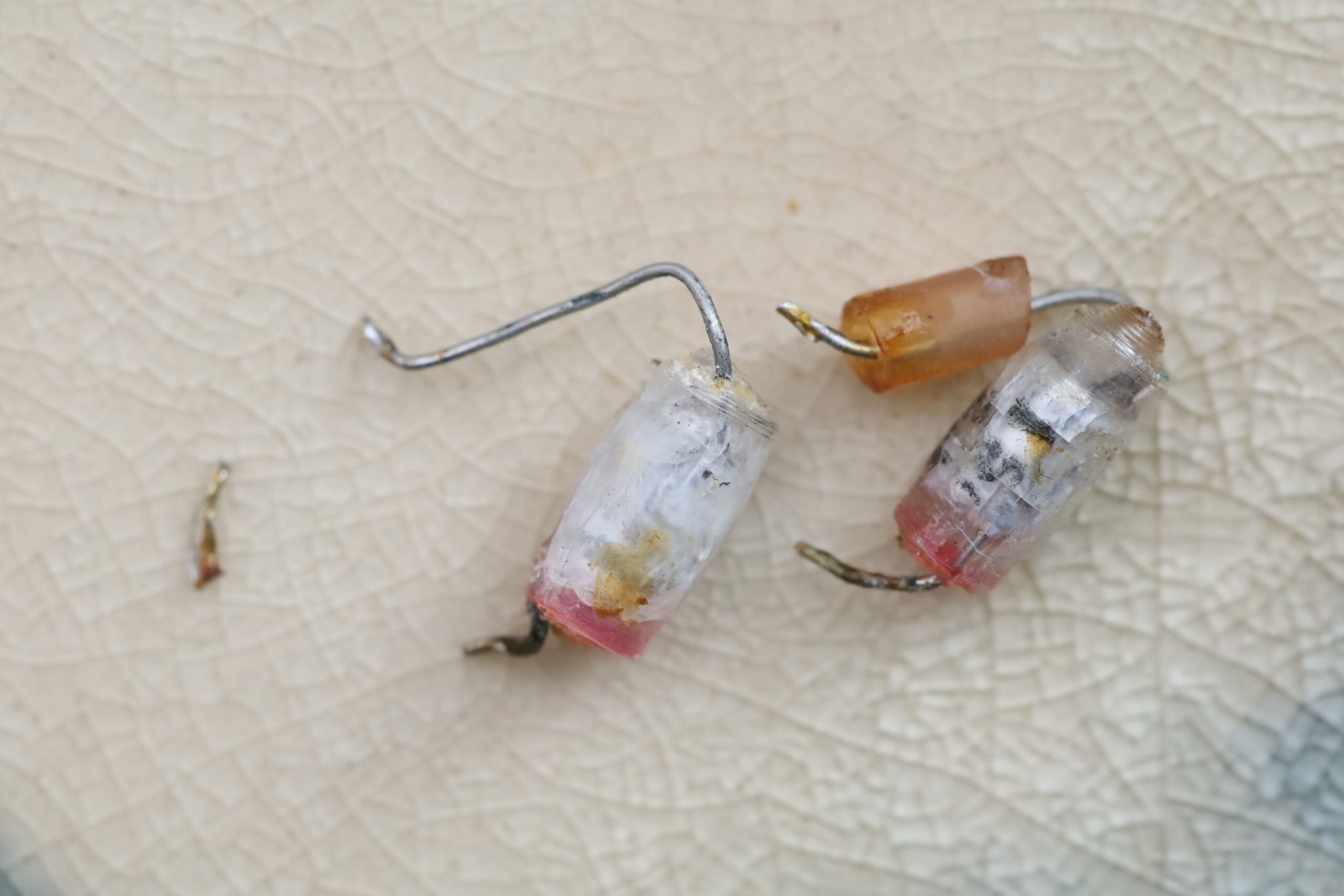
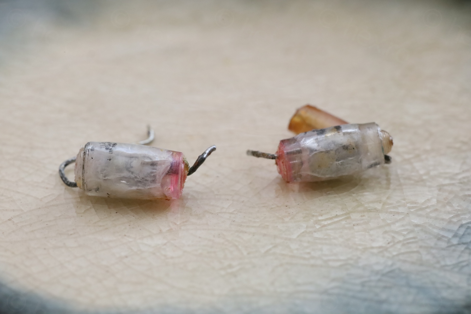
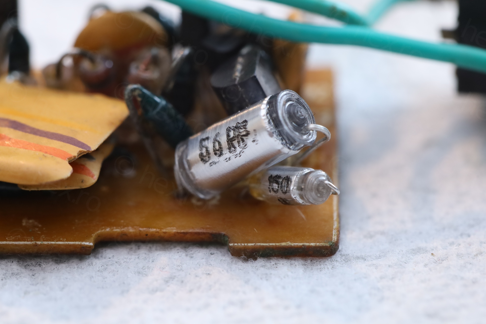
- Two polyester capacitors were cracked, corroded and with missing markings.
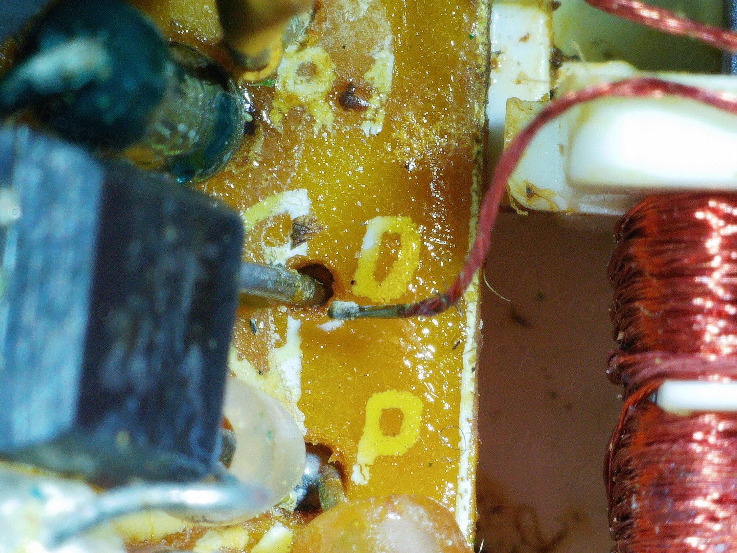
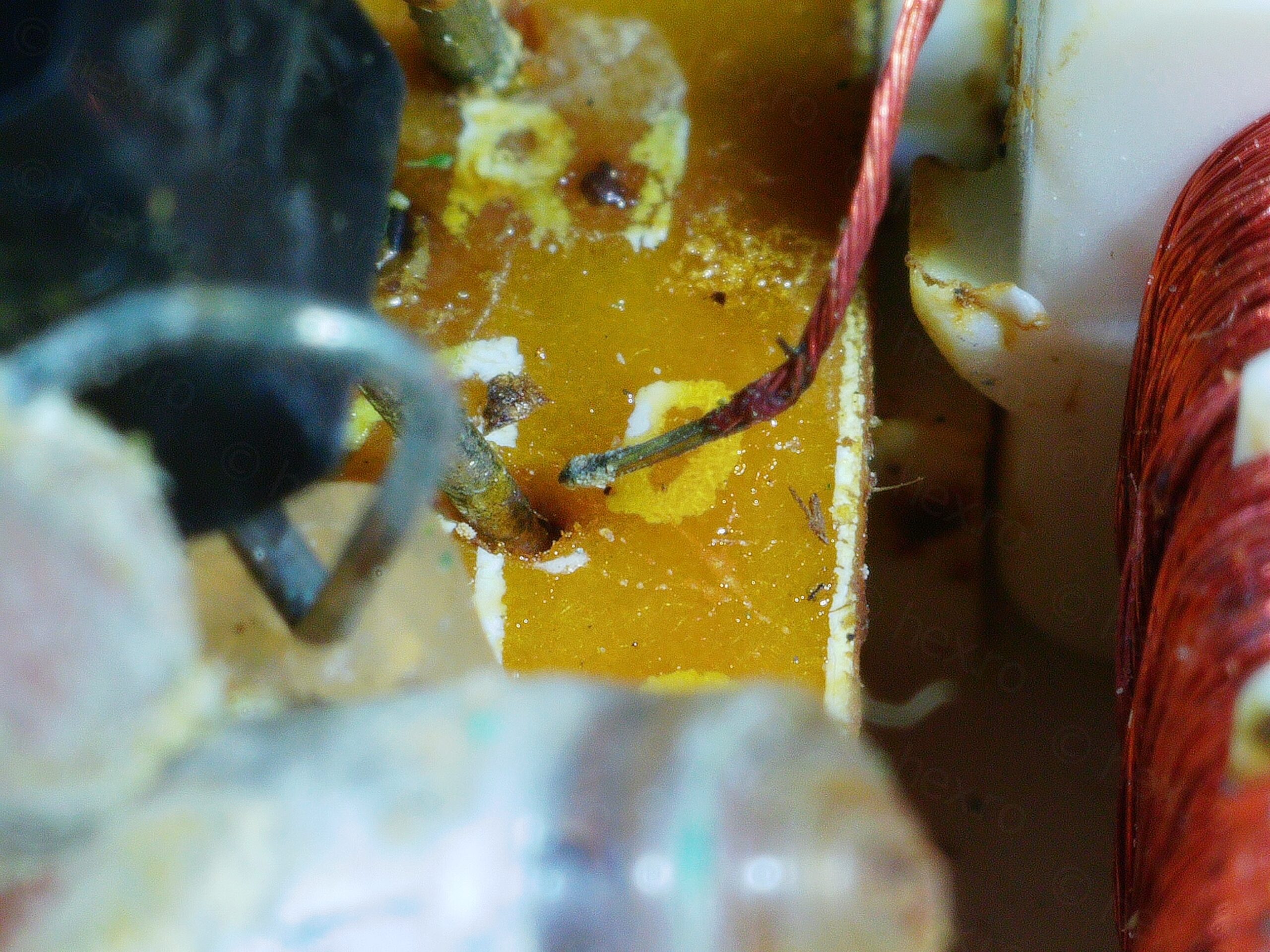
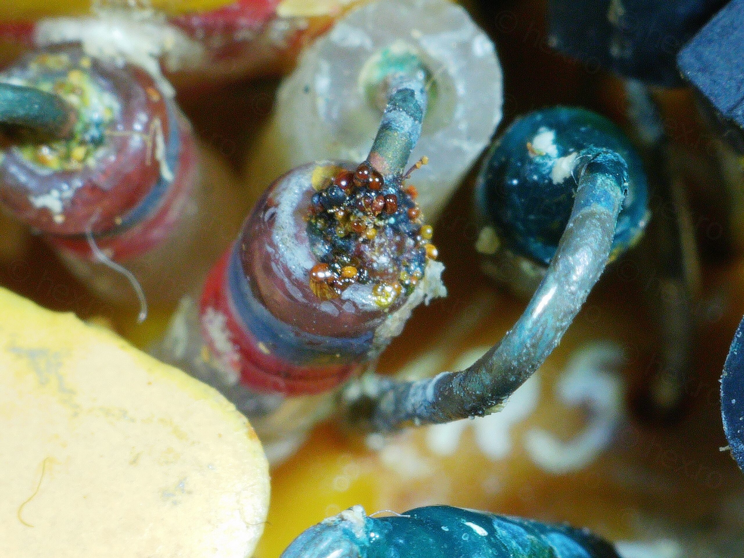
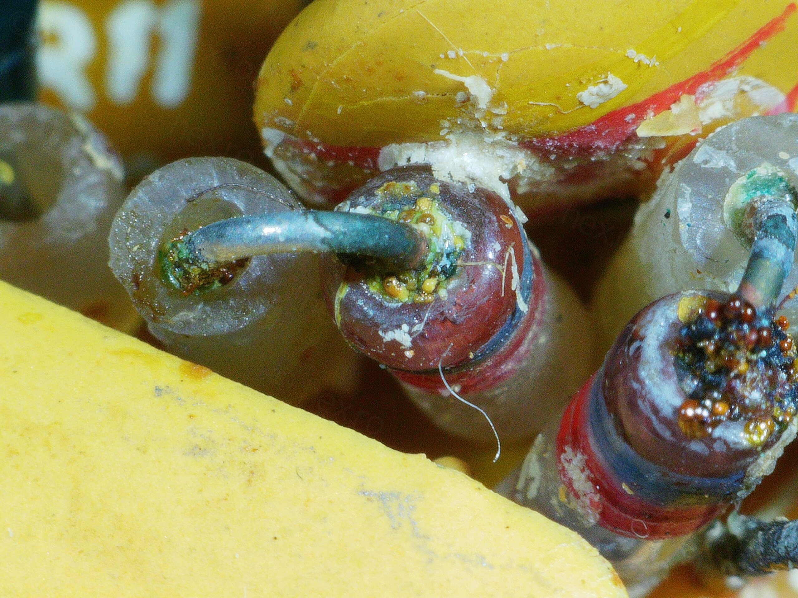
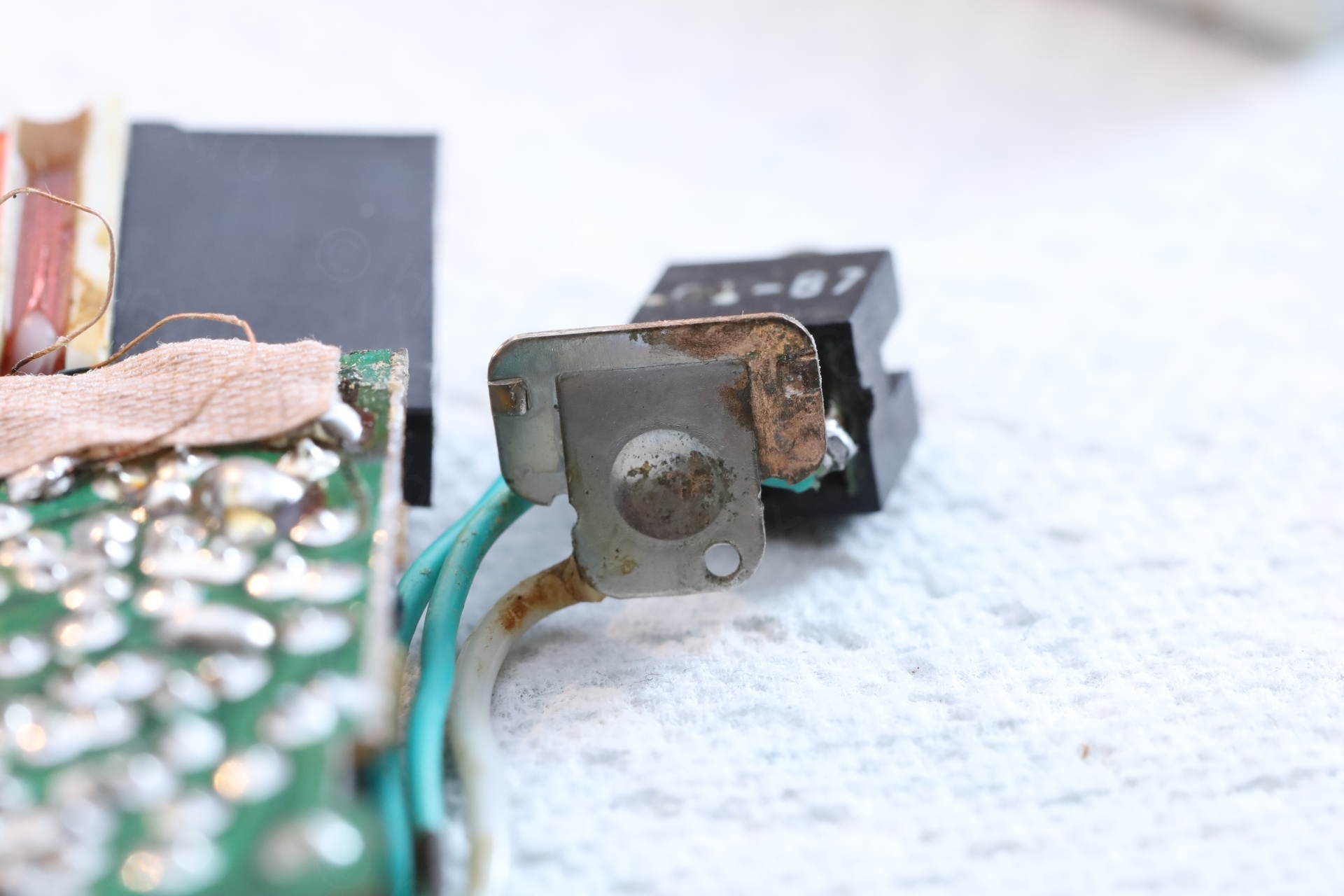
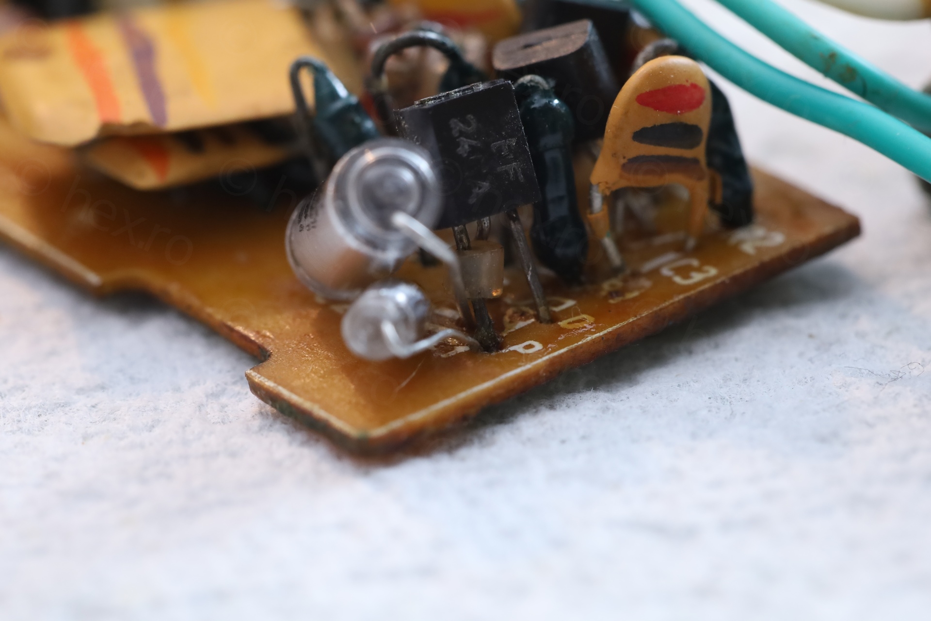
- Germanium diodes had weird brown metallic bubbly deposits where the leads were entering the glass body.
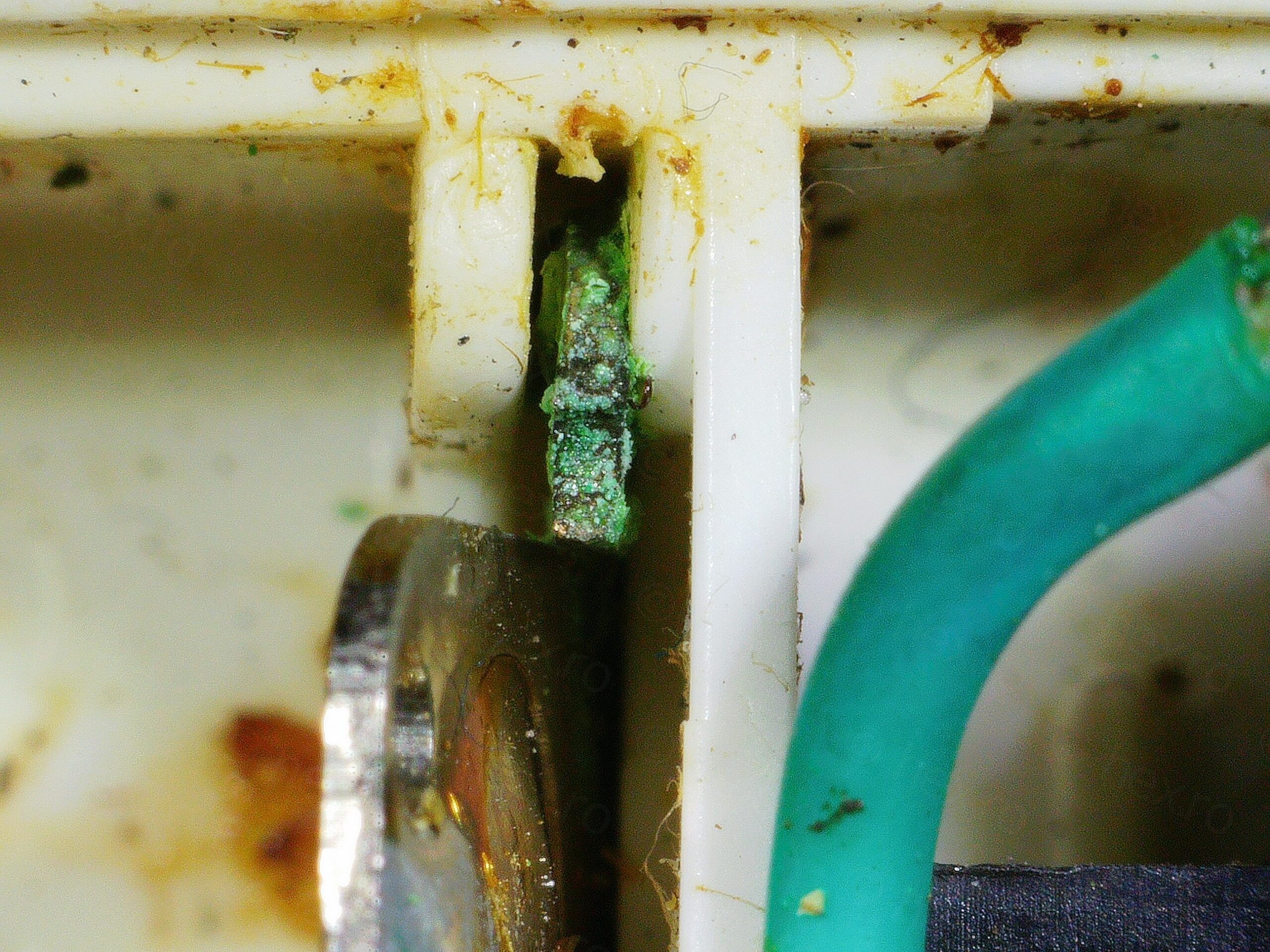
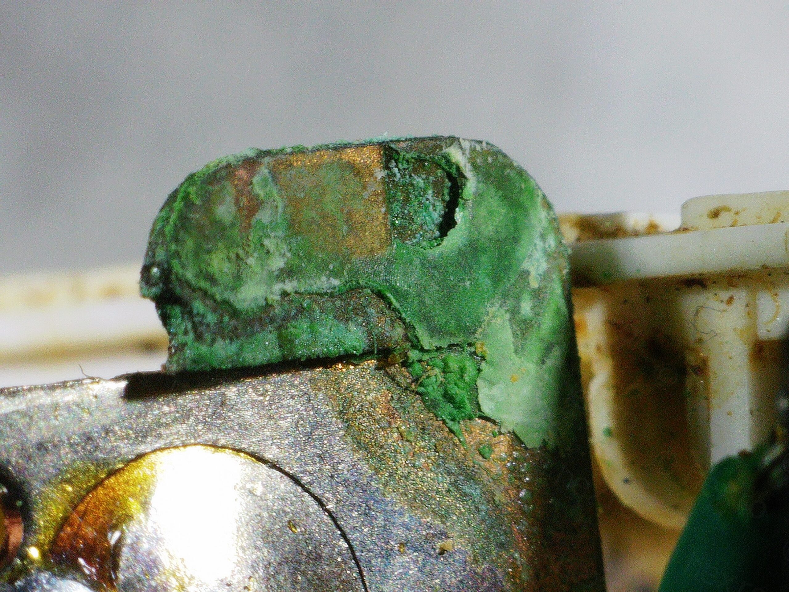
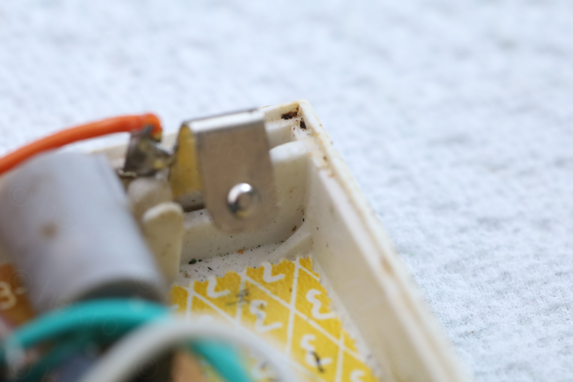
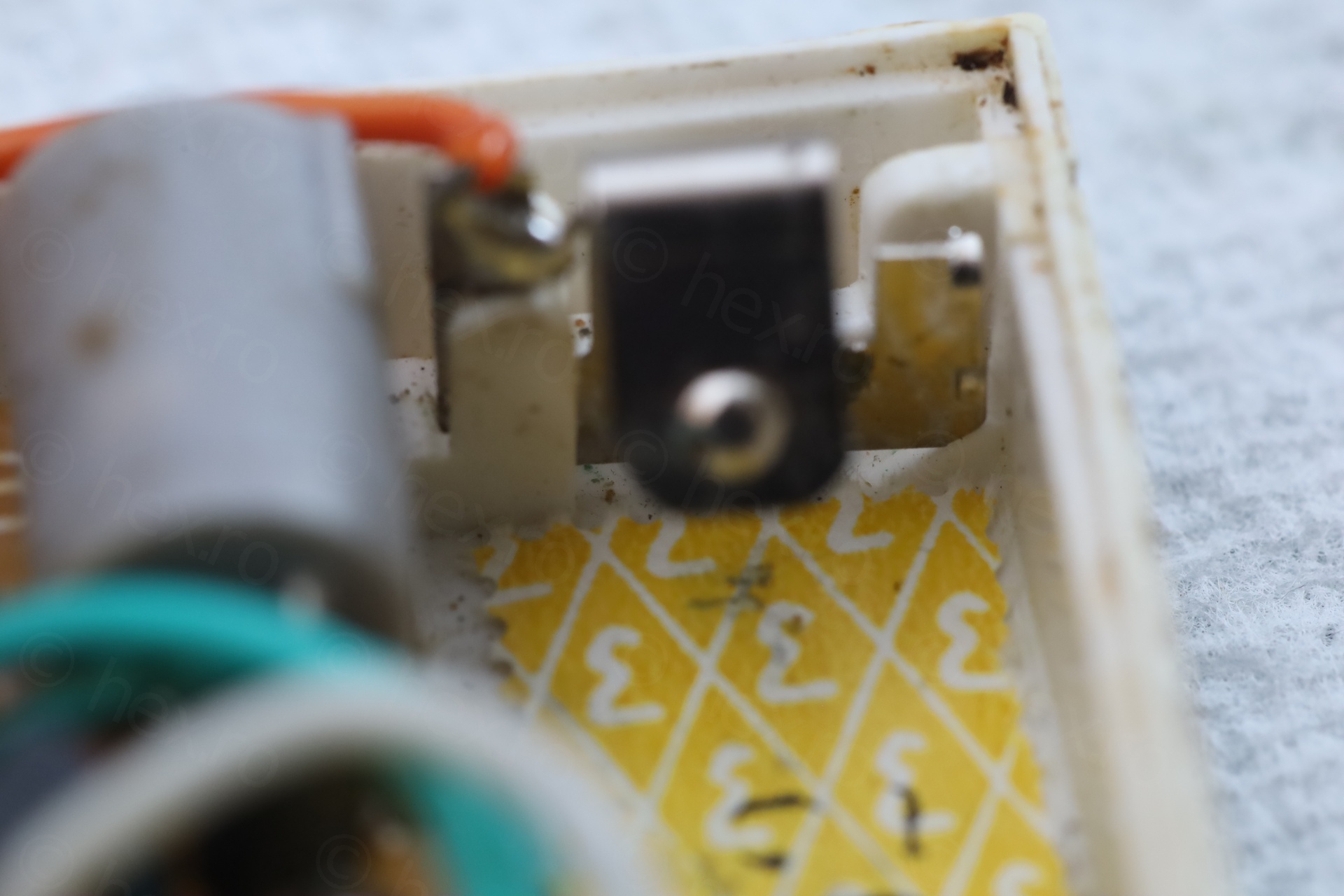
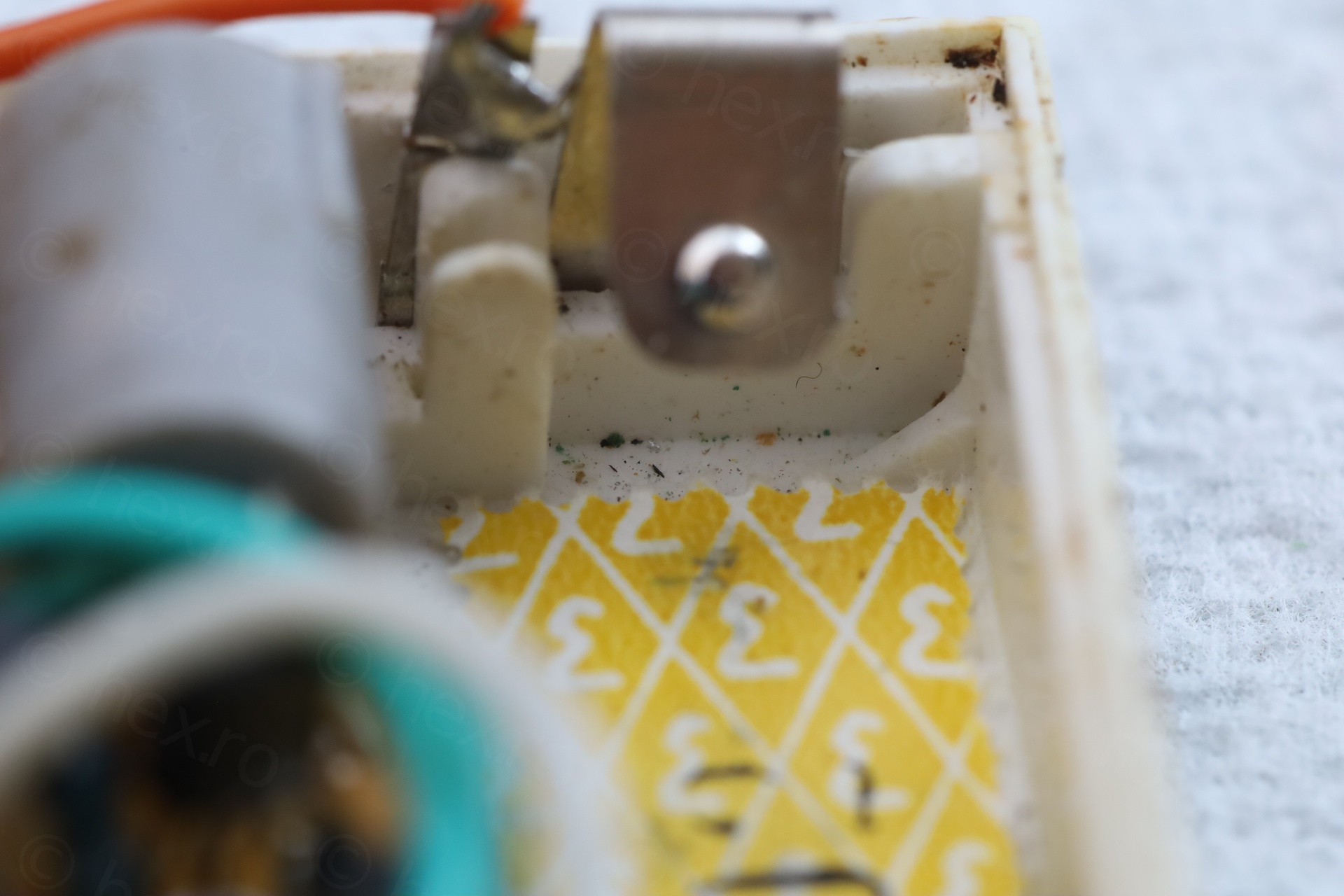
- Heavy corrosion on the blade contacts of the two buttons and on the battery
More photos below taken with microscope:
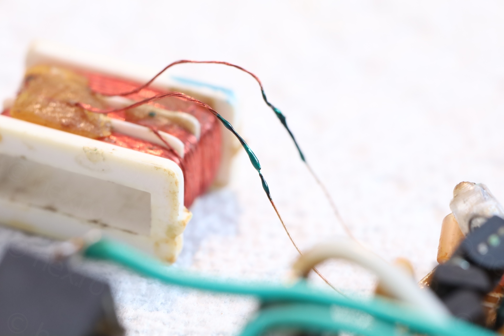
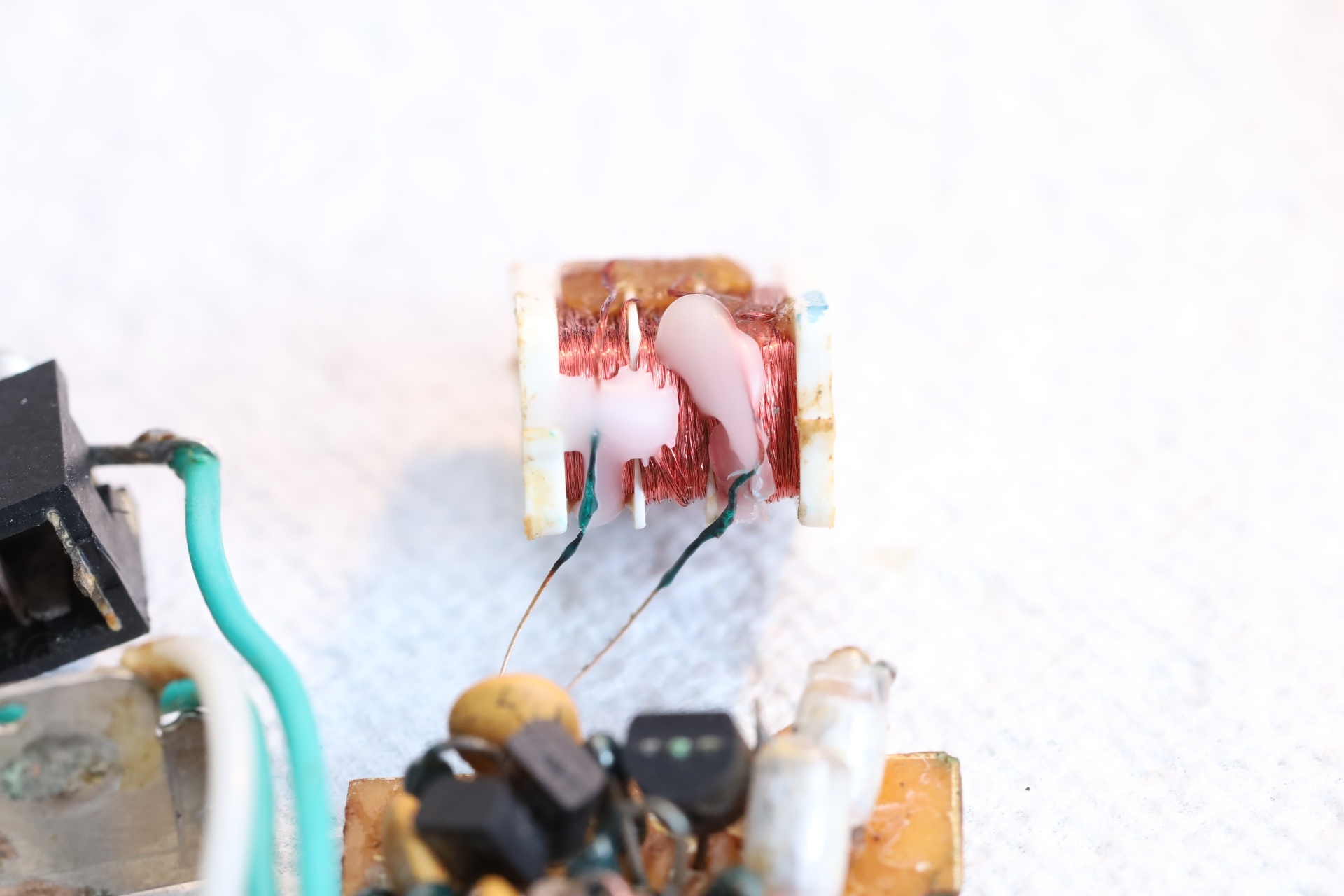
Re-enforcing the inductor
While taking photos it very quickly became obvious that I have to do something about the Litz wire that seem to break down:
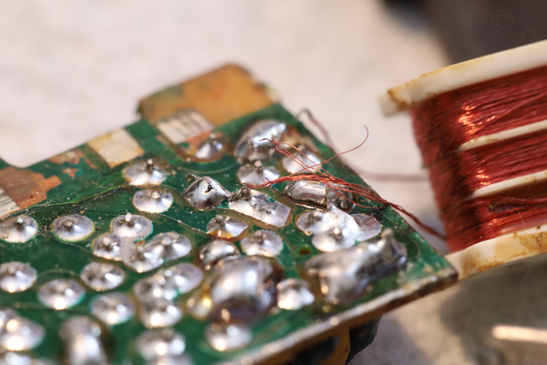
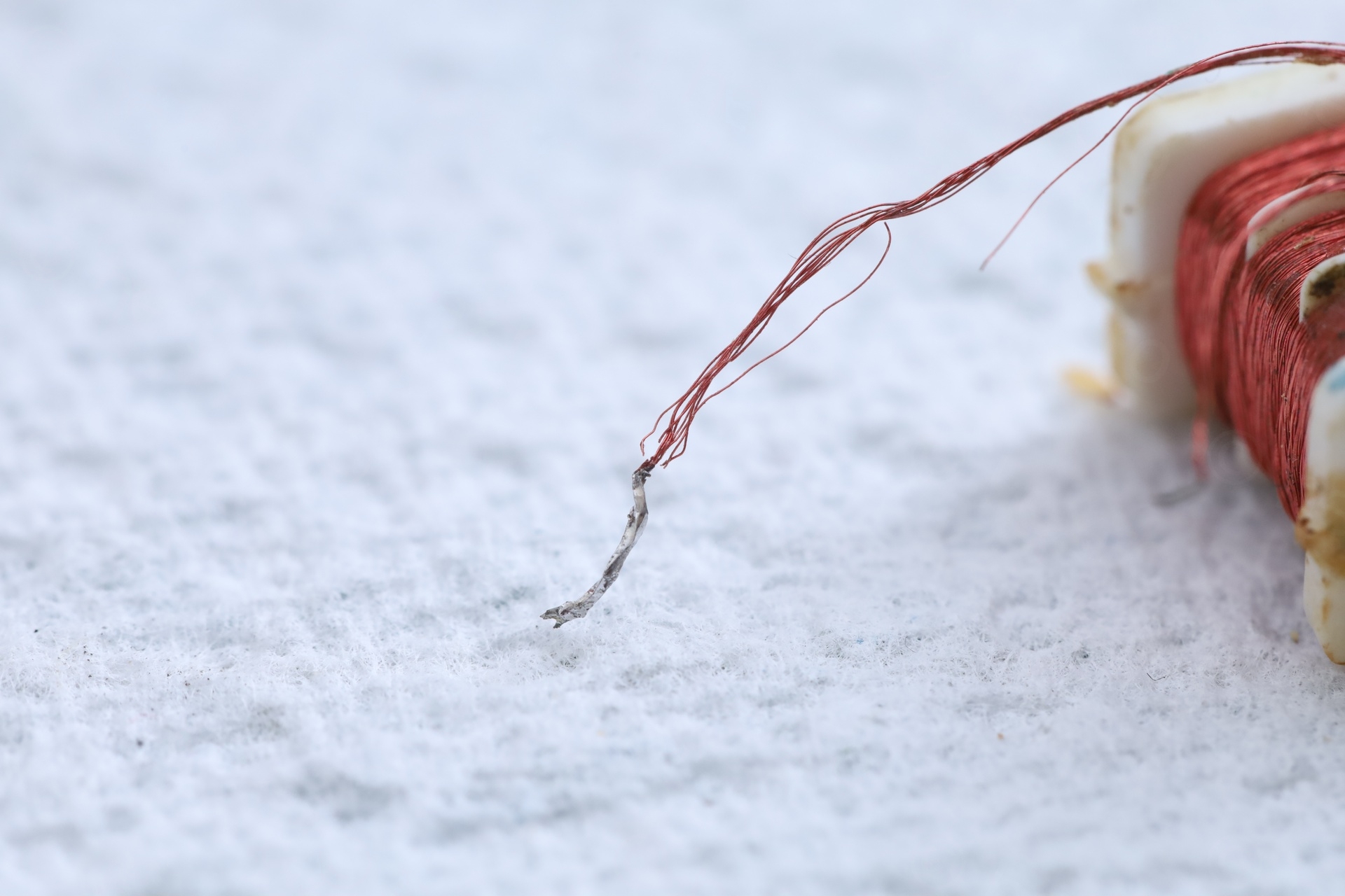
Without re-enforcing these wires, I’d soon have nothing to solder back onto the circuit board.
I devised a plan: use some enamel wire salvaged from an old inductor to make short “extensions” for the cables. I trimmed the frayed ends carefully so that each strand of the Litz wire could be soldered. Then I applied a thin coat of UV‑conformal paint, followed by a few drops of melted paraffin wax, to stop any further fraying.
Figuring out the circuit
Now that the inductor was more robust, I felt a bit more comfortable re-attaching the to the radio to do some tests. But where to attach it ? The initial disconnected end was close to one pin of a transistor, but was it really where it should have been ? Using Gimp, and a lot of back and forth between schematics and the board, I managed to shine some light into the crowded space:
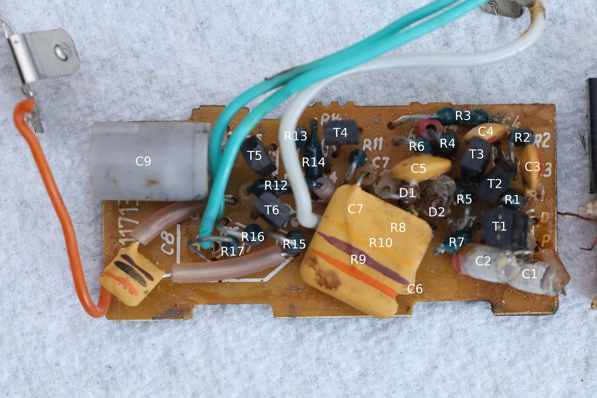
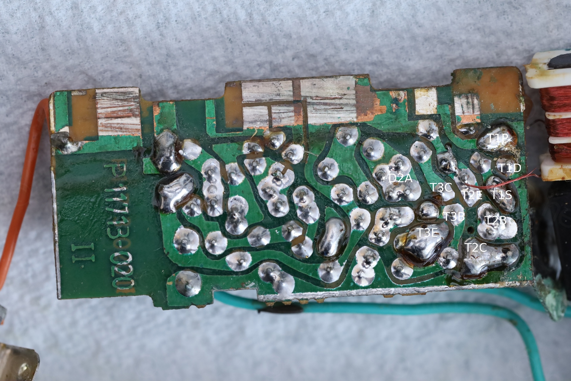
Now it was obvious where to hook the inductor.
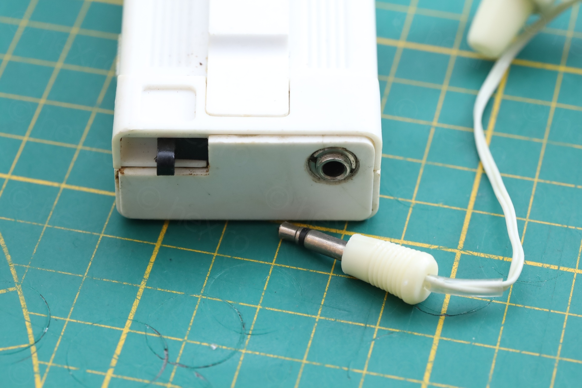
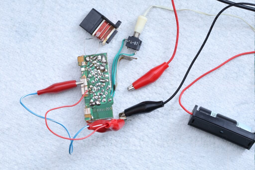
First power on!
The radio Volume button connects the battery ground to the rest of the circuit. I had to use some crocodile leads to bring the ground where it should. This way circuit board could still be probed, without having to have it inside the radio:
Results were not good. Radio was hissing alright, but wasn’t receiving anything. TinySA signal wasn’t picked up. Out of frustration, I started scanning, and … to my surprise, radio was completely ‘de-tuned’, receiving between 1.73MHz and 3.69MHz:
The positive thing is that at least the audio amplifier part of the radio works fine. The AM decoding is also fine, Germanium diodes weren’t affected by the corrosion. But still, where is the problem ?
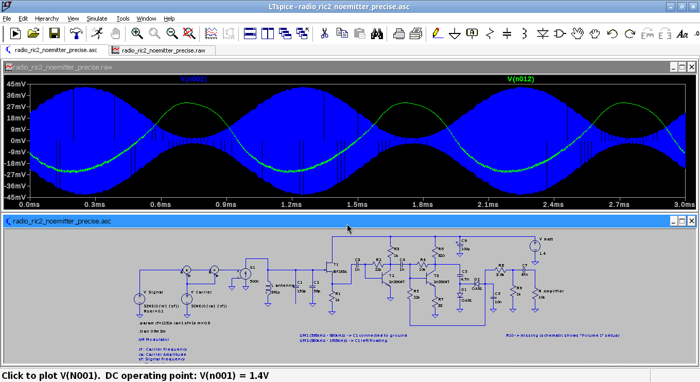
My first reflex was to simulate the RF front-end into LTspice and then cross check the radio with the simulated values:
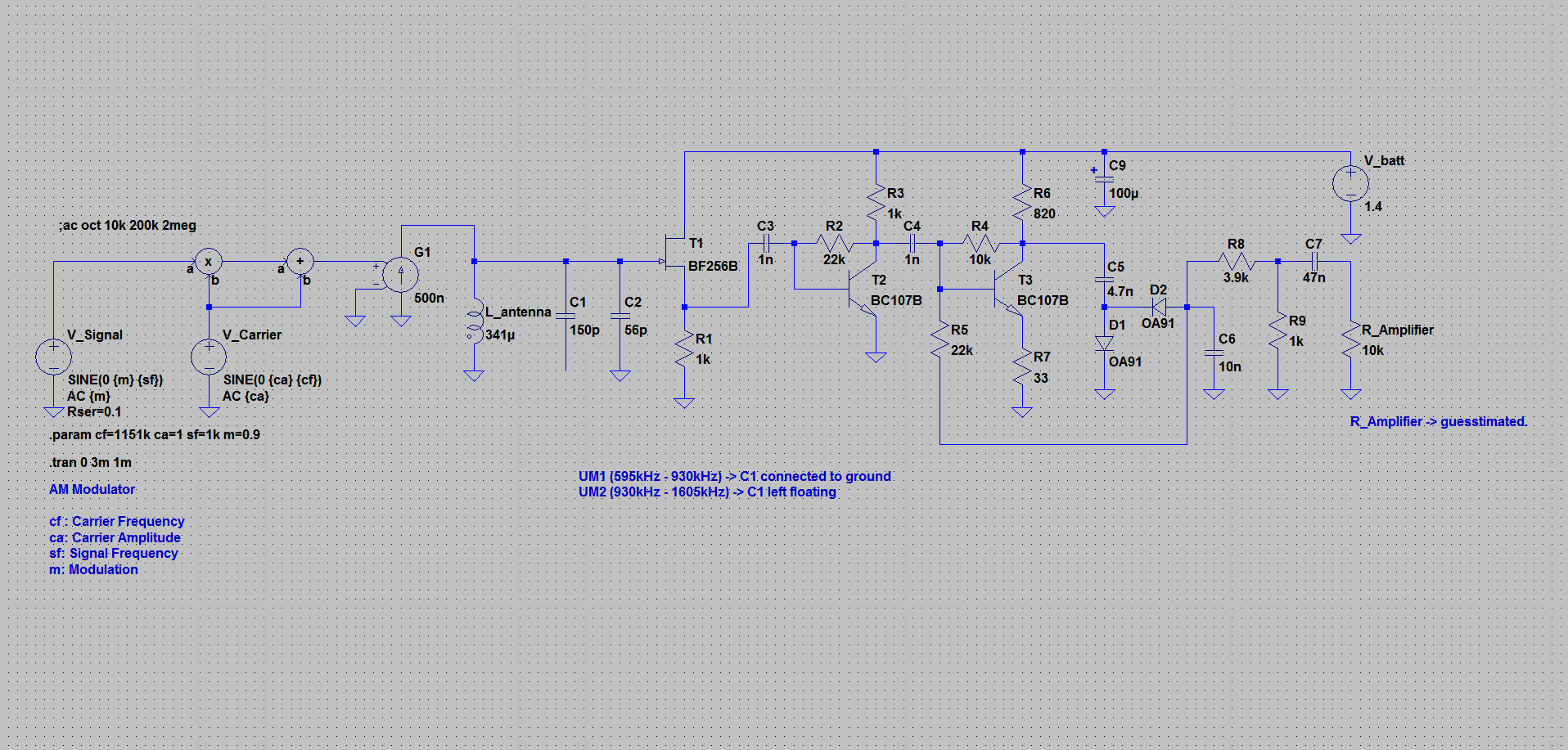
Simulation works fine (I chose 1151kHz frequency, to be in the UM2 range, just with C2 connected). Voltages seemed close to the schematic indicated ones. At least now I had a reference to cross-check against, without a second working radio.
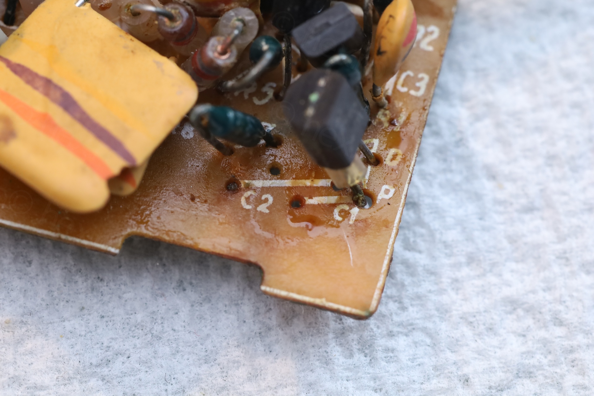
With the circuit board out, the C1 is not connected to ground -> and I was able to measure it at exactly 150pF. C2 is always in circuit so I cannot measure it.
Antenna measurements
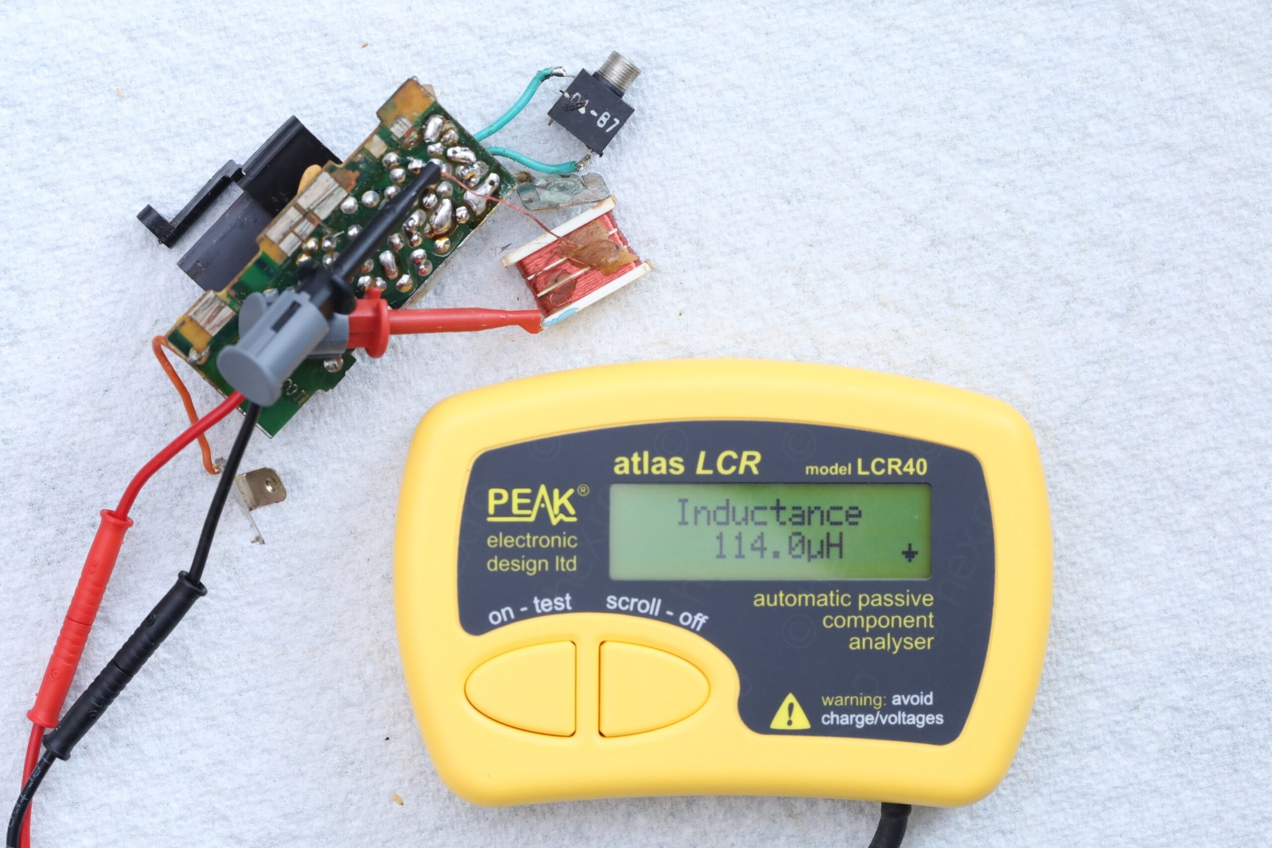
Before starting to work on the inductor, I did take some measurements, just to be sure, in case something goes wrong, that I could replicate it.
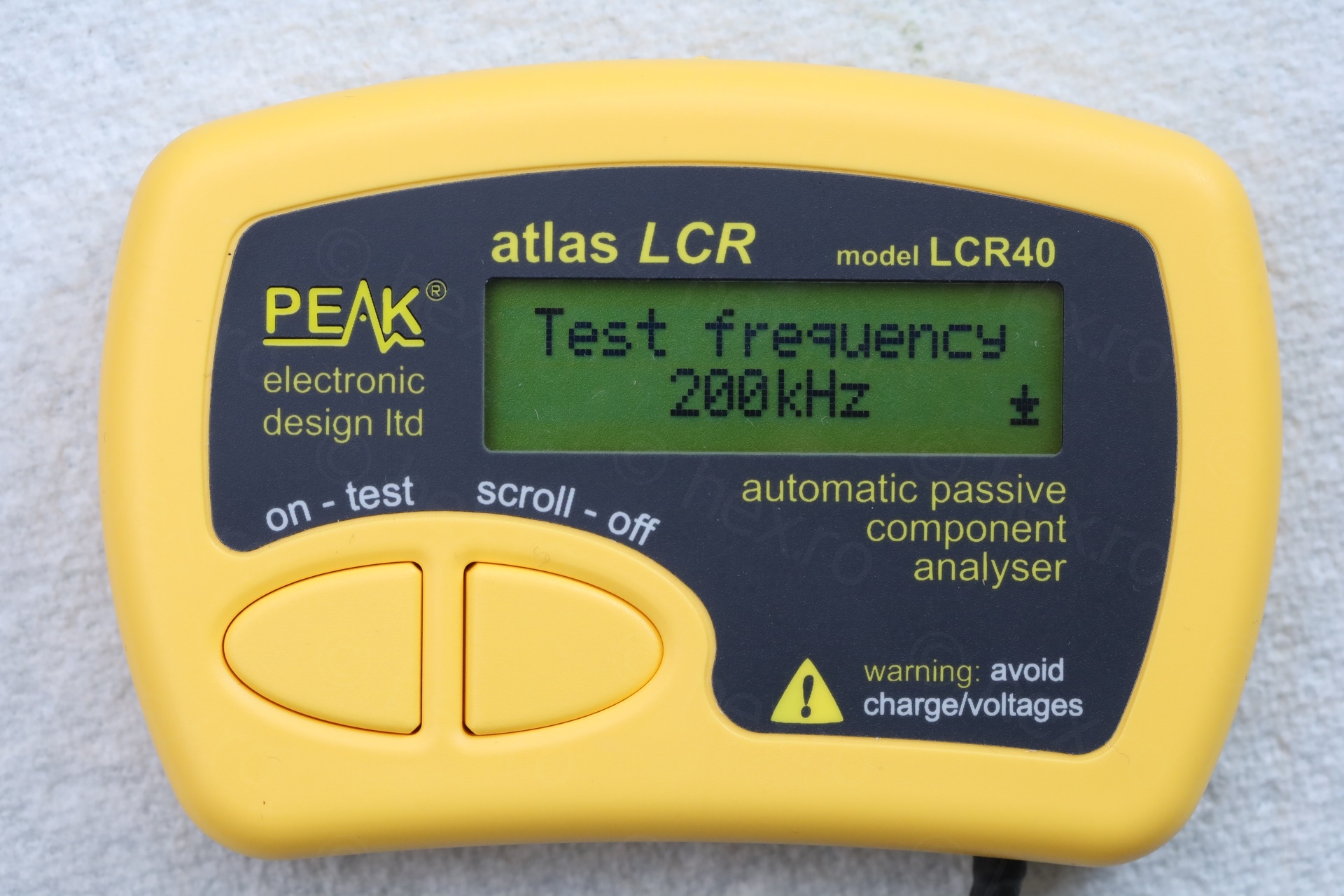
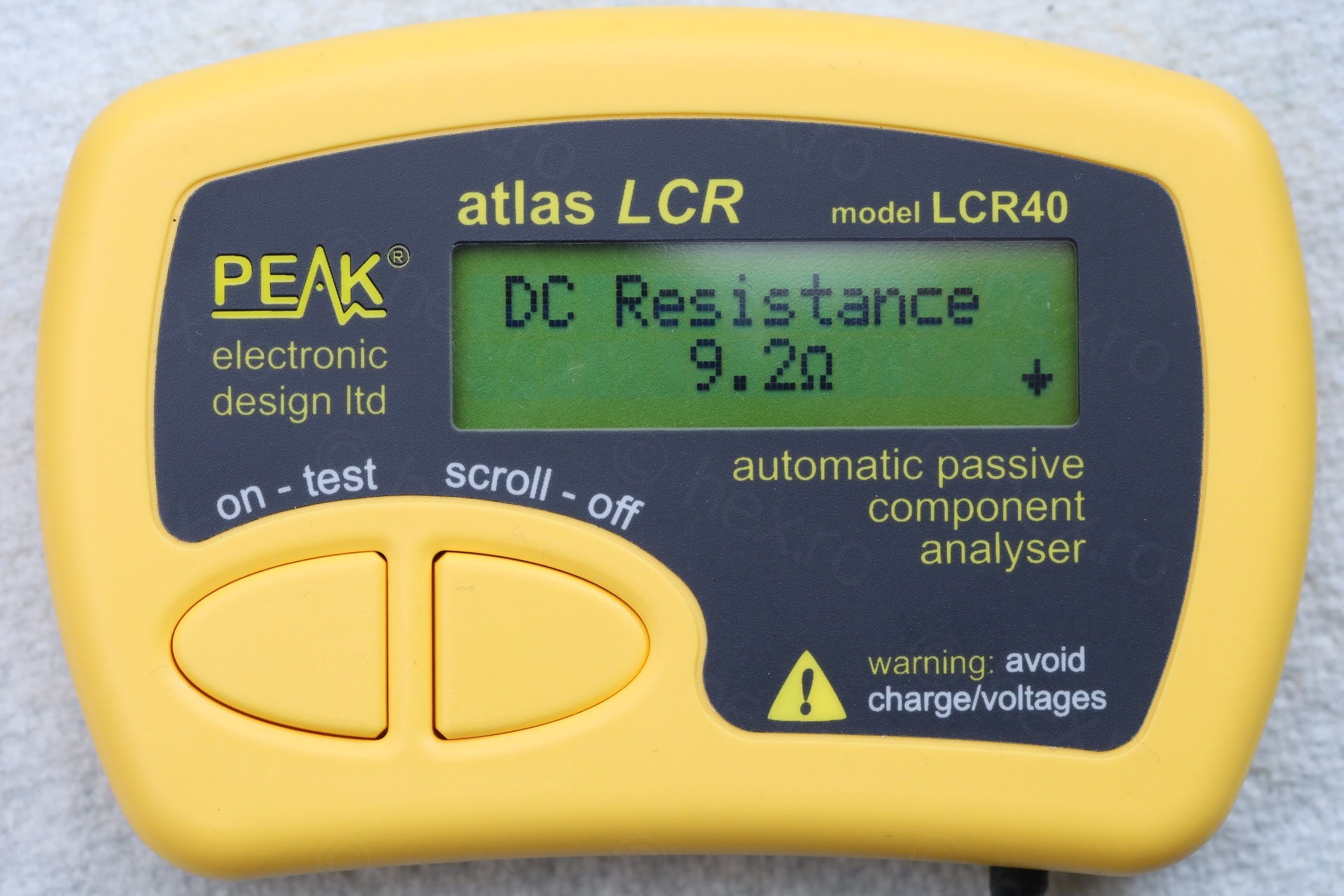
The Peak Atlas LCR was reporting 114uH (at 200kHz) and a DC resistance of 9.2 ohms.
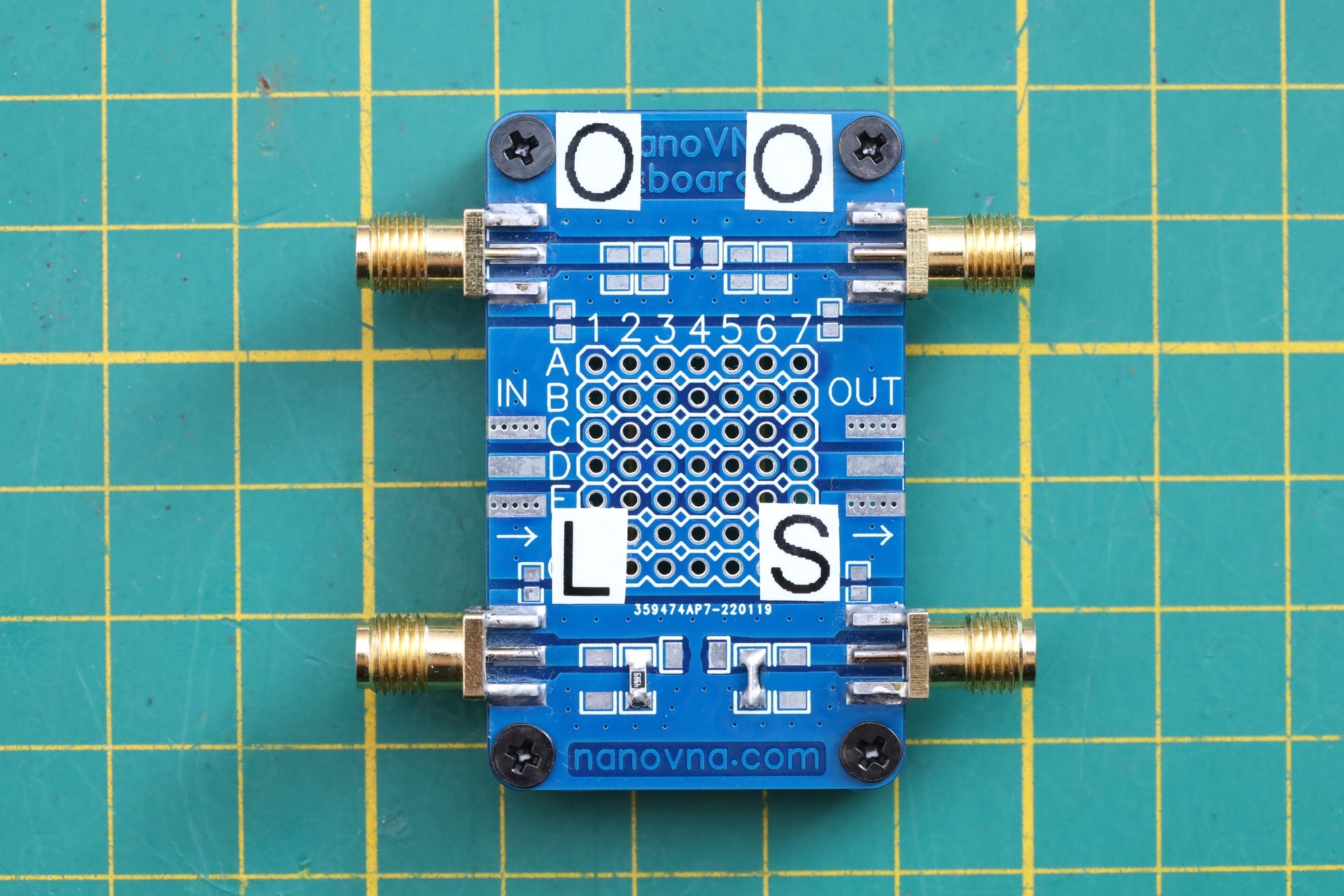
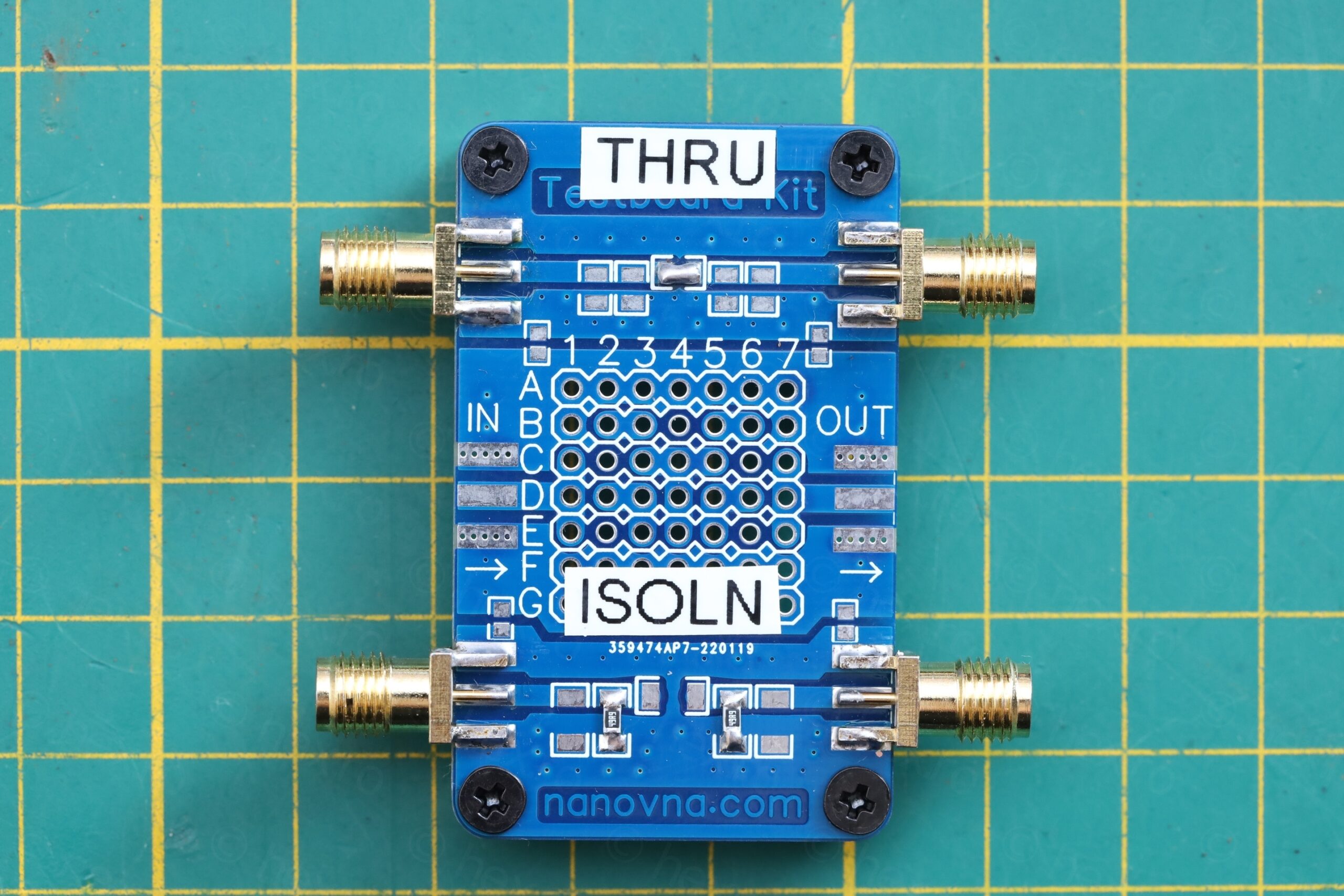
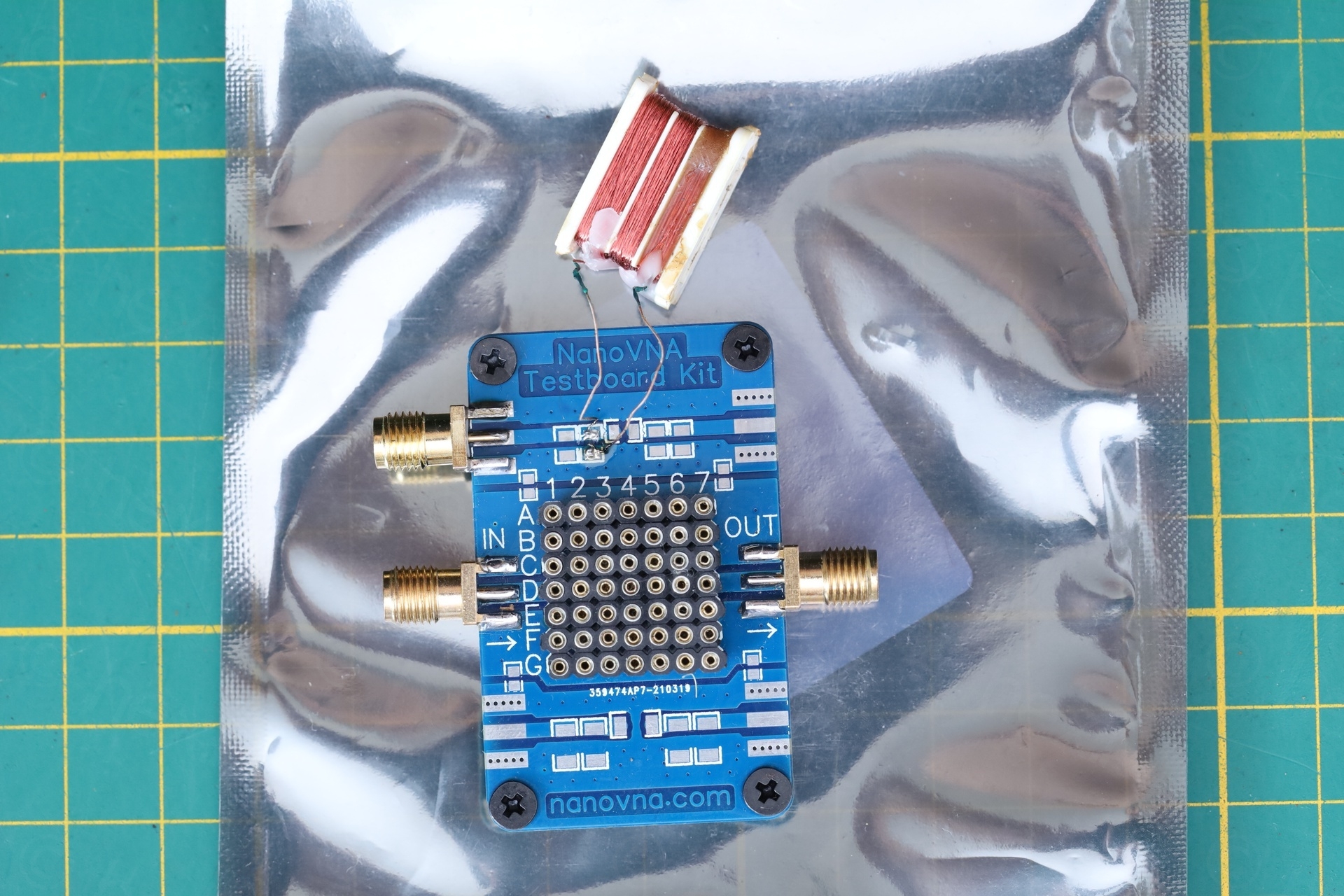
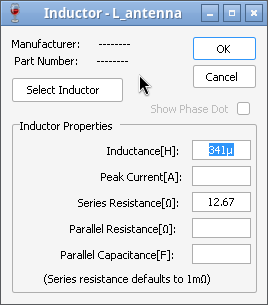
But once I had the inductor fixed, I could now characterize it using the NanoVNA, as I wasn’t afraid to solder it anymore. There are these kit boards to measure parts, made for NanoVNA and one would hope the boards all have the same RF characteristics. I chose the pads where I’d solder the inductor, proceeded to create two SLOT standards, then soldered the antenna onto the respective pads on the third board. Now I was able to calibrate the NanoVNA:
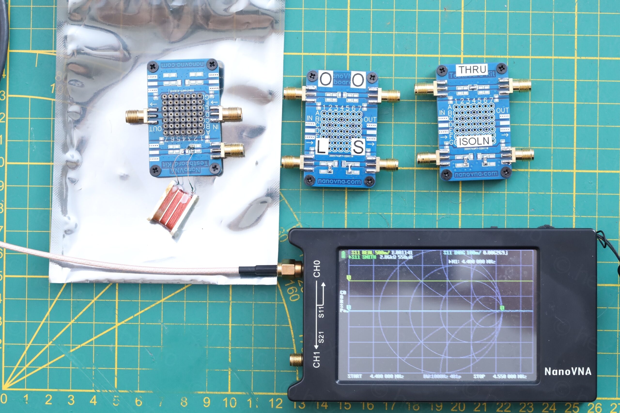
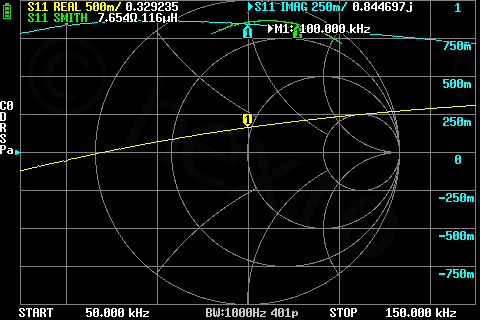
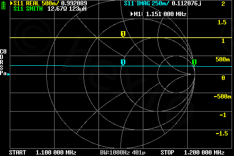
First results, Peak Atlas LCR40 is good, at 100kHz (left), NanoVNA reports 7.65Ω and 116µH. At 1151kHz (the random chosen frequency), the antenna measures 123µH and12.6Ω:
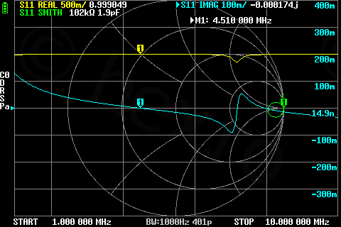
Out of curiosity, I did a wider scan, just to see the antenna self-resonant frequency, and it turns out to be at 4.5 MHz:
All the tests were done without the ferrite rod inserted.
With the ferrite rod, I didn’t take screenshots, but previous measurements shown it to be 520µH.
As I was playing more and more with the simulation, reading about other Tuned Radio Frequency radios, etc, I became more and more convinced the problem has to be in the RF section. Especially with C2 that is always connected. But is it the capacitor or the JFET ?
C2 Capacitor
Based on the tests with the Tiny SA, I saw that:
- With ferrite rod fully inserted (L=520µH) , the signal is received at 1.73Mhz.
- With ferrite rod fully separated (L=114µH), the signal is received at 3.69Mhz
Formula to calculate the capacitor in an parallel LC tank circuit, knowing frequency and the inductance is:
$$C = \frac{1}{(2\pi f)^2 L}$$
Plugging in the values:
- 114uH at 3.69Mhz => C2 = 16.27pF
- 520uH at 1.73Mhz => C2 = 16.31pF
This was the Eureka moment. C2, instead of measuring 56pF, acts like it measures 16pF. Ahaaam. It must be the C2!
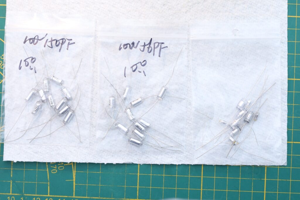
Since I wanted to preserve the look of the radio, I did order polystyrene capacitors – even if I could have used more modern ones.
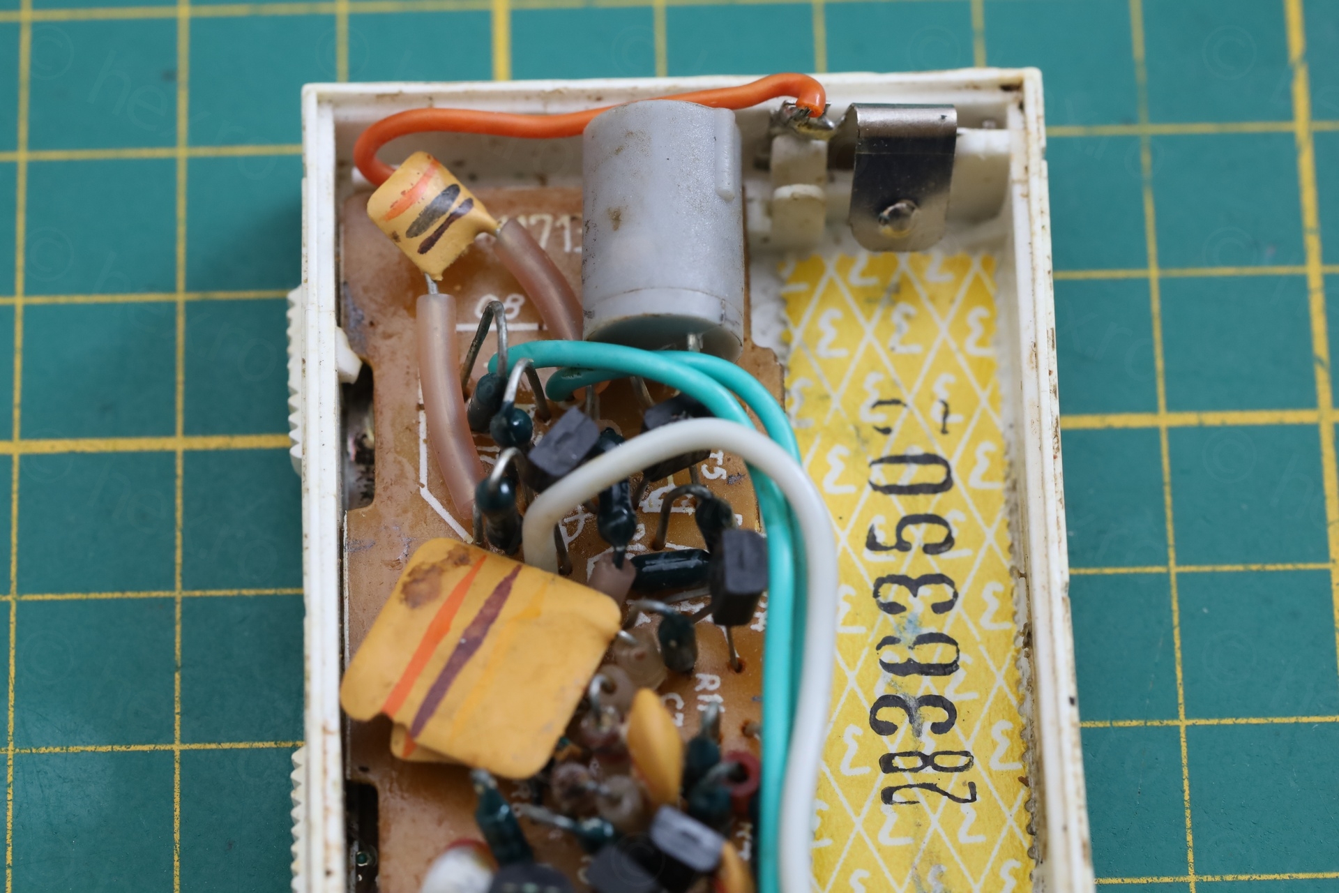
Corrosion cleanup
While waiting for the new capacitors to arrive, I figured I should take care of the corrosion. This boiled down to use a grinding pen with a very fine tip and going around the green deposits, never dwelling too much on one spot, and cleaning with a brush as well as with IPA:

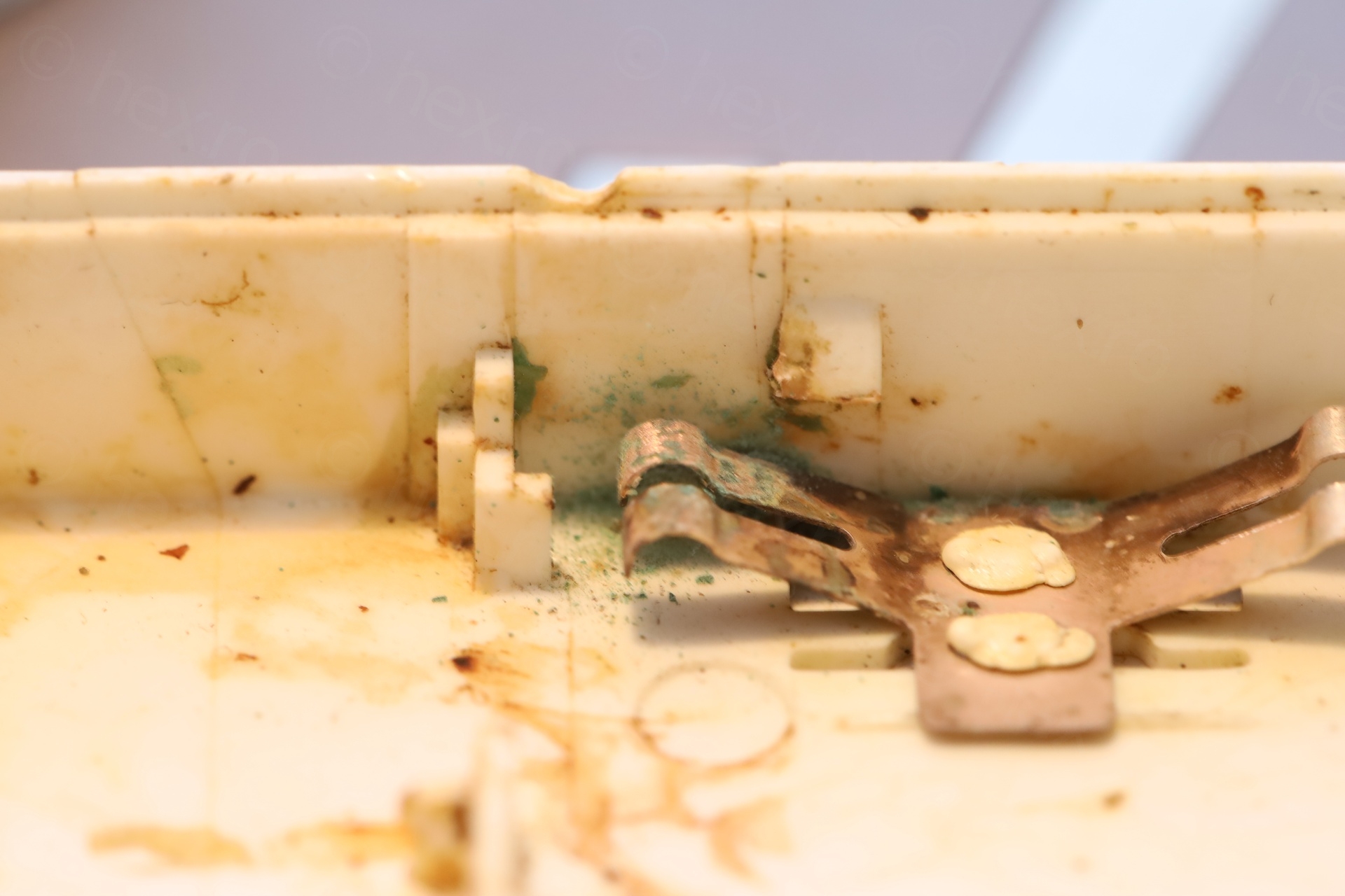
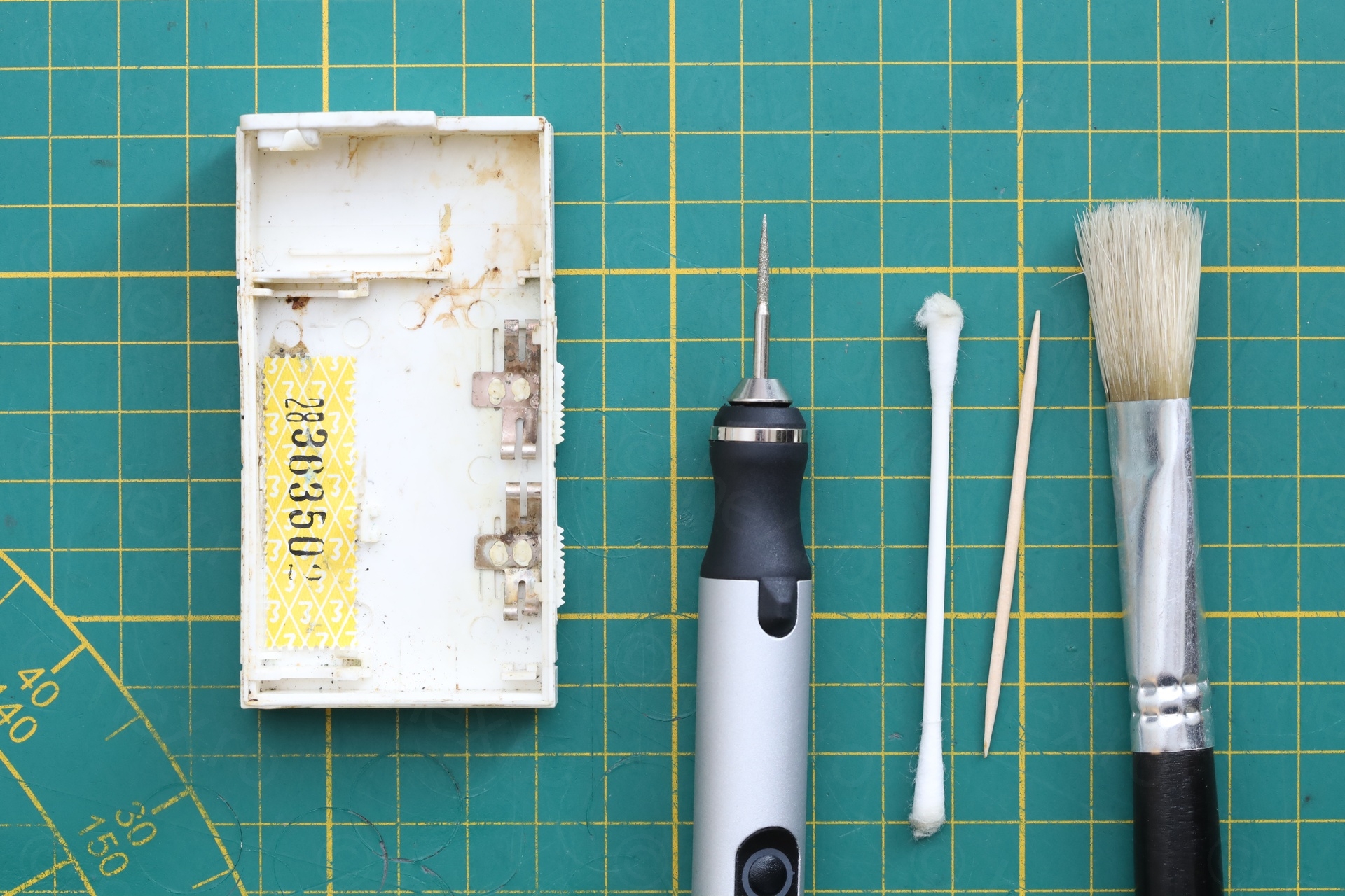
Thankfully there was plenty of material. The metal blade contacts of the two sliding switches were fragile, since they are attached with plastic that is melted. One of the blades (lower right is bent weirdly, but I left it as is, it still makes contact), out of the same fear – a bit more pressure and they’d snap.
The same treatment was applied to the diodes and the JFET which had corrosion on its middle pin on top. Photos after, below:
Replacing C2
I placed two orders from two different places and while they did arrive, to my surprise, the new 56pF (from both orders) were huge (I assume, rated for much higher voltage than the originals):
The decision was to replace both capacitors, as they share a pad and there was a risk that the heat of de-soldering C2 may affect C1 (since they are polystyrene).
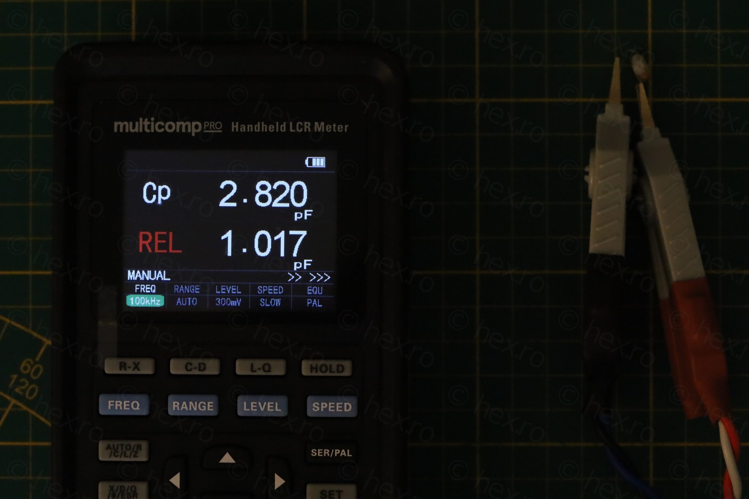
And indeed, C2 was faulty and measuring 3pF (at 100kHz):
The C1 survived the de-soldering.
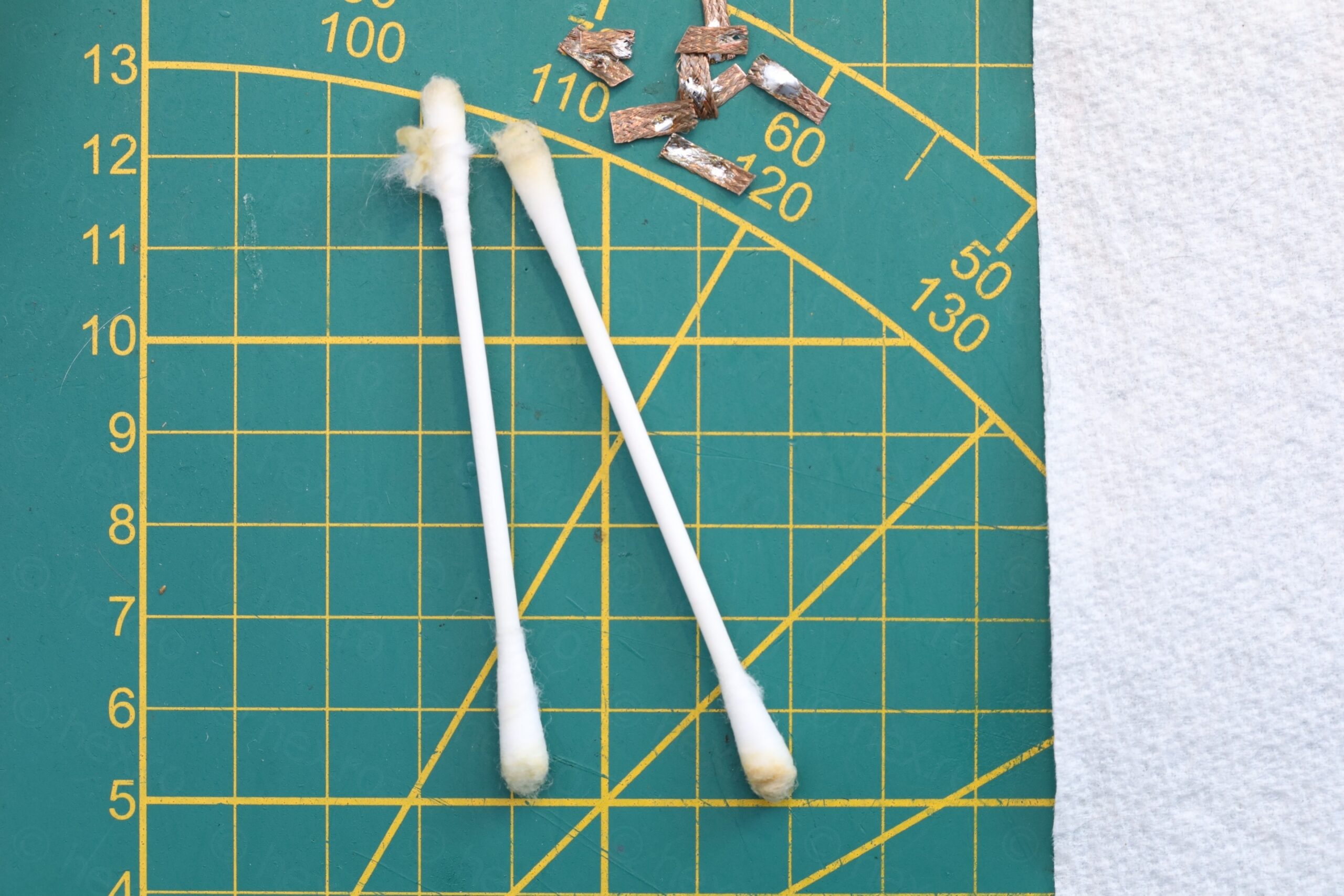
I selected two capacitors from the new ones and proceeded to install them. Since I was keen in preserving the circuit board, I didn’t use the high temperature vacuum de-soldering pump, but struggled with low-temp and solder wick plus lots of flux:
The 56pF required to be soldered a bit higher above the circuit board so that it can be folded, to allow for back case of the radio to fit properly.
Results are good – radio was now re-tuned and the new ranges found with TinySA are:
UM1: 486khz -> 826kHz
UM2: 866kHz -> 1485kHz
Both ranges are shifted ~100kHz down (compared to specs) but I’ll leave it as is. One thing to note, inside the radio, the ferrite rod does sit a bit inserted into the antenna.
I forgot to mention that the radio has to be switched between UM1 / UM2 to cover the whole AM band – since it can’t cover the entire range with the tiny inductor / ferrite. When the Band Switch is in UM2 position (C1 is left floating, only C2 stays in parallel with the antenna) radio is meant to receive on 930kHz -1605kHz. When switch is moved to UM1 position, the switch blades connect C1 to GND. Thus, the capacitance of the tank circuit increases from 56pF to 56pF + 150pF, and now radio will receive in 595kHz – 930kHz.
Here in Brussels, I was able to listen to TalkSport from UK, they were transmitting Leeds vs West Ham. The volume was low (understandable), but improves a lot using a Tecsun AN-200 tunable loop antenna.
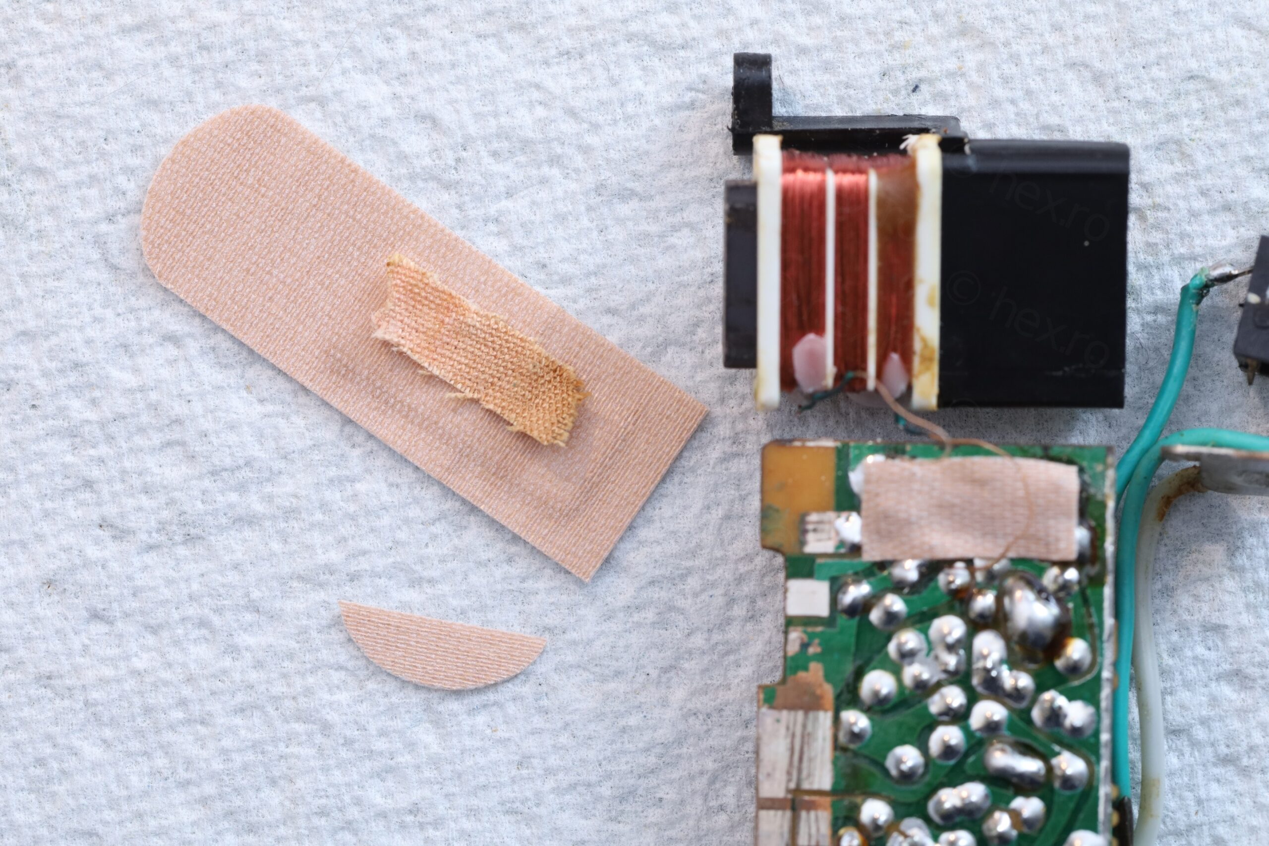
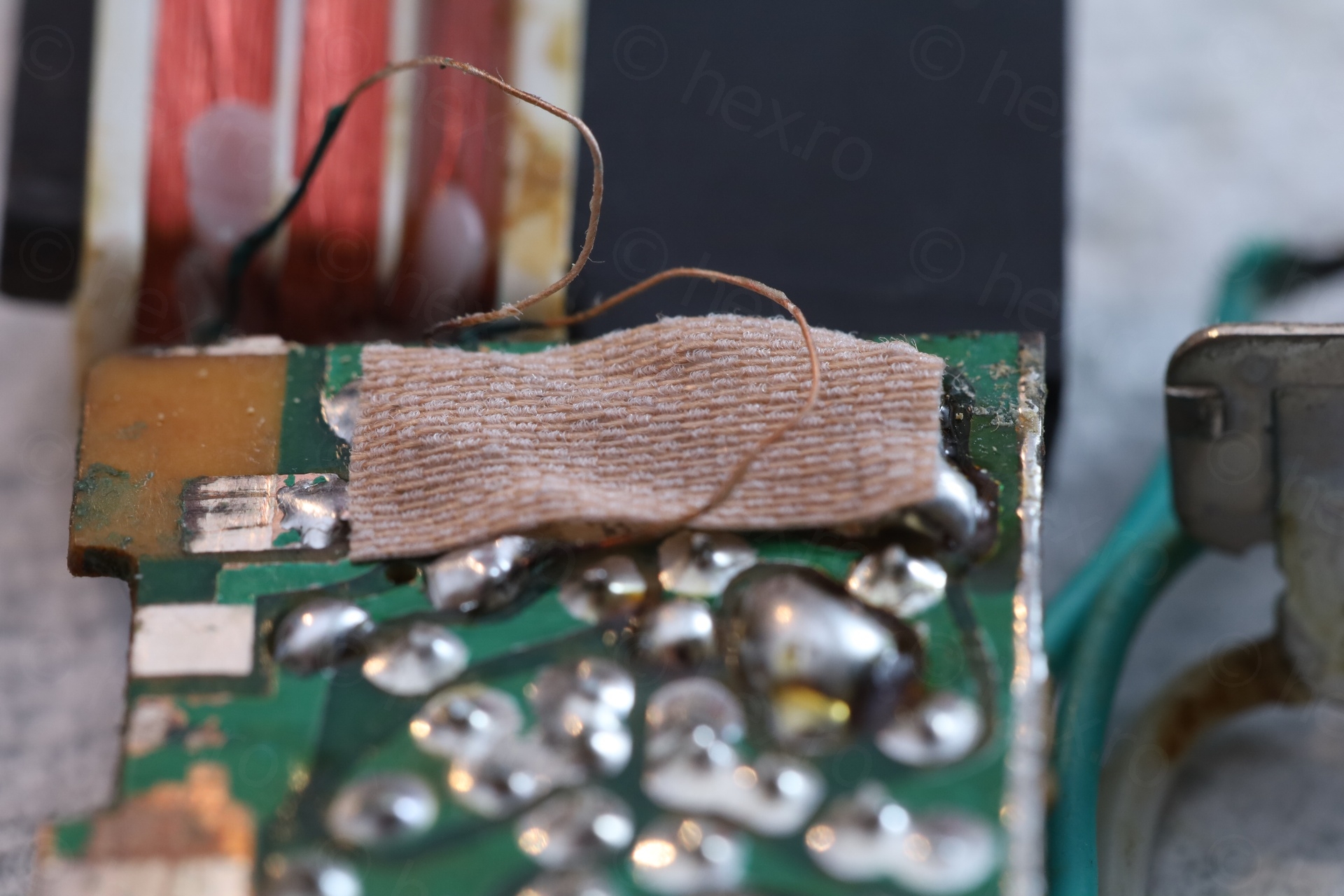
Putting it back together
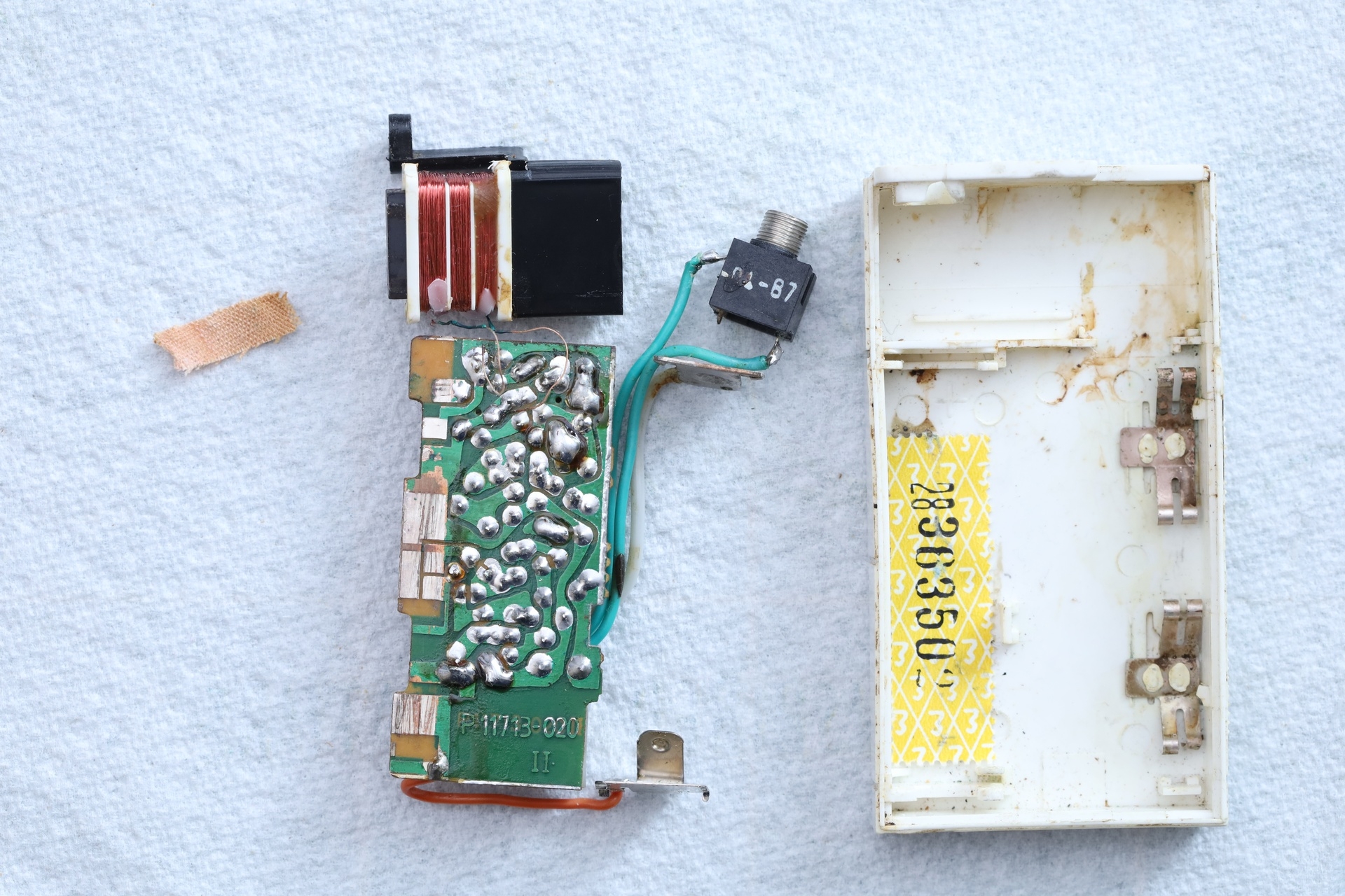
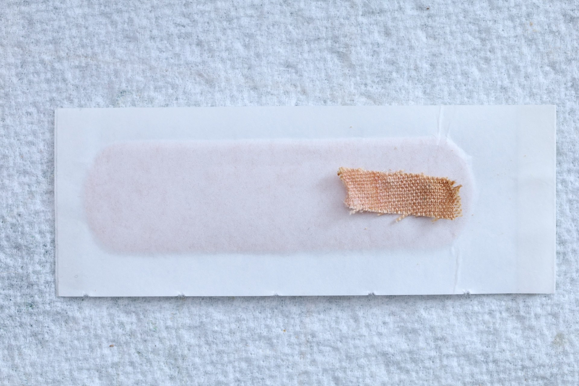
One of the last steps was to use replace the band-aid used as additional isolation for the antenna leads not to rub / touch the circuit board. Unfortunately, the original one lost all its stickiness, so some aftermarket replica was required. I could have used some Kapton tape but, why not 🙂
Some observations / reflections
JFET operating region – Simulation
The JFET (BF245A) is connected as common drain / source follower but I was curious if it runs in the ohmic region or in the active region. A JFET transistor works in ohmic region if:
$$V_{DS} < V_{GS} – V_P$$
\(V_D\) is almost battery voltage, let’s say 1.4V. \(V_S\) is 1V indicated in schematic. Thus \(V_{DS} = 0.4V\). In the LTspice simulation, \(V_{DS}\) is approx 0.57V.
\(V_{GS} = -1V\) (the voltage on the gate is almost nothing coming from the antenna, compared to \(V_S\) which is 1V).
\(V_P\) for BF245A is -1.73V (according to the LTspice model I found).
Let’s check: 0.5 < -1V – (-1.73V) => 0.5 < -1 + 1.73 => 0.5 < 0.73 which is true => so, in the simulation, the J-FET runs in the ohmic region.
JFET operating region – Realistic
The \(V_S\) in this radio is 0.492V (instead of the 1V mentioned in the schematic). This means that \(V_{GS}\) is ~ -0.5V (as voltage on the gate is almost 0, it is the voltage from the LT tank circuit). \(V_{DS}\) is about 0.888V.
Redoing the calculations: \(V_{GS} – V_P\) = -0.492V + 1.73 = 1.238V, which is larger than the \(V_{DS} = 0.888V\) => JFET is still in ohmic region.
It is interesting that the Radio Ric (the previous model) had the JFET operating in common-source mode (output taken from D terminal), thus, the ohmic-region setup is an upgrade.
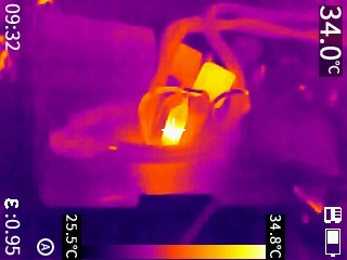
Heat
The headphones have 8Ω DC resistance. I do observe a bit of heat coming out of R17 (and associated T6 transistor):
I do have few more headphones (not original) but they are all 8Ω. It would have been interesting to test with a 200Ω ones.
LTspice – Tuning Selectivity
The RF frontend seem easy enough to try to have it in LTspice, and I have to admit, I spent way too much time trying various ways to simulate the RF input coming from the antenna. After a while, I got the idea of trying a 3D plot of the selectivity of the radio. LTspice does offer have a flat view and makes it easy to do a parameter sweep (such as the L value of the antenna, simulating a “band scan”), but what about in 3D ?
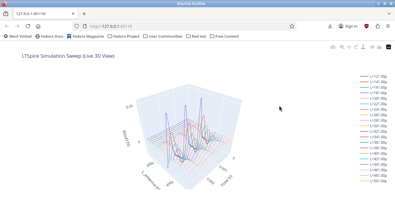
For the simulation I used a Fedora VM, with LTspice running in Wine and simulation controlled externally via PyLTSpice library. Only L value was varied, to simulate the scanning. I left the equivalent series resistor constant (12.67Ω, measured with NanoVNA at 1151MHz, without the ferrite bar), since it doesn’t change that much inside the AM band frequency range.
Results show that if two radio stations are nearby, you will hear them both. Selectivity is very poor but is understandable for a “toy” radio. Back in the day, there weren’t many AM stations in Romania, so it wasn’t a problem.
Battery Holder
I have also spotted that the bit of plastic holding down the battery negative connector is missing:
With the connector in the intended position, the AA battery is a very tight fit. Thus, I moved it into the slot behind.
Conclusions
This radio had a bad life, cracked plastics and lots of corrosion. Feels good to have it fixed, especially since it brings back a lot of nostalgia for me. I will keep the original parts I took out, and will be on the lookout for smaller 56pF capacitors.

It is also difficult to record a video of it, because I’d like to bring the headphones close to the microphone of the phone, but then, it becomes an antenna carrying and there’s a lot of hiss.
References
http://www.regiradio.nhely.hu/roman/rortr/ric2.html – Schematics
https://pypi.org/project/PyLTSpice – Python library for controlling LTspice.
https://miciielectronisti.ro/2019/03/radio-ric-scurta-istorie-si-restaurare/ – Nice history of the Radio Ric radios.
https://www.elforum.info/topic/119516-ric – Discussions and insights on the Ric radios.
Mike
Thanks a lot for this article and all those HD pictures.
I had this radio like 30 years back.
At that time I knew nothing about electronics.
Just kept disassembling and reassembling it.
You brought me tons of memories I thought I would never have. Thank you.